Does arc voltage depend on welding current?
» Articles » Does arc voltage depend on welding current
Page 1
The arc voltage increases with increasing arc length, while the width of the weld becomes larger and the penetration depth decreases slightly. [2]
| Form of static (volt-ampere arc characteristic [3] |
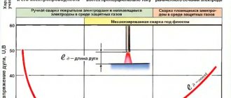
The arc voltage depends on the welding current and arc length. This dependence is called the static (volt-ampere) characteristic of the arc. In Fig. Figure 24 shows approximate shapes of the static characteristics of arcs 2 and 3 mm long.
As can be seen from the curves, the arc voltage drops sharply at low current values. For high currents, which are usually used in automatic welding, the arc voltage does not depend on the current, but is determined only by the arc length.
[4]
The arc voltage varies proportionally to the length of the arc. As the length of the arc increases, its voltage increases and the proportion of heat used to melt the flux and metal increases. As a result, the width of the seam increases, and the penetration depth and reinforcement height decrease.
[5]
The arc voltage depends on its length: the longer the arc, the higher the voltage in it. As the arc voltage increases, the weld width increases and the penetration depth decreases.
The arc voltage is automatically set depending on the selected welding current value for a given arc length. [6]
| Characteristics of welding tractors. [7] |
The arc voltage activates the coil of the voltage relay RNZ-1.
The voltage relay is triggered: three normally open contacts turn on the three-phase motor M for moving the tractor, and a normally closed contact will open the brushes of the motor UM - 22, the armature of which will receive normal power from the potentiometer R - Rz and change the direction of its rotation. From this moment, the steady process of operation of the welding circuit begins: the tractor moves along the workpiece being welded, and the electrode wire is fed into the burning zone of the welding arc. [8]
The arc voltage in a steady state does not depend on the current strength, but depends only on the length of the arc, which during welding with a consumable electrode can change many times, which is largely associated with the processes of melting and metal transfer (see Chapter [10]
| The process of disconnecting a short-circuited DC circuit. [eleven] |
The arc voltage increases linearly to a maximum value and then remains unchanged until the arc goes out. [12]
The arc voltage is limited by the electrical strength of the equipment. When the machine is triggered, the voltage on the rotor rings s / U - ia should not exceed half the amplitude of the rotor test voltage. [14]
Arc voltage is a very important element of the welding process. [15]
Pages: 1 2 3 4 5
www.ngpedia.ru
Electric arc during welding - stable but variable
Welded structures can be found today in a variety of areas of production. For example, it is impossible to find a single building in the creation of which welded structures would not be used.
That is why increased demands are placed on production technologies for a wide variety of welded structures.
And at the same time, each design, depending on its characteristics, requires a separate integrated approach.
In this article, the author tried to give a fairly detailed answer to the questions: “what is the current of a welding arc, and what types of current are there?” In simple words, what is usually written in textbooks about the current of the welding arc. The arc of direct and alternating currents is considered.
In this article, we will get acquainted with the standardization of welding work, the organization of the workplace and labor, which greatly influence labor productivity, and we will look at the basic formulas that will help calculate work standards.
stalevarim.ru
Influence of arc voltage on weld shape
The concept of submerged arc welding mode includes current strength, arc voltage and welding speed. Technological factors such as the diameter of the electrode wire and the wire feed speed are set based on the conditions for obtaining the required current strength.
The current strength has a significant effect on the penetration depth and a minor effect on the width of the seam. As the current increases, the depth of penetration increases almost proportionally. According to B.I. Medovar, an increase in current strength by 100 A leads to an increase in the penetration depth by an average of 1 mm in the case of welding butt seams without groove.
The depth of penetration is also influenced by the type of current. Thus, when welding with direct current, the depth of penetration with reverse polarity is greater than with direct polarity.
Fig. 72. The influence of arc voltage on the shape of the seam
The magnitude of the current is affected by the diameter of the electrode and its feed rate.
In turn, the diameter of the electrode affects the penetration depth. Thus, at the same current strength, the depth of penetration increases with decreasing diameter of the electrode wire. The latter is associated with an increase in current density.
The arc voltage has a significant effect on the width of the weld and only a minor effect on the penetration depth. As the voltage increases, the weld width increases significantly with a slight decrease in the penetration depth. The effect of stress on weld dimensions is shown in Fig. 72.
As in the case of manual arc welding, metal of small thickness is more sensitive to welding modes. In this regard, when welding such metal, direct current should be used, which gives a more constant arc voltage compared to alternating current.
For good formation of a seam when welding under a layer of flux, it is necessary to maintain a certain ratio between voltage and current. Similar ratios are given in table. 60.
www.prosvarky.ru
Welding properties of the arc and the processes occurring in it
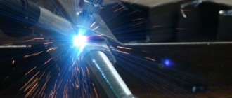
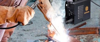
The welding arc is the main element of electric arc welding. It is the welding arc that is the main “supplier” of thermal energy, due to which the welding electrode and metal melt, followed by the formation of a weld. The strength and continuity of the welded joint depends on how stable the arc is.
Manual arc welding takes first place as a method of connecting metal structures. The article will tell you how the arc welding technique depends on other factors, and how to move the electrode correctly to get a high-quality weld.
The article provides a detailed analysis of the characteristics of the welding arc and their features in various types of welding. We talk about the current-voltage characteristic, arc elasticity and efficiency indicators. It is indicated why it is important to monitor these characteristics during the welding process.
Practice welding deception. How not to make a mistake when choosing a device. Part 2
This feature of the device, in the conditions of domestic power grids, is certainly important. If the inverter cannot cope with a network drawdown of up to 190V, it is worthless.
Working in a garage or in a country house, in places where networks cannot boast of stability, will simply be impossible.
Even if your outlet has a stable 220V, then when using extension cords of 30, 50 or 100 meters, drawdowns still cannot be avoided.
Deception, as in the case of additional functions, is caused by manufacturers' fear of losing in the competition. If all equipment sellers promise that their inverters operate at 160 V at the outlet, why not say that our “Oak” cannot operate at 120 V without losing quality in the seam.
The simplest way to check the performance of an inverter at reduced voltage is to use a device called LATR.
Laboratory AutoTransformer allows you to set the required voltage parameters and see how the welding machine connected through the device will cope with welding. As you understand, this equipment is not found in every garage.
The Aurora laboratory has this device, and we will definitely conduct tests for operation at low voltage in the network. So stay tuned for more video updates on the Aurora Online Channel.
The other extreme is the promise of welding equipment sellers that at 100-110V in the supply network, the device will produce the same welding result as at the rated voltage. This is definitely not true.
The welding current of the machine decreases in proportion to the network voltage. The only question is at what voltage in the socket the quality of the seam when working with a given electrode diameter will become unacceptable.
For some devices this is 180 V, for others 160 V.
Let us repeat once again, working with a supply voltage of 220 V is a guarantee of ideal fusion of the edges of the metal being welded; a decrease in voltage is an emergency situation and one cannot expect high quality welding seams under such conditions.
Judging by the advertisement, welding at ultra-low voltage in the supply network is almost the main requirement for the device. Meanwhile, we would like to draw the attention of buyers that welding is a multi-component process.
In addition to the actual fusion of the metal edges, a significant amount of preparatory work needs to be carried out. Cut the workpieces, clean the welding area, and finally illuminate the welder’s workplace.
And if the voltage drops to 140-160V, neither the angle grinder nor even the lighting will work.
Welding current control limits
This characteristic allows you to understand how the welding machine will cope with work with different electrode diameters. The thinner the metal being welded, the lower the welding current should be, and, accordingly, the diameter of the selected electrode.
Considering that the minimum diameter of electrodes on sale is 1.6 mm, the current for them should be in the region of 40-50A. To work with large thicknesses of workpieces, the current, on the contrary, must be high, for a 4mm electrode, 140-200A.
Exam tickets to test the knowledge of welding specialists level 1
TICKET 2
QUESTION 1. What position of the electrode during welding leads to an increase in the penetration depth during RDS?
1. Welding at an angle forward.
2. Backward angle welding.
3. Welding with a vertical electrode.
QUESTION 2. Does the arc voltage depend on the welding current when using power sources with a falling characteristic?
3. Depends on low and high values of welding current.
QUESTION 3. What class of steels do welding wires Sv-12Kh11NMF, Sv-10Kh17T, Sv-06Kh19N9T belong to?
QUESTION 4. Which of the listed factors most influences the width of the seam in RDS?
1. Transverse vibrations of the electrode.
2. Arc voltage.
3. The magnitude of the welding current.
QUESTION 5. For what purpose is one of the ends of the electrode uncoated?
1. To ensure the supply of current to the electrode.
2. In order to save coverage.
3. To determine the brand of electrode.
QUESTION 6. What should be the type and polarity of the current when welding joints made of carbon steels with electrodes with a basic coating?
1. Alternating current.
2. Direct current of reverse polarity.
3. Direct current of straight polarity.
QUESTION 7. What are the requirements for the storage room for welding materials?
1. Welding materials are stored in a specially equipped room without restrictions on temperature and air humidity.
2. Welding materials are stored in a specially equipped room at positive air temperatures.
3. Welding materials are stored in a specially equipped room at a temperature not lower than 15 0C and a relative air humidity of not more than 50%.
QUESTION 8. For welding which group of steels are electrodes of types E50, E50A, E42A, E55 used?
1. For welding structural steels of increased and high strength.
2. For welding carbon steels.
3. For welding high-alloy steels.
QUESTION 9. Why does a welder need special clothing?
1. To protect the welder from harmful aerosols released.
2. To protect the welder from electric shock.
3. To protect the welder from thermal, light, mechanical and other influences of the welding process.
QUESTION 10. How does the strength of the welding current change with increasing arc length during manual arc welding with stick electrodes?
1. Increasing the arc length leads to a decrease in current strength.
2. An increase in arc length leads to an increase in welding current.
3. The welding current remains unchanged.
QUESTION 11. What regulates the electrode calcination mode?
1. Production experience of the welder.
2. Technical passport for welding materials.
3. Recommendations of supervisory authorities.
QUESTION 12. For what purpose are electrodes calcined?
1. To remove sulfur and phosphorus.
2. To increase the strength of the electrode coating.
3. To remove moisture from the electrode coating.
QUESTION 13. What steels are classified as carbon steels?
1. Steel St3sp5, Steel 10, Steel 15, Steel 20L, Steel 20K, Steel 22K.
3. 08Х14МФ, 1Х12В2МФ, 25Х30Н.
QUESTION 14. What does the letter and the number following it mean in the marking of steels and alloys?
1. Manufacturer's marks.
2. Designation of heat number and batch of metal.
3. Symbol of the alloying element in steel and its content in percentage.
QUESTION 15. Which steels belong to the group of satisfactorily weldable steels?
1. With a carbon content of 0.25-0.35%.
2. With sulfur and phosphorus content up to 0.05%.
3. With silicon and manganese content up to 0.5%.
QUESTION 16. Which of the following technology violations can lead to porosity of seams?
1. Poor cleaning of edges before welding to remove rust and traces of grease.
2. High current when welding.
3. Small gap at the joint.
QUESTION 17. What determines the magnitude of the deformation of the metal being welded to a greater extent?
1. From the tendency of steel to harden.
2. From uneven heating.
3. From the brand of electrode used for welding.
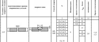
QUESTION 18. Indicate the size of the gap between the welded edges of sheet elements up to 5 mm thick in accordance with GOST 5264-80?
QUESTION 19. What color is recommended to paint the walls and equipment of welding shops?
1. Red, orange.
3. Gray (steel) color with a matte tint.
QUESTION 20. Specify the symbols of welded joints?
1. C - butt, U - corner, T - T, N - lap; the letter and number following it are the symbol of the welded joint.
2. C - butt welding, U - corner welding, H - lap welding, T - spot welding; The numbers after the letters indicate the method and method of welding.
3. S - butt, U - corner, T - T, P - ceiling seam; The numbers after the letters indicate the methods and scope of control.
To move to the next page, use the page navigation below.
Selecting welding mode: current, arc length, polarity
Selecting welding mode: current, arc length, polarity
To get a high-quality and reliable welding seam, you need to understand which electrodes are best to use and which mode of manual arc welding to choose. In addition, it is important to take into account other equally significant factors, such as: the composition and thickness of the metal, the dimensions of the workpiece being welded, and for what purposes it will be used in the future.
In general, the welding mode is selected according to many factors and after analyzing the data obtained. In this article from the website mmasvarka.ru we will consider the main factors that, to one degree or another, can influence the choice of mode.
Welding mode selection
So, what factors influence the choice of one or another mode of manual arc welding. First of all, this is:
The main criteria when choosing a mode for MMA welding, of course, is determined by the burning nature of the welding arc, the stability of which depends on how correctly the current strength is selected for some specific electrodes. The higher the current, the larger the diameter of the electrodes you can weld thick metal. In simple words, high currents ensure better arc burning and good heating of the metal.
You should know that when a seam is applied vertically, the current strength changes less than when applied horizontally, by about 15%.
For ceiling seams, the value of the welding current will be even less, by about 20%. Very often, values regarding the current strength are on the packaging with electrodes.
In addition, you can determine what current strength to set on the welding machine from the table below with the values.
Average welding current (A):
- Electrode diameter (1.6 mm) - electrode with rutile and basic coating (30-55 A) and (50-75 A);
- Electrode diameter (2 mm) - electrode with rutile and basic coating (40-70 A) and (60-100 A);
- Electrode diameter (2.5 mm) - electrode with rutile and basic coating (50-100 A) and (70-120 A);
- Electrode diameter (3 mm) - electrode with rutile and basic coating (80-130 A) and (110-150 A);
- Electrode diameter (4 mm) - electrode with rutile and basic coating (120-170 A) and (140-200 A);
In turn, in order to correctly determine the diameter of the electrode, it is necessary to take into account the thickness of the metal, the welding method and the geometric location of the seam. So, for example, for each electrode its own “own” current value is selected. If you greatly increase its performance, you can easily burn through the metal or, conversely, not achieve a high-quality and reliable weld.
Selecting current depending on the diameter of the electrodes
Thin metal, no more than 1 mm thick, is welded with 1 mm electrodes, and the current strength is set to the minimum possible values, in the range of 10-30 A. When welding thicker metal, up to 2 mm, electrodes of a slightly larger diameter are used, 1. 5 or 2 mm. The current strength for welding with these electrodes is set in the range of 30-50 A.
A 3 mm electrode is used to weld metal up to 4 mm, and the current on the inverter is set to 60-120 A. For welding metals over 10 mm thick, much thicker electrodes are already used - 4 and 5 mm. For their normal use, the welding machine must be set to a current of more than 120 A.
Welding arc length
To achieve a good connection, it is important to correctly determine not only the diameter of the welding electrodes, but also the length of the welding arc. There is a common belief among welders that the length of the arc should correspond to the diameter of the electrode used. However, it is very difficult for novice electric welders to maintain such a short arc without it being pulled to the side.
Therefore, when selecting this value, you should proceed from the current strength and diameter of the electrodes used for welding:
- For electrodes up to 2 mm - the arc length is 2-2.5 mm;
- For 3 mm electrodes, the arc length is 3.5 mm;
- For 4 mm electrodes, the arc length is 4.5 mm;
- For 5 mm electrodes, the arc length is maintained within 5.5 mm.
In addition, it is important to take into account the optimal welding speed, which also largely depends on the current strength and other features. Here you can follow one proven path, and with the correct selection of welding speed, the welding seam should be approximately twice the diameter of the electrode used.
Reverse or straight polarity?
To select the welding mode with a coated stick electrode, it is equally important to determine which operating mode to switch the welding inverter to. There are two of them, reverse and direct polarity.
In order to weld thin metal with an inverter and not burn it later, it is recommended to switch the welding machine to reverse polarity, when the flow of electrodes is directed not at the workpiece, but at the electrode. Conversely, if you connect the inverter in direct polarity, you can improve the quality of welding, for example, when you need to weld thick metal.
To connect the inverter in reverse polarity (for welding thin metal):
- A positive terminal is connected to the holder with the electrode, and a negative terminal is connected to the workpiece.
To connect the inverter in direct polarity (for welding thick metals):
- A negative terminal is connected to the holder with the electrode, and a positive terminal is connected to the workpiece.
To choose the right welding mode with an inverter, you need to take into account many different nuances. Only in this way will it be possible to achieve a high-quality and reliable welding joint that will withstand heavy loads.
WELDING SPEED FOR MANUAL ELECTRIC ARC WELDING
Manual electric arc welding is characterized by the speed of its implementation. It affects the width of the seam. The faster the speed, the narrower the seam. When working slowly, the seam is wide. Transverse movements of the electrode during the joining process also affect the width and also the depth of the seam. Do not cook too quickly or too slowly. When working very quickly, spaces unfilled with metal will form, which can cause cracks. Working the electrode very slowly allows the molten metal to spread, which will make the product of poor quality. The movements of the electrode end can also be different (zigzags, herringbones).
Thus, choosing a manual arc welding mode is a set of actions aimed at finding the necessary parameters for connecting a specific product. If you are not a professional or even a complete beginner in this matter, then choosing the welding mode required for a particular product may not work the first time. But this is why there is practice, reference information, and instructions for reference, which indicate the parameters of manual arc welding depending on various indicators. It is worth noting that in each case all parameters are selected individually. You can select manual arc welding modes with coated electrodes yourself.
Does arc voltage depend on welding current? — Metals, equipment, instructions
The conditions for ignition and burning of the arc depend on the type of current, polarity, chemical composition of the electrodes, gas gap and its length.
Ignition and burning of the arc proceed better with direct current.
The no-load voltage supplied to the electrodes, taking into account labor safety during welding, does not exceed 80 V on alternating current and 90 V on direct current. Typically, the arc ignition voltage is 1.2-2.5 times greater than the arc voltage on alternating current, and 1.2-1.4 times greater on direct current.
To ignite an arc, a higher voltage is required than for burning an arc.
First condition
The arc is ignited by heating the end of the electrode (cathode).
When the electrode comes into contact with the workpiece, a closed welding circuit is created, the end of the cathode electrode heats up due to the release of heat when current passes through a contact that has high electrical resistance, and when the electrode is separated from the workpiece at a distance of 1 mm (or slightly more), the arc is ignited.
At the moment the electrode is separated from the product, thermionic emission begins from the cathode heated by the short circuit. The electron current ionizes the gases and metal vapors located in the interelectrode gap, and from this moment electron and ion currents appear in the arc.
Maintaining continuous arc burning will be carried out if the energy influx into the arc exceeds losses in it due to radiation, convection, dissociation, electromagnetic losses, etc.
In the event of short circuits by drops of electrode material formed at the end of the melting electrode and transferred to the workpiece, re-ignition of the arc occurs spontaneously if the cathode temperature remains high enough. This temperature depends on the composition of the cathode material, the current density in it, etc.
Thus, the first condition for ignition and burning of the arc is the presence of a special electrical power source for the arc, which allows the cathode to be quickly heated to the required temperature.
Second condition
The second condition for the ignition and burning of an arc is the presence of ionization in the arc column. A consumable arc is essentially an arc in metal vapor rather than gas.
This occurs because the ionization potential of metal vapors is significantly lower than that of gases; for example, the ionization potentials of the gases He, F, Ar, H2, N2, CO2, O2 are respectively 24.5 - 12.5, and for the metals Fe, Al, Na, K - 7.83-4.32 eV.
The burning arc can be stretched to a certain length, after which it goes out. The higher the degree of ionization, the longer the arc will be.
The length of the arc burning without breaking characterizes the stability of the arc.
Arc stability
The stability of the arc depends on a number of its characteristics, for example, on the temperature of the cathode, its thermionic ability, the degree of ionization of the atmosphere, etc.
The stability of the arc increases with the increase in its atmosphere of elements with low ionization potential, such as potassium, sodium, etc.
Stable arcs are installed in gases with relatively low thermal conductivity (argon, krypton), and in gases with relatively high thermal conductivity (helium, hydrogen, nitrogen), increased arc voltage is required for stable combustion. In the latter case, welding is performed with a shorter arc using a non-consumable electrode.
Third condition
The third condition for welding with alternating current is the presence of reactance (increased inductance) in the welding circuit, which increases the stability of the arc. In an AC welding circuit that has only ohmic resistance, breaks occur when the arc burns (100 breaks per second at an alternating current frequency of 50 Hz).
When the reactance is included in the AC welding circuit, there are no breaks in the arc.
Electrical inductance is included not only in the AC welding circuit, but even in the DC circuit.
Currently, some welding rectifiers are manufactured with an inductance included in the welding circuit in order to improve arc stability and welding quality.
This is especially necessary if semi-automatic hose welding is carried out in CO; The larger the diameter of the welding wire and the current, the greater the inductance value should be in the welding circuit.
Fourth condition
The fourth condition for ignition and burning of an arc at any type of current depends on the characteristics of the arc power source: the power source must support the arc in the presence of disturbances in the form of changes in the voltage in the network, the surface topography of the product being welded, the feed speed of the welding wire, etc.
What influences the choice of welding current
When performing welding work, the quality of the resulting connection depends primarily on how correctly the welding mode is selected. The main adjustable parameter of the process or the main operating characteristic is the electric current, which is called welding current.
The current strength during welding depends mainly on the parameters of the workpiece to be welded and on some other factors.
Basic Concepts
Welding current, in addition to its absolute value expressed in amperes, is characterized by constancy or periodic changes in magnitude and direction over time.
In the first case, the current is called constant. Its sources are welding rectifiers, autonomous welding generators, as well as modern welding machines using inverter technology.
If the direction and (or) magnitude of the current changes over time, then it is called alternating. The sources of alternating welding current are step-down transformers, the primary winding of which is connected to an alternating current network of 220 or 380 volts.
The choice of welding parameters, that is, its mode, is influenced by the following factors, which are closely related to each other:
- thickness of the workpiece being welded;
- type of metal or alloy to be welded;
- diameter of the electrode used;
- location and nature of the seam.
The selected current operating mode of the welding machine determines the amount of energy of the electric arc. The higher the value of this parameter, the more heat is released when the arc burns, which means that the workpiece and the electrode used melt more intensely and deeply.
From here it becomes clear that the thicker and more massive the metal being welded, the higher the current value should be set when welding it . In addition, there is a direct relationship between the thickness of the workpiece, the current mode and the diameter of the electrode during manual arc welding.
Dependence on electrode thickness
Regulatory literature on welding contains many tables that allow you to select the required electrode diameter and welding current value for welding workpieces of a certain thickness.
As the welding current increases, the melting rate of both the workpiece and the electrode material increases, this determines the direct relationship between the welding current and the diameter of the electrode.
For example, if with an electrode having a diameter of 2 mm, it is recommended to weld metal with a thickness of 2 - 3 mm, while choosing a welding current in the range of 40 - 80 amperes, then for electrodes with a diameter of 5 - 6 mm, a current value of 220 - 320 amperes is indicated when welding metal 10 - 24 mm.
It is worth mentioning one more characteristic of the welding process related to the diameter of the electrode used. We are talking about the welding current density, determined by the ratio of the welding current to the cross-sectional area of the electric arc and measured in amperes per square millimeter (A/mm2).
This parameter plays an important role in the formation of the weld. As the diameter of the electrode increases, the density decreases at constant current settings of the device.
This is due to the fact that an electrode with a larger diameter creates a thicker arc with a larger area. The density indicator also depends on the length of the electric arc.
As the discharge gap between the electrode and the workpiece increases, the arc extends, becoming thinner, reducing the cross-sectional area of the discharge. At the same time, the temperature created by the arc decreases, and the process of transfer of matter by the electric discharge slows down.
With a further increase in the gap, the process begins to lose stability, the surface of the weld pool becomes uneven, and eventually the arc discharge goes out. Thus, within relatively small limits, the energy of the welding process can be adjusted by changing the arc length.
As for semi-automatic welding, the role of the electrode here is played by a special welding wire, the diameter of which is also selected according to the tables, depending on the characteristics of the metal being welded and its thickness.
Practical definition
It will not be difficult for an experienced welder to choose the right welding mode if the dimensions of the workpieces and the characteristics of the metal from which they are made are known. If necessary, you can refer to one of the technological tables.
It is necessary to pay attention to the recommendations attached to the electrodes themselves and the welding machine in the instructions. There are also empirical formulas that can be used to calculate the welding current.
For electrodes having a diameter less than 4 mm or more than 6 mm, the following formula is sometimes used:
I = (20 + 6d) d
In this formula, I is the welding current, expressed in Amperes, d is the diameter of the electrode in millimeters.
To select the welding current when using electrodes with a diameter of less than 3 mm and working in the simplest lower position, you can apply the following ratio:
Does arc voltage depend on welding current - Machine tools, welding, metalworking
A welding arc is an electric arc discharge in an ionized mixture of gases, metal vapors and components that make up electrode coatings, fluxes and other means.
Physical and electrical properties of the welding arc
For an electrical discharge to occur, the gas gap between the electrodes must be ionized. The ionization process proceeds in the following order. When the end of the electrode and the workpiece come into contact, the protrusions of the rough surfaces are instantly heated by current to the melting and evaporation temperature due to the high ohmic resistance of the contact.
After the electrode is separated from the product, the heated end of the electrode (negative pole) begins to emit electrons, rushing to the anode under the influence of the potential difference between the electrodes.
When colliding with electrode metal particles, which are present in the form of vapors in the interelectrode gap, electrons ionize them.
Ionization instantly covers the entire interelectrode gap, and it becomes electrically conductive.
During the arcing process, ionization is maintained due to high temperature.
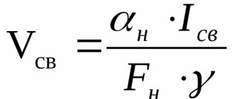
The arc voltage is equal to the sum of the voltage drops in its three main (Fig. 1) areas:
Uд=Uк+ Uc+ Ua =f(Iд),
where Ud is the arc voltage, V; UK is the voltage drop at the cathode, V; Uc is the voltage drop in the arc column, V; Ua is the voltage drop across the anode, V; Id is the current strength in the arc.
Fig.1. Arc voltage drop distribution
The dependence of the arc voltage on the strength of the welding current is called the static (volt-ampere) characteristic of the arc.
In general, the static characteristics of the arc are shown in Fig. 2. At low current values in the electrode (region 1), the static characteristic of the arc decreases.
At average current values (for manual and automatic submerged arc welding), the arc voltage does not depend on the current strength (region 2, hard characteristic).
In this case, with sufficient accuracy, the static characteristic can be expressed by the equation
Ud= a+ bld,
where ld is the length of the arc, mm; a, b are constant coefficients depending on the material of the electrodes, pressure and properties of the gaseous medium.
Fig.2. General view of the static characteristics of the arc
From this equation it follows that the voltage on the arc, all other things being equal, will depend on the length of the arc column.
An increasing static characteristic of the arc (region 3, see Fig. 2) is obtained at high current strength (with automatic submerged arc welding or when welding in a shielding gas environment).
AC welding arc
Due to the fact that the instantaneous values of the alternating current pass through zero 100 times per second, and the cathode spot, which is the source of electron emission, also changes its location, the ionization of the arc gap turns out to be less stable and the welding arc is less stable, other things being equal, compared to the arc direct current.
If the arc is connected to an alternating current circuit in series with an active resistance, then the instantaneous values of the source voltage and welding current are in phase. During each half-cycle, the arc dies out and is re-ignited (restored) after a certain period of time until the voltage of the current source rises to a certain value, called the re-ignition voltage.
Ignition of the arc is characterized by the beginning of the passage of current in the welding circuit. In each half-cycle there is a break in the passage of current when the arc fades. These breaks are called arc extinction times.
The moment of extinction occurs at a slightly lower instantaneous value of the source voltage than at the moment of ignition, for which higher values are required to obtain ionization of the cooled gap.
The arc extinction time depends on the maximum arc ignition voltage and the frequency of the alternating current.
The arc recovery time decreases with increasing open circuit voltage and when using higher frequencies. This time also decreases when the ignition voltage is reduced. Of these measures to increase the stability of the arc, the most common is to reduce the ignition voltage, which is achieved by using electrodes with ionizing coatings.
The magnitude of the ignition voltage depends on a number of factors, primarily on the magnitude of the arc current. As the welding current increases, the arc ignition voltage decreases.
For open arc welding, the ignition voltage Uz and arc voltage Ud have the following relationship:
Uз = (1.3 – 2.5) Uд
When welding at high currents under submerged arc, the ignition voltage is almost equal to the arc voltage.
Increasing the open circuit voltage of the power supply is limited by safety regulations, and the use of high frequencies requires the use of special equipment.
A generally accepted measure to increase the stability of an alternating current welding arc is to include coils with a steel core (chokes) in the welding circuit, which allow welding to be carried out with metal electrodes at a welding transformer voltage of the order of 60 - 65V and a standard frequency. In this case, the coating of the electrodes must contain a sufficient amount of ionizing components.
What is a welding arc, its definition
A welding arc is considered to be a very large electrical discharge in terms of power and duration that exists between the electrodes to which voltage is applied in a mixture of gases.
Its properties are characterized by high temperature and current density, thanks to which it is capable of melting metals with a melting point above 3000 degrees.
In general, we can say that an electric arc is a conductor made of gas that converts electrical energy into thermal energy. Electric charge is the passage of electric current through a gaseous medium.
There are several types of electrical discharge:
- Glow discharge. Occurs at low pressure, used in fluorescent lamps and plasma screens;
- Spark discharge. Occurs when the pressure is equal to atmospheric pressure and has an intermittent shape. Lightning corresponds to a spark discharge; it is also used to ignite internal combustion engines;
- Arc discharge. Used for welding and lighting. It is characterized by a continuous form and occurs at atmospheric pressure;
- Crown. It occurs when the body of the electrode is rough and inhomogeneous, the second electrode may be missing, that is, a jet appears. Used to purify gases from dust;
Nature and structure
The nature of the welding arc is not as complicated as it might seem at first glance. The electric current, passing through the cathode, then penetrates the ionized gas, a discharge occurs with a bright glow and a very high temperature, so the temperature of the electric arc can reach 7000 - 10000 degrees.
After this, the current flows to the material being welded.
Since the temperature is so high, the arc emits ultraviolet and infrared radiation that is harmful to the human body, it can harm the eyes or cause light burns on the skin, so proper protection is necessary when carrying out the welding process.
The structure of the welding arc consists of three main areas: anodic, cathodic and arc column. During arc burning, active spots are formed on the cathode and anode - areas in which the temperature reaches the highest values, it is through these areas that all electric current passes, the anode and cathode areas represent larger voltage drops.
The most favorable length is approximately 4-6mm; this length ensures a constant and favorable temperature.
Varieties
Types of welding arc differ in the welding current supply circuit and the environment in which they occur; the most common options are:
- Direct action. With this method, the welding machine is located parallel to the metal structure being welded and the arc occurs at an angle of ninety degrees relative to the electrode and metal;
- Indirect welding arc. Occurs when two electrodes are used, which are located at an angle of 40-60 degrees to the surface of the part being welded, an arc occurs between the electrodes and welds the metal;
There is also a classification depending on the atmosphere in which they occur:
- Open type. An arc of this type burns in air and a gas phase is formed around it, containing vapors of the material being welded, electrodes and their coatings;
- Closed type. The combustion of such an arc occurs under a layer of flux; vapors of metal, electrode and flux enter the gas phase formed around the arc;
- Arc with gas supply. Compressed gases are supplied to the burning arc - helium, argon, carbon dioxide, hydrogen and other various mixtures of gases; they are supplied so that the metal being welded does not oxidize; their supply contributes to a reducing or neutral environment. The gas phase around the arc includes the supplied gas, metal and electrode vapors;
They are also distinguished by the duration of action - stationary (for long-term use) and pulsed (for one-time use), by the material of the electrode used - carbon, tungsten - non-consumable electrodes and metal - consumable. The most common consumable electrode is steel. Today, welding with a non-consumable electrode is most often used. Thus, the types of welding arcs are varied.
Classification by duration
There is a classification of welding arc discharges according to their duration. Some processes are carried out when the arc is in a mode such as pulsed. Such devices weld in short bursts. For a short period of time, while flashing occurs, the temperature of the welding arc manages to increase to such a value that is enough to produce local melting of the metal. Welding occurs very precisely and only in the place where the device touches the workpiece. However, the vast majority of welding equipment uses a long-lasting welding arc. During this process, the electrode continuously moves along those edges that need to be connected. There are areas called weld pools. In such areas, the arc temperature is significantly increased, and it follows the electrode. After the electrode passes the area, the weld pool leaves after it, which is why the area begins to cool quite quickly. When cooled, a process called crystallization occurs. As a result, a weld seam occurs.