Welding is one of the most commonly used methods of joining metals and alloys. Even masters sometimes make seam defects, not to mention beginners. When carrying out such work at home, visual inspection is sufficient. In production, various methods are used to control the quality of the weld, and one of the most advanced is radiographic testing.
Brief description of the method
Metal parts are connected using different types of welding, which can result in weld defects.
It's connected with:
- violation of work technology;
- foreign bodies entering the welding site;
- insufficient welder qualifications, etc.
All this leads to a deterioration in the quality of the seam and a decrease in its strength.
X-ray inspection (RT) of welded joints is a non-destructive method that allows you to identify hidden defects at an early stage and avoid accidents in the future.
This is a highly accurate method with which you can objectively assess both the nature and size of defects. The technique allows you to monitor the condition of welds on pipelines, tanks, various equipment and metal structures, etc.
The essence of the radiographic control method
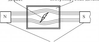
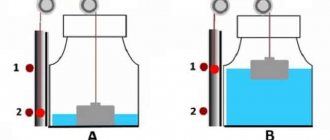
The principle of radiographic testing is based on examining a sample in a current of X-rays. On one side there is a radiation source, on the other there is a sensitive film or matrix. After passing through a homogeneous material, the same uniform illumination is obtained. If there are flaws and inhomogeneities in the sample, the illumination on the film or matrix changes.
The X-ray method of testing welded joints is one of the most reliable methods of non-destructive testing. It is used everywhere in cases where a high level of quality and reliability of a weld that meets the standards is required. Despite the slightly higher price of x-ray testing, its use is mandatory to confirm the suitability of critical products.
GOST and other requirements
The radiographic method of testing welded joints is regulated by GOST 7512-82. This method allows you to control the weld with a thickness of the welded elements from 1 to 400 mm, and when using powerful equipment - up to 500 mm.
For this purpose, X-ray, bremsstrahlung and gamma radiation are used, and radiographic film is used to obtain an image.
The basic requirements for accessories for such control are as follows:
- Markings comply with GOST 15843-79.
- Radiographic films meet technical specifications.
- The radiation source complies with GOST 20426-82.
- Intensifying screens can be metallic or fluorescent.
- Lightproof cassettes ensure that the screen is pressed tightly against the film.
- The lead screen protects the film from scattered radiation.
- Sensitivity standards can be plate, wire or groove.
X-ray television installations.
Using X-ray television installations developed at the Research Institute of Introscopy, it is possible to monitor welded joints with a sensitivity approaching that of the radiographic method, and with a productivity exceeding that of the latter [63].
The advantage of this method is the possibility of mechanizing the control process.
It is planned to equip the factories with X-ray television installations based on X-ray vidicons with a diameter of 18 and 90 mm - PTU-38 and PTU-39, installations with X-ray vidicons with a diameter of 150 mm, as well as installations such as RI-20T and RI-60TK, X-ray equipment with image brightness intensifiers.
An improvement in the method of x-ray inspection of industrial products is the recording of x-ray images using the xerographic method . It is used instead of photographic, and the cost of x-ray inspection is reduced while maintaining sensitivity to detecting defects, close to the radiographic method. The xerographic control method is more productive than the radiographic method.
To control welded joints in hard-to-reach places in the absence of power sources, when it is not possible to use X-ray units or accelerators, gamma flaw detection . In this case, gamma or bremsstrahlung radiation from radioactive isotopes is used to illuminate the welded joint. In the USSR, gamma rays were first used for flaw detection of metals in 1926 by workers at the State Radium Institute JI. V. Mysovsky and T. S. Izmailova.
They used natural radioactive preparations, radium mesothorium. However, the high cost of drugs did not allow the widespread introduction of gamma transillumination into production.
With the advent of artificial radioactive preparations - isotopes - in the early 50s, the artificial radioactive isotope of cobalt was widely used for industrial gammagraphy. The development of nuclear energy has made it possible to obtain isotopes with different radiation characteristics.
In the USSR, the following isotopes are most often used gamma flaw detection The radiation source required to solve production problems is selected depending on the thickness and density of the material and the possible control technology. For steel less than 15-20 mm thick, thulium-170 is used, for thicker samples other sources are used, while cobalt-60 is used for metal thicker than 40-60 mm.
Even before the beginning of the 50s, Soviet scientists and specialists carried out research work that contributed to the introduction of gamma flaw detection in factory conditions. The pioneer of the development and implementation of gamma flaw detection in a number of branches of mechanical engineering is S. T. Nazarov.
Fundamental research in the field of gamma flaw detection was carried out by S. V. Rumyantsev and his students [58, 59, 61].
The initiator of the widespread introduction of this method in industry in the post-war years was V. S. Sokolov. Specialists from the All-Russia Research Institute of Radiation Engineering made a great contribution to the development of methods and means of radioisotope flaw detection.
Properties and capabilities of X-ray
The peculiarity of radiography is that the permeability of materials depends on the length of the generated rays. In dense materials they are scattered and partially absorbed. The lower the density of the connection being tested, the clearer the image will be.
The ability of some chemical elements to glow for several seconds under the influence of X-ray radiation makes it possible to expose a special film and obtain an image of existing seam defects.
If the material being tested is homogeneous, the result will be a light and monochromatic image. If there are various defects, cavities, voids, it will have darkening.
Some models of flaw detectors use the ability of ionized air to transmit electricity. The higher the degree of ionization, the better the current is conducted. This principle makes it possible to obtain an image not on film, but on the screen of an oscilloscope when performing RC.
In large quantities, X-ray radiation negatively affects the human body, irradiating cells and tissues. Large doses lead to the development of radiation sickness and even death. Therefore, the use of fluoroscopy to control the quality of welds requires strict adherence to safety rules.
Physical methods for monitoring welds
Radiation flaw detection is an X-ray and gamma-graphic inspection method. X-ray and gamma-graphy is a method of obtaining on an X-ray film or screen an image of an object (product) illuminated by X-ray or gamma radiation. It is based on the ability of X-ray and gamma radiation to pass through opaque objects, including metals, and act on X-ray film and some chemical elements, due to which the latter fluoresce (glow).
In this case, defects that occur during welding in the body of the product and most often have the nature of voids (lack of penetration, cracks, cavities, pores, etc.), on X-ray film (on radiographs) have the form of spots (cavities, pores) or stripes (lack of penetration ).
Usually; 3 - 15% of the total length of the weld is visible. For particularly critical structures, all seams are visible.
X-ray devices used for product inspection consist of an X-ray tube, a power source and a control panel. A step-up transformer is used as a power source, the secondary circuit of which includes kenotrons to rectify the anode current and high-voltage capacitors, which allow doubling or tripling the voltage of the secondary winding of the transformer. The diagram of X-ray exposure of the product is shown in Fig. 120.
Depending on the transmission mode (with a metal thickness of up to 50 mm), the quality of the film and the correctness of its further processing, it is possible to identify defects measuring 1 - 3% of the thickness of the tested parts.
Currently, X-ray machines RUP-120-5-1, RUP-200-5, RUP-400-5, Mira-2D and Mira-3D, etc. are widely used.
Gamma radiation is produced as a result of the intra-atomic decay of radioactive substances. The following radioactive substances are used as sources of gamma radiation: thulium-170, iridium-192, cesium-13 7, cobalt-60 for translucent metal 1-60 mm thick.
Gamma radiation, acting on the film in the same way as x-rays, records welding defects on it. The sensitivity of gamma monitoring is lower than that of x-rays; for example, on gamma images, when steel 10-15 mm thick is transilluminated with cobalt-60, defects with a depth of 0.5 - 0.7 mm are revealed, while on x-ray images defects with a depth of 0.1-0.2 mm are visible.
The sensitivity of gamma images obtained using radioactive isotopes—thulium-170, iridium-192 and others—approaches the sensitivity of x-rays.
Gamma radiation is harmful to human health, so ampoules with radioactive substances are placed in special devices - gamma installations, which have a remote control (Fig. 121).
The diagram of panoramic scanning of welded joints of pipelines using a gamma source is shown in Fig. 122.
A weld seam during radiation flaw detection is rejected if the following defects are found on an x-ray or gamma image:
slag inclusions or cavities according to group A (individual defects) and B (cluster of defects) with a size along the seam height of more than 10% of the wall thickness, if it does not exceed 20 mm, and also more than 3 mm if the wall thickness is more than 20 mm;
slag inclusions located in a chain or a solid line along the seam (group B), with their total length exceeding 200 mm per 1 seam;
pores located in the form of a continuous mesh;
accumulation in certain areas of the seam of more than five pores per 1 cm2 of seam area.
Defects are divided into groups A, B, C according to the following criteria:
A - individual defects that, by their location, do not form a chain or cluster;
B - a chain of defects located on the same line in an amount of more than three with a distance between them equal to three times the size of the defects or less;
B - accumulation of defects in one place with an arrangement of more than three of them with a distance between them equal to three times the size of the defects or less.
Ultrasonic control method . This method is based on the ability of high-frequency vibrations with a frequency of about 20,000 Hz to penetrate the metal and be reflected from the surface of defects (from encountered obstacles). Reflected ultrasonic vibrations have the same speed as direct vibrations. This property is of primary importance in ultrasonic flaw detection.
Narrow directed beams of ultrasonic vibrations for flaw detection purposes are obtained using piezoelectric quartz or barium titanate plates (piezoelectric sensor). These crystals, placed in an electric field, give the reverse piezoelectric effect, that is, they convert electrical vibrations into mechanical ones. Thus, piezo crystals under the influence of high-frequency alternating current (0.8 - 2.5 MHz) become a source of ultrasonic vibrations and create a directed beam of ultrasonic waves into the controlled part.
The reflected ultrasonic vibrations are captured by the finder (probe) and then converted into electrical impulses. The reflected electrical vibrations are fed through an amplifier to an oscilloscope and cause the beam to deflect on the electron tube screen. The nature of the defect is judged by the type of deviation.
The diagram of the ultrasonic method for testing welded joints is shown in Fig. 123.
Modern ultrasonic flaw detectors operate according to a pulsed radiation scheme, i.e., ultrasonic vibrations from a piezocrystal are sent not continuously, but in pulses; during pauses, the reflected vibrations arrive at the same piezoelectric crystal, which ensures high purity of reception of the reflected waves.
The piezoelectric crystal of an ultrasonic flaw detector is placed in a special prismatic or flat probe. The surface on which the probe moves must be cleaned to a metallic shine. To ensure the necessary acoustic contact between the probe and the product being tested, a layer of mineral oil is applied.
The industry produces ultrasonic flaw detectors UDM-3, UD-55EM, DUK-13IM, etc. The sensitivity of flaw detectors ensures the detection of defects with an area of 2 mm2 or more. With the ultrasound method it is difficult to determine the nature of the defect. The most effective control is performed when the metal thickness is more than 15 mm; with a metal thickness of 4-15 mm, control by this method is possible, but it requires a very highly qualified flaw detector (operator).
Magnetic flaw detection method. The weld of a steel or cast iron product is coated with a mixture of oil and magnetic iron powder (particle size 5 - 10 microns). The product is magnetized by passing current through a winding consisting of several turns wound around the product. Under the influence of a magnetic field flowing around a defect, iron powder particles are located more densely around the defects
This method reveals surface defects up to 5-6 mm deep. The resolution of powder flaw detection is very low compared to other inspection methods, so it is effective mainly for inspecting smooth, clean, shiny surfaces. The magnetic method can be used to check the quality of parts made only from ferromagnetic metals.
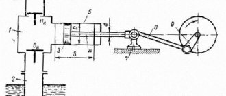
Magnetographic control method. With this method, developed in our country, the results are recorded on magnetic tape. The essence of this control method is to magnetize the welded joint and fix the magnetic flux on a ferromagnetic tape. The tape is applied to the controlled product, which is magnetized by a pulsed field. The magnetic field, in the presence of defects, is distributed over the surface of the part in different ways, and accordingly, the ferromagnetic particles on the tape will be magnetized to varying degrees. Then the ferromagnetic tape is removed from the controlled product and it is “pulled” through a reproducing device (Fig. 124), consisting of a pulling mechanism and an oscilloscope with an electrical pulse amplifier.
The results of magnetographic testing are viewed on screen 9 of oscilloscope 7, on which, in the presence of defects in the product under test, bursts (vertical pulses) appear. The size and nature of the defect in the welded joint is judged by the size and shape of the beam deflection on the oscilloscope screen.
The magnetographic method is used to control welded joints with a thickness of no more than 12 mm. This method can detect macrocracks, lack of penetration with a depth of 4 - 5% of the thickness of the tested metal, slag inclusions and gas pores.
The magnetographic method requires a highly qualified operator.
X-ray television control . The essence of the inspection method is that the weld defect is depicted at the moment of transmission on the television screen.
The diagram of the X-ray television installation is shown in Fig. 125. Welded joint 2 is scanned using an X-ray machine 1. X-ray radiation passes through an electron-optical converter 3, consisting of an evacuated tube, inside of which, on the side facing the radiation source (X-ray machine) and the product being scanned, a thin aluminum screen covered fluorescent layer. A photosensitive layer is applied to this layer - a photocathode (the same as in conventional television tubes). On the other hand, the electron-optical converter has a diaphragm and an intensifying screen. From such a converter, through transition optics 4, signals are sent to the transmitting television camera 5 and to the TV 7. This control method can dramatically increase the operator’s productivity. In this case, you can not only visually observe the internal state of the product being scanned, but also photograph it using a photo or film camera. This installation is controlled from control panel 6.
Connection density control . Welds are tested for tightness (tightness) with kerosene, compressed air (pneumatics), a vacuum apparatus, ammonia, helium and halide leak detectors and hydraulic pressure.
The kerosene test is used for vessels operating without internal pressure, and as a preliminary control method for vessels operating under pressure.
Kerosene has high capillarity. The technique for controlling the density of welds is based on this ability. Welded seams must be thoroughly cleaned of slag, dirt and inspected. Defects revealed by external inspection must be eliminated before inspection begins.
To identify defects (leaks) using the kerosene test method, one side of the welded joint is painted with chalk diluted in water. After the chalk has dried, the second side of the weld is generously moistened with kerosene. Kerosene, penetrating through defects in the weld, leaves greasy dark spots on the chalk paint, characterizing the presence and location of defects. Defects found are cut out and brewed again. Kerosene control is used at positive temperatures (above 0°C). Welds must be kept under kerosene of 12 g or more.
The vacuum method is used to check welds that cannot be tested with kerosene, air or water and which can only be accessed from one side, for example, welds on the bottoms of tanks, gas tanks and other containers.
The installation kit for monitoring the density of welded joints using the vacuum method includes the following equipment: a vacuum pump, a vacuum chamber with a vacuum meter and a pneumatic hose.
Hydraulic tests. With this control method, the welded product (vessel) is filled with water. Then a pump or hydraulic press creates a pressure that exceeds the working pressure by 1.25 times or more.
The hydraulic test method, holding time, pressure value and permissible leakage are established by the technical conditions for the controlled object. Hydraulic tests are performed to check the strength and density of steam and water boilers, pipelines and pressure vessels.
Compressed air test (pneumatic test). This test is used to test vessels and pipelines for leaks, usually only at the operating pressure of the product. The tightness of welded joints is checked with a soap solution or by immersing the vessel in water. Bubbles appear in places where gas passes through.
Scope of flaw detection
The X-ray method of checking welded joints makes it possible to accurately determine such parameters of existing defects as size, shape and location in space.
It allows you to control the quality of welds at critical facilities, such as main oil, gas, water pipelines, during the construction of structures and equipment for nuclear power plants, in machine, aircraft, shipbuilding, etc.
Advantages of radiographic control
The method of monitoring welded joints using x-ray scanning, despite its somewhat high cost, has a number of important advantages:
- Greater accuracy and information content;
- Ability to detect visible and invisible welding defects;
- Possibility of identifying internal defects and their localization;
- Quick results;
- Visibility of results;
- Objectivity of results and the possibility of their registration.
additional information
Before using the radiographic quality control method, you need to know that its diagnostic range is limited by the sensitivity of the device.
Using a flaw detector it is impossible to detect:
- voids that are 50% smaller than the standard values for the specified device and are located in a direction parallel to the action of the x-ray beam;
- inclusions located in the direction of the beam, the size of which is 2 times less than the sensitivity of the device;
- defects that coincide in the photograph with the edges and sharp corners of the elements being tested.
We recommend reading: What to do if your eyes hurt from welding
This method detects all other defects quickly, efficiently and with high accuracy.
Equipment design features
Nowadays, radiographic testing, related to digital flaw detection, is more often used. The resulting radiation image is converted into a digital image and the information is displayed on the screen.
The detector for monitoring x-rays or gamma radiation that passes through the object being tested is a photodiode with a scintillator, which is susceptible to radiation and emits a visible spectrum of light that is in direct proportion to quantum energy.
Such radiation produces a current inside the photodiode, the radiation is converted into electricity and then displayed on the screen.
The detector units are moved relative to the object being tested and receive a continuous stream of information, which is recorded in the computer memory for further detailed testing. To quickly assess the quality of the connection, the resulting image is immediately displayed on the screen.
Gamma ray flaw detectors
They provide a given frequency of gamma radiation intensity fluctuations. As a result of changes in radiation intensity, transverse stripes are created in the image.
The existing radiation intensity deviations are higher than the statistical noise values. Modern technology, equipped with advanced software, makes it possible to reduce these fluctuations. Such X-ray machines are conditionally applicable for performing RK welds.
X-ray device
These devices have a constant potential and high-frequency fluctuations, random in time. They provide a deviation in gamma radiation intensity of more than 1%. In this regard, the use of these devices when performing radiometric monitoring is not recommended.
For X-ray inspection it is necessary to use equipment that has the following indicators:
- radiation stability – more than 0.5%;
- fluctuation frequency – not higher than 0.1 Hz.
Operating principle of radiographic testing installations
The main part of the device used for radiographic monitoring of the condition of the seam is the emitter. It serves to create rays and emit them.
The emitter is made in the form of a vacuum vessel, which contains the anode, cathode and filament. During the acceleration that charged particles develop, X-rays are generated that illuminate the product under study.
The electrical potential created between the cathode and anode accelerates the electrons released by the cathode. These initial rays are still not enough for the device to operate.
When colliding with the anode, the rays are slowed down, which leads to their stronger generation. Their collision with the anode leads to the formation of electrons on it. As a result, rays are formed and sufficient radiation is generated.
The emerging rays move in the direction of the quality control location. Where the metal is dense, they are almost completely absorbed, and in places of defects they pass further.
The transmitted rays on the film form an image, the contrast of which depends on the number of rays passing through the seam. The more defects there are, the clearer this place appears in the picture. This way their location and size are determined.
What are the requirements?
When performing radiographic testing, any existing X-ray equipment can be used. Manufacturers rarely indicate in the characteristics data on fluctuations in the radiation intensity of the device, because this value is not critical.
Since radiometry ensures the collection of information online, the following requirements are imposed on the X-ray machines used:
- The density of the gamma flux passing through the object under study must be sufficient to provide enough time to record the thickness of the part along the scanned area.
- The gamma radiation intensity must be constant.
To ensure high-quality radiometric monitoring, a highly stable radiation source is used, guaranteeing maximum beam flux density and energy spectrum.
Safety at work
Although the equipment used for radiographic testing emits small doses of radiation, the following safety rules should not be neglected:
- The device must be shielded so as not to release rays beyond the area in which the control is carried out. Screens must be installed in the walls of the room in which such research is carried out so that radiation does not spread to people working in neighboring workshops.
- You should spend a minimum of time near a working device. If checking the quality of a seam is carried out on the street, then it is better to move away from it. If the device is located indoors, then during its operation you need to be near it for a minimum of time.
- The operator of radiographic equipment must wear personal protective equipment. There should be no strangers nearby while the equipment is operating.
- Before using the device, you need to check its functionality and the correctness of the settings. Most often, emergency situations occur due to incorrect settings or equipment malfunction.
- It is necessary to control that the resulting radiation has time to be eliminated from the body. The radiation dose can be determined using a dosimeter. The small doses of radiation received have a cumulative effect.
- It is especially important to control the level of air ionization in a closed laboratory. Radiation causes the air to ionize, resulting in the creation of electricity.
We recommend reading: What are welded structures
Identification of defects
The presence of the following defects in the weld seam is unacceptable:
- Cracks (cold and hot). Before the seam hardens, hot cracks may appear, and after it has completely hardened, cold cracks may appear. They are often invisible during external inspection of the seam.
- Por. This defect is the most common during welding work. In most cases, its appearance is associated with improperly or insufficiently prepared surfaces to be joined, the presence of drafts, etc.
- Slags and other foreign bodies.
- Burn-through. It occurs when the welder is insufficiently qualified or the equipment parameters are incorrectly selected. It appears in the form of through holes in the seam.
- Undercut. A defect in the form of a groove located in the part being welded along the weld seam.
- Influx. During operation, filler material flows onto the base metal, but does not form reliable fusion with it.
- Lack of cooking. An incorrectly selected mode of work, i.e. low current, does not allow the parts to be connected to be fully and efficiently welded.
- Loose areas. They are characterized by a fragile seam structure.
Requirements for images and features of their decoding:
- Only well-dried photographs are decrypted. They should be free from scratches, fingerprints, etc.
- Decoding is performed in a darkened room using negatoscopes.
- The results obtained are recorded in a special journal, and the conclusion is sent to the technical control department.
Kerosene
This method can be described as the simplest and cheapest, but this does not reduce its effectiveness. It is carried out using this technology.
- Clean the joint of two metal blanks from dirt and rust on both sides of the seam.
- On one side, a chalk solution is applied to the seam (400 g per 1 liter of water). You must wait for the applied layer to dry.
- Kerosene is applied to the reverse side. It is necessary to moisten generously in several approaches for 15 minutes.
- Now you need to observe the side where the chalk solution was applied. If dark patterns (spots, lines) appear, it means there is a defect in the weld. These drawings will only expand over time. Here it is important to accurately determine where the kerosene comes out, so after the first application of it to the seam, you need to immediately carry out observation. By the way, dots and small spots will indicate the presence of fistulas, lines - the presence of cracks. This method is very effective for connecting connections, for example, pipe to pipe. It is less effective when welding overlapping metals.
Advantages and disadvantages of the method
This method of quality control of welding seams is highly effective, because has the following advantages:
- To get an idea of the condition of a seam made by any welding method, just a few seconds are enough.
- RK has higher accuracy compared to other non-destructive testing methods.
- RK detects a wide range of defects.
- Radiography shows not only the location of the defect, but also its size and type.
- The method can be used in the field, which is convenient when monitoring pipelines or inspecting construction sites.
The radiographic testing method also has its disadvantages:
- X-rays require special equipment and are expensive.
- It is necessary to use disposable consumables: film or plates, as well as reagents, screens, etc.
- To perform work, the operator must undergo training and pass exams.
- To get a reliable result, you need to configure the equipment correctly.
- The radiation from the device is hazardous to health.
X-ray inspection technology
Before applying this technology, be sure to clean the surface. The quality of the settings greatly affects the accuracy of the results obtained.
Radiographic testing sequence:
- Installation of the device. On one side of the area being tested there should be an emitter, and on the other, a flaw detector sensor.
- Turning on the device. At this time, a beam of rays passes through the seam and enters the sensor. The equipment can operate from a battery or from the mains.
- Transmission of the received signal by the sensor to film or screen. This depends on the model of the device used.
- Recording a digital analog signal to a storage device.
- Deciphering the information received and recording existing defects in the relevant documentation.
For welds
For classic seams, the procedure for monitoring their quality using X-ray control includes the following steps:
- removal of slag, scale, and any contaminants from the weld being examined;
- marking and marking of the joint (a marking and a sensitivity standard are installed on each);
- choice of work plan;
- setting control parameters;
- direct transillumination;
- film processing;
- decoding the results;
- recording the received information in documentation.
For pipelines
This method is actively used to control the seams of pipes of different diameters. It is often necessary to conduct research far from populated areas where it is impossible to deliver the installation.
In this case, compact devices – crawlers – are used. They move independently inside the pipe and are controlled remotely. The devices are designed to work in pipes with a diameter greater than 325 mm.
It does not matter where the object being studied is located - above, underground or under water. Climatic conditions do not matter, so it can be used in any region and at any time of the year.
On command, the device stops and takes radiographs or panoramic photographs.
We recommend reading What is the NAKS registry
For tanks
During acceptance of tanks, visual inspection of welded joints is first carried out and only then radiographic inspection. At the intersection of seams, films must be placed in an X- or T-shaped direction.
The length of the image must be at least 240 mm, and the width must correspond to the standard one. Check the butt seams on the walls of the tank, the bottom, as well as at the places where they meet.
If unacceptable defects are detected in this area, an additional photograph is taken. To check seams on tanks, flaw detectors of at least level 4 are used, and the results are interpreted by specialists of at least level II.
For different types of connections
Radiographic testing of different types of welds is carried out in accordance with GOST 7512, OST 26-11-03, OST 26-11-10. Before carrying out work, take into account the characteristics of the metal and the weld being tested. Fillet welds are checked according to GOST 26-2079.
Using this method, the quality of corner, T and butt joints, intersections of seams, etc. is controlled.
By type of metal
Using X-ray scanning, you can check the quality of welds and the main product made of different metals. The hardware settings will be different, because... The transmission of rays through different materials differs.
The quality of control depends on the correct settings.
Modern equipment allows not only to identify the type, size and location of defects, but also to decipher the results obtained automatically.
Penetrants
From English this word is translated as absorbent. Currently, there are more than a dozen penetrant compositions (aqueous or based on organic liquids: kerosene, oils, and so on). They all have low surface tension and strong color contrast, making them easy to see. That is, the essence of the method is this: a penetrant is applied to the surface of the weld, it penetrates inside, if there is a defect, it is painted on the same side after cleaning the applied layer.
Today, manufacturers offer different penetrating liquids with different flaw detection effects.
- Luminescent. From the name it is clear that they contain luminescent additives. After applying such a liquid to the seam, you need to shine an ultraviolet lamp on the joint. If there is a defect, then the luminescent substances will shine and this will be visible.
- Colored. The liquids contain special luminous dyes. Most often these dyes are bright red. They are clearly visible even in daylight. Apply this liquid to the seam, and if red spots appear on the other side, then a defect has been detected.
There is a division of penetrants according to sensitivity. The first class is liquids that can be used to determine defects with a transverse size from 0.1 to 1.0 microns. Second class – up to 0.5 microns. It is taken into account that the depth of the flaw must be ten times greater than its width.
Penetrants can be applied in any way; today we offer cans of this liquid. The kit includes cleaners for cleaning the defective surface and a developer, with the help of which penetration of the penetrant is detected and the pattern is shown.
How to do it correctly.
- The seam and heat-affected areas must be thoroughly cleaned. Mechanical methods cannot be used; they can cause dirt to enter into the cracks and pores themselves. Use warm water or soap solution, the last step is cleaning with a cleaner.
- Sometimes it becomes necessary to etch the surface of the seam. The main thing is to remove the acid after this.
- The entire surface is dried.
- If quality control of welded joints of metal structures or pipelines is carried out at sub-zero temperatures, then the seam itself must be treated with ethyl alcohol before applying penetrants.
- An absorbent liquid is applied, which must be removed after 5-20 minutes.
- After that, a developer (indicator) is applied, which draws out the penetrant from the weld defects. If the defect is small, you will have to arm yourself with a magnifying glass. If there are no changes on the surface of the seam, then there are no defects.
Using filmless devices
Now, increasingly, instead of detectors that use film, devices are used where the radiation is immediately processed into digital form and displayed on a screen.
“Filmless” radiography is divided into the following types:
- Digital. X-rays are converted into electric current, the magnitude of which depends on the strength of the radiation. First, the rays hit the scintillator layer, where they turn into light photons. They penetrate the photovoltaic matrix located at the rear and activate a charge in it, which is read and appears as an image on the screen.
- Computer. The mechanism of photostimulated luminescence is used here. Some of the crystals store the absorbed energy, and after optical or thermal stimulation, the stored energy begins to glow. Barium fluorobromide is most often used as a phosphor. The more energy that hits the storage platter, the more visible light there will be in the image. To obtain a new image, the remaining glow on the screen is erased using a powerful beam of light, and the equipment can be used again.
Advantages of “filmless” radiography:
- the need to carry out “wet” processing of the resulting images;
- shorter exposure time;
- the ability to study parts with different radiation thicknesses.