Tabletop lathes are traditionally placed in a separate category, despite the fact that they have quite standard functionality, that is, they are capable of performing the same operations as large equipment. The key difference lies in the possible dimensions of the workpiece, which are limited by a reduced working area. In addition, various technical improvements that can increase productivity through mechanization or automation are not used.
Taking this into account, the scope of application of desktop models of universal turning and screw-cutting equipment is determined by:
- Private sphere – individual use.
- The level of repair shops, which often require the manufacture of some small parts to replace worn ones or require equipment elements.
- Auxiliary or unit production. In certain situations, small-scale production is also profitable.
- Design and experimental developments.
The obvious advantages of this design are its low cost, the ability to install in almost any conditions, and a reduced level of maintenance and repair requirements.
The Universal series of machines was launched into production many decades ago, and during this time three generations have been introduced. The latest Austrian equipment was taken as a basis and advanced experience in the manufacture of turning equipment was taken into account. The result was that these models are still in demand today. A careful attitude can significantly extend the assigned service resource.
Description and purpose
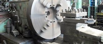
Universal 3 is a lathe with a standard layout and operating principle. The workpiece is clamped and rotated at a controlled speed. During the rotation process, a cutter is brought to it, which cuts into the metal and removes a certain layer of it.
This scheme has proven itself well, and manufacturers do not deviate from it unnecessarily.
The functions of the machine in question are to perform a variety of jobs that fit the definition of turning:
- Processing of external and internal cylindrical, conical and shaped surfaces.
- Boring holes to a given diameter.
- Trimming ends, chamfering and dulling sharp edges.
- Segment.
- Drilling small holes. In this case, unlike a drilling machine, the part rotates, and the drill is held motionless in the tailstock.
- Thread cutting. Automation of the process increases its accuracy and reduces the requirements for worker qualifications.
Each operation requires the appropriate tool. The level of production and compliance with the drawing directly depends on the correct choice of cutter.
In addition to the basic configuration, special equipment is used that adds such types of processing as:
- Grinding.
- Polishing.
- Milling of various planes.
- Sharpening of tools (both machining and household).
- Sawing with a circular saw or jigsaw blade.
- Planing.
- Winding of cylindrical springs.
- Thread cutting using hand tools. This uses spindle rotation.
- Additional equipment allows you to significantly save on equipment that is periodically needed.
TIP: A modernized version is the Universal-3m table lathe. It stands out with more power and works with comparable geometry.
Design features of the machine
Appearance
Structurally, it is made in a desktop version. Machines of the Universal series are used for turning metal products by rotating them and influencing the surface of cutting tools. Based on this condition, the equipment has optimal parameters typical for amateur equipment.
The machine does not have an original layout. Its main components and parts can be replaced with similar ones, which greatly simplifies repair and maintenance. The frame is made by casting, and the main components are located on it - the lead screw necessary for the longitudinal displacement of the caliper, the electric motor mounting bracket, the front and tailstocks.
Design features of the desktop model Universal-3:
- the main components are made of high-quality aged cast iron;
- It is possible to change the direction of movement of the caliper. In this case, there is no need to stop the spindle or change its direction of rotation;
- the elements are enclosed in a hollow cylindrical guide. Thanks to this, the likelihood of chips getting into the mechanism is reduced, and the degree of safety of working on the machine is also increased;
- the use of additional accessories is provided that increase the functionality of the equipment.
It is worth saying more about additional components. The standard package includes two types of tool holder - movable and fixed. The first is necessary for the formation of conical surfaces. Clamping reliability is ensured by collet elements installed in the tool holder and spindle head.
A milling and drilling device can be used to form holes. It is mounted on the caliper.
Specifications
Universal-3 is noticeably different from previous versions in terms of its performance. Its technological capabilities have increased and the range of acceptable workpiece sizes has expanded.
Key parameters:
- Accuracy class: N.
- Overall dimensions (determined by the extreme points): 675 mm x 410 mm x 280 mm. Most industrial tables fit these dimensions. When choosing a surface, it is necessary to consider the load distribution and the additional influence of vibration.
- Weight: 60 kilograms.
- Limit values for workpiece dimensions: diameter 90 mm (when located above the support) or 150 mm (when located above the frame) and length up to 250 mm (when fixed in the centers).
- Holder: up to 8 mm by 8 mm. Usually they use the usual GOST tool, but if desired, you can choose an imported one, which will provide better accuracy and durability.
- Diameter of holes produced by drilling: up to 6mm.
- Cones: Morse No. 2 (on the spindle) and No. 1 (on the tailstock).
- Number of direct rotation stages: 9 (from 200 rpm to 3200 rpm).
- Cartridge: 80 mm.
- Displacement of the transverse slider by one limb mark: 0.05 mm (longitudinal) and 0.05 (transverse). Working caliper feeds: from 0.05 to 0.175 mm per revolution.
- Thread pitch when cutting: from 0.2 to 2.5. Type: metric.
- Quill extension: up to 30 mm.
- Electric motor with a power of 0.37 kW. Required power supply voltage: 220 V. This corresponds to the parameters of a household network.
It is possible to process not only parts made of metal alloys, but also those made of wood (wood has its own technological features and its own tools) and plastic.
IMPORTANT: A more detailed list of features, description of parameters and characteristics are given in the passport. The kinematic and electrical diagrams are also depicted and deciphered there.
Purpose and scope
The Universal -3M desktop machine is designed for processing medium and small workpieces in individual workshops. Such a mechanism can often be found in the offices of schools, institutes, and various colleges.
Perfect for home use. the main advantages are:
- small amount of noise;
- the ability to connect to a household electrical network;
- small dimensions of the machine;
- its versatility.
That is why the device is popular among various craftsmen. The machine is designed to perform the following operations:
- segment;
- boring holes of different diameters;
- drilling holes and chamfering;
- grooving and boring of various surfaces, cylindrical, conical.
This is one of the most popular turning devices among modern turners of all levels.
Device
Any Universal metal lathe must meet several requirements, and it is these that determine the design. First, you need to ensure reliable clamping of the workpiece with minimal runout. For the range of products under consideration, a standard cartridge or centers without additional devices is quite sufficient. Secondly, it is necessary to reduce the amount of vibration of the equipment itself that occurs during operation. Thirdly, it is important that the feed is uniform, accurate and varies from relatively large (for rough turning) to minimal (for finishing with high dimensional accuracy)
The main parts of the Universal table machine (included in the turning configuration):
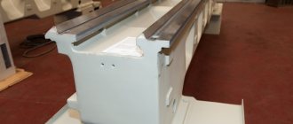
- Durable frame. This is the most massive component, guaranteeing the strength of the entire structure and its stability.
- Drive that sets the rotation. A fairly powerful motor is used, capable of providing a large feed when cutting.
- The headstock is spindle. Torque is transmitted to the spindle using a belt drive and pulleys and is adjusted in steps. To cut threads, rotation is transmitted to the longitudinal lead screw through gears. Changing the feed parameters changes the pitch.
- Rear grandma.
- Electrical system.
- Caliper with carriage. It is moved, both through the engagement of gears and manually.
For a rotary device, the length of the shaft does not matter much, and you can always change the modes of movement.
Manufacturer information
The direct developer of this machine is the Experimental Research Institute of Metal-Cutting Machine Tools.
The manufacturer, from 1932 to this day, is the Moscow Machine Tool Plant. The first designs were based on the Austrian analogue of the Unimat SL.
The primary version of the Station Wagon series had two guides. The 3M station wagon, unlike the first models, has been significantly improved and instead of two guides, it has one of a larger diameter, which is located in the middle of the frame.
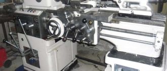
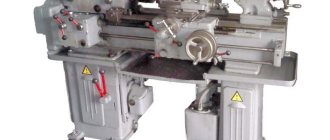
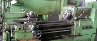
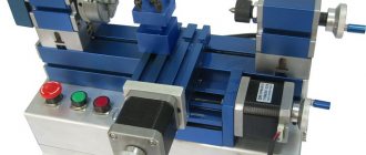
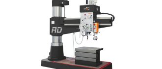
General view of the Universal-3M lathe
Photo of the Universal-3M lathe
Photo of the Universal-3M lathe
Photo of the Universal-3M lathe
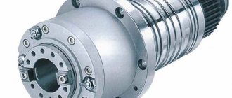
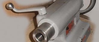
End of the spindle of the Universal-3M lathe
Photo of a guitar lathe Universal-3M
Photo of the Universal-3M lathe drive
Description of the operation of the electrical circuit of the Universal-3M lathe
Electrical equipment is powered from a single-phase alternating current network with a voltage of 220 V and a frequency of 50 Hz.
Starting and stopping the electric motor is carried out using the KV relay (see Fig. 14), which is controlled by the SB2 (start) and SB1 (stop) buttons. When starting, the KV relay turns on and becomes self-powered, connecting the electric motor to the network with its contacts and providing zero protection, i.e. turning off the electric motor when there is no voltage in the network. The electric motor is protected from overload by the start-up relay A, which breaks the starting circuit, which turns off the KV relay. Restarting is possible only after 15-50 s, i.e. after the thermal protection elements of the start-up relay A return to their original position.
When starting the electric motor, its starting torque increases due to the connection of the starting capacitor C1 by the contacts of the start-protective relay A in parallel with the running capacitor C2. After the electric motor accelerates and the starting current decreases, capacitor C1 is turned off.
Reversing the electric motor is carried out using the switch SA, which, with the middle (vertical) position of the handle, ensures that the electric motor is turned off, i.e. it stops even when the KV relay is turned on. The handle should be left in a neutral position
Description of the kinematic diagram of the Universal-3M screw-cutting lathe
Main drive chain
In this circuit, the spindle rotates from electric motor 3 through a V-belt drive (see Fig. 3). There are 9 operating spindle speeds.
Two stages (200 and 300 rpm) can be obtained if pulley 13, rigidly seated on the electric motor shaft, is connected by a belt to intermediate pulley 1, and that, in turn, along the stream “a” - with pulley 2, freely rotating relative to the electric motor shaft . From pulley 2 along one of two free streams - “b” or “c” - rotation is transmitted directly to pulley 9, rigidly connected to the spindle.
One stage (650 rpm) is obtained by transmitting rotation from pulley 13 directly to pulley 9, bypassing intermediate pulleys 1 and 2.
Two more stages (525 and 1000 rpm) can be obtained if a replacement pulley 12 is put on pulley 13 so that the end on which there are cams faces outward. From pulley 12, as in the first case, rotation is transmitted to intermediate pulley 1, and from it along stream “b” to pulley 2, which transmits rotation to pulley 9 along streams “a” or “c”.
The remaining four stages (1200, 1700, 2800 and 3200 rpm) are obtained if the electric motor shaft is connected to pulley 2 through pulley 12 using cams located at one of the ends of the latter. Now, along any of the four streams, rotation can be transferred to pulley 9.
Note: The 1200 rpm stage can be obtained without connecting the motor shaft to pulley 2.
Feed drive chain
The caliper is moved to the right and left using lead screw 14.
Rotation is transmitted to the lead screw directly from the spindle by a gear II rigidly attached to it.
Through gear 10, rotation is transmitted to gears 8 and A, then to the intermediate roller 5. There are two options for transmitting rotation to this roller: the first option (indicated by number I in the diagram) - through a block of gear wheels B-B and wheel D, and the second (indicated by number II in the diagram) - through gears B and C.
The first option is used for feeding during normal turning, the second - when cutting threads. A gear wheel 6 is rigidly connected to the roller 5. From this wheel to the wheel 7, mounted on the left end of the lead screw, rotation can be transmitted either through a pair of gear wheels 15 and 16 - and then the caliper will move to the left, or through the gear wheel 17, which will ensure moving the caliper to the right. All three wheels (15, 16 and 17) are mounted on the rotating device 4 (see D-D) and are in constant engagement with the gear wheel 6 (central). Thus, it is possible to move the caliper both to the right and to the left with the same direction of spindle rotation.
It is also possible to disable the support feed without stopping the spindle rotation. This is ensured by disengaging gears II and 10 using the same rotary device 4 and spring 18.
ATTENTION! To avoid breaking the gears of the feed drive chain, switching on and switching the direction of movement of the support should be done with the spindle not rotating.
The movement of the tailstock quill and the transverse movement of the caliper are carried out by handwheels through the corresponding screw pairs, as shown in the kinematic diagram.
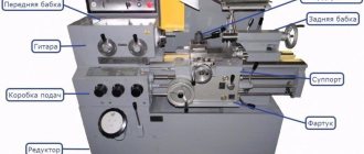
Location of controls for the Universal-3M lathe
Location of controls for the Universal-3M lathe
List of controls for the Universal-3M screw-cutting lathe
- feed movement control handle (turning on mechanical longitudinal feed of the caliper to the left, right and turning it off)
- main movement control handle (turning on forward rotation of the spindle, stopping and turning on reverse rotation)
- handwheel for transverse caliper movement
- toolholder movement handwheel
- quill clamp handle
- quill movement handwheel
- handwheel for longitudinal movement of the caliper
- button to turn off the power to the electrical equipment of the machine (red)
- power button for the electrical equipment of the machine (black)
Machine device
When considering the Universal 2 benchtop lathe, you should pay attention to its layout. The device consists of the following elements:
- The bed acts as a load-bearing element that connects all the nodes together. It is made of cast iron and is characterized by high rigidity. This ensures precise positioning of all nodes relative to each other, as well as vibration damping at the time of processing.
- Round guides are welded to the base. They are required to move the main units. The latest version of the equipment has only one guide, but it ensures precise positioning of the units at the time of movement.
- With the exception of the latest model, on the first and second models the headstock is removable and fastened with special bolts.
- An electric motor is installed on the frame. A stepped belt drive is used as a drive. It is worth considering that the electrical circuit of the Universal 2 lathe is quite simple; the electric motor and drive can be removed from the device.
- The cross support is represented by a carriage, longitudinal and transverse slides. This unit fixes the tool in the required position at the time of processing. The cross support is characterized by high versatility in use and is suitable for securing tools with a rectangular holder. The tool can be offset relative to the workpiece by a certain angle if necessary.
- The Universal 3 lathe in question also has a tailstock, which is required to secure the workpiece in the required position. In most cases, a center is fixed in it to support the workpiece when it is long.
- Replacement guitar speed gears are designed to drive the caliper feed. They are selected when cutting threads with different parameters. The guitar comes with a combination of four or three interchangeable gears with terminal clamps. There are also instructions for setting up the device to obtain the required thread.
- The number of revolutions at the output is changed by a belt drive. This element also eliminates the possibility of motor overheating in the event of a spindle jam.
- Electrical control unit.
- Longitudinal lead screw. It is designed to ensure movement of the carriage along the workpiece.
- There is also a stand that, if necessary, can be mounted during drilling work.
- Handles and other controls. In order to ensure the required control accuracy, steering wheels and handles are installed. You can control the electrical part using various keys.
- Collet clamp for securing cutters and drills. The model under consideration can be used for various milling operations, for which the appropriate equipment and tools are installed. However, the number of milling operations performed is significantly limited.
- The table is rectangular.
The location of a fairly large number of different components on a small frame determines that the Universal can be used for a wide variety of work. The layout of the Universal is classic, due to which there are no problems with setting up and installing the workpiece.
The layout features also determine what types of work can be carried out on a lathe. The list of operations is as follows:
- Turning works, rough and finishing.
- Grinding and drilling.
- Processing the workpiece with a jigsaw or circular saw.
- Jointing in case of installation of wooden blanks.
- Sharpening operations.
An important point is that it is quite simple to re-adjust the equipment for drilling work; all you need to do is unfasten the mounting screws. After this, a vertical support is installed, which is used to mount the electric drive with the remaining necessary components.
Electrical equipment of the Universal-3M lathe. General information
According to the method of protection against electric shock, the electrical equipment of the machine belongs to class I, i.e. has working insulation, an element for grounding and a wire with a grounding conductor for connection to the power source and grounding.
The basic electrical diagram of the machine is shown in Fig. 14, the list of electrical equipment elements is in Table 4. Electrical equipment is located in a separate box (see Fig. 1, item 6). The box is closed with a lid. The cover is secured with two screws, one screw is located in the center of the cover under the rubber mat, the other secures the cover to the frame, ensuring the cover is grounded.