A transformer is a unit designed to transmit electricity with changed parameters through the network to the end consumer. This equipment has a specific design. Transformers can step down or step up voltage.
Over time, the core may need to be rewinded. In this case, the radio amateur is faced with the question of how to wind the transformer. This process takes a lot of time and requires concentration. However, there is nothing complicated about rewinding a circuit. There are step-by-step instructions for this.
Design
The transformer operates on the principle of electromagnetic induction. It may have a different magnetic drive design. However, one of the most common is the toroidal coil. Its design was invented by Faraday. To understand how to wind a toroidal transformer or a device of any other design, you must first consider the design of its coil.
Toroidal devices convert alternating voltage from one power to another. There are single-phase and three-phase designs. They consist of several elements. The structure includes a ferromagnetic steel core. There is a rubber gasket, primary and secondary winding, as well as insulation between them.
The winding has a screen. The core is also covered with insulating material. A fuse and fasteners are also used. To connect the windings into a single system, a magnetic drive is used.
Winding device
Toroidal transformers can be of different types. This must be taken into account during the contour creation process. You can wind a transformer 220/220, 12/220 or other varieties using a special tool.
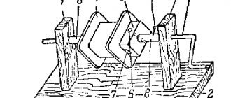
To simplify the process, you can make a special device. It consists of wooden posts that are fastened together with a metal rod. It has the shape of a handle. This skewer will help you quickly wind the outlines. The twig should be no thicker than 1 cm. It will pierce the frame right through. Using a drill will make this process easier.
The drill is mounted on the surface of the table. It will be parallel. The handle should rotate freely. The rod is inserted into the drill chuck. Before this, you need to put a block with the frame of the future transformer on the metal pin. The rod may have a thread. This option is considered preferable. The block can be clamped on both sides using a nut, textolite plates or wooden planks.
Other tools
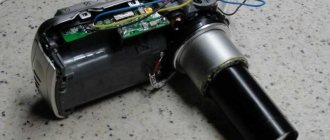
To wind a 12/220, pulse, ferrite or other types of transformer, you need to prepare a few more tools. Instead of the design presented above, you can use an inductor from a telephone, a device for rewinding film, or a machine for a bobbin with thread. There are many options. They must ensure a smooth, uniform process.
You will also need to prepare the device for unwinding. In principle, such equipment is similar to the devices presented above. However, in the reverse process, rotation can be performed without a handle.
In order not to count the number of turns yourself, you should purchase a special device. It will take into account the number of turns on the coil. An ordinary water meter or bicycle speedometer may be suitable for these purposes. Using a flexible roller, the selected metering device is connected to the winding equipment. You can count the number of turns of a coil orally.
How to calculate the number of turns of the primary winding?
We enter the initial data obtained in the previous paragraphs into the calculator form and obtain the number of turns of the primary winding. By changing the size of the ring, the grade of ferrite and the generation frequency of the converter, you can change the number of turns of the primary winding.
It should be noted that this is a very, very simplified calculation of a pulse transformer.
But, the properties of our wonderful self-excited power supply are such that the converter itself adapts to the parameters of the transformer and the load size by changing the generation frequency. So, as the load increases and the transformer tries to enter saturation, the generation frequency increases and the operation returns to normal. Minor errors in our calculations are compensated in the same way. I tried to change the number of turns of the same transformer by more than one and a half times, which is reflected in the examples below, but I could not detect any significant changes in the operation of the power supply, except for a change in the generation frequency.
Calculations
To understand how to wind a pulse transformer, it is necessary to make calculations. If you are rewinding an existing coil, you can simply remember the original number of turns and purchase a wire of identical cross-section. In this case, you can do without calculations.
But if you need to create a new transformer, you need to determine the quantity and type of materials. For example, for a device with a working load from 12 to 220 V, a device with power from 90 to 150 W will be required. You can take a magnetic drive, for example, from an old TV. The conductor cross-section is determined in accordance with the power of the unit.
The number of turns of the coils is determined for 1V. This figure is equivalent to 50 Hz. The primary (P) and secondary (B) windings are calculated as follows:
- P = 12 x 50/10 = 60 turns.
- B = 220 x 50/10 = 1100 turns.
To determine the currents in them, the following formula is used:
- Tp = 150: 12 = 12.5 A.
- TV = 150: 220 = 0.7 A.
The obtained result must be taken into account when choosing materials for creating a new device.
Direction of turns
I had difficulty finding information about the direction of the winding turns - for this I had to refresh my school physics course (the gimlet rule, etc.). Although this question inevitably arises for a beginner.
The main rule is that the direction of the winding turns does not matter
... as long as there is a need to connect the windings to each other (series or parallel), or in the case of using a transformer in some devices where the phase of the signal is important.
It doesn’t matter in which direction you wind the turns - what matters is how the windings are then connected
Series connection of windings
When connecting the windings of a transformer in series, you need to mentally imagine that one winding is a continuation of the other, and the point of their connection is a break in a single winding
, in which
the direction of rotation of
the turns around the core remains unchanged (and of course cannot turn in the opposite direction!).
In this case, any terminal of the winding can be the beginning or the end, and the direction of rotation itself can be any. The main thing is that this direction remains the same for the connected windings.
In this case, the movement of the connected windings from top to bottom of the coil or from bottom to top does not matter (see the figure - enlarged by clicking the mouse).
In transformers in which the core is shaped like the letter “O” and the coils are wound on two frames on the right and left, the same rules apply. But for ease of understanding, you can mentally “tear” the core (from above or below), and imagine that it is straightened into one rod - this will make it easier to understand how one winding passes into another while maintaining the direction of rotation of the turns (clockwise or counterclockwise) . See the picture below (the picture can be enlarged by clicking the mouse).
Parallel connection of windings
When connecting in parallel, the length of the wire in the windings is important.
Even with the same number of turns, different windings may have different wire lengths (the winding that is closer to the middle will be shorter, and the one further away will be longer). As a result, cross-flows
.
If parallel connection of the windings is assumed, then it is better to wind them simultaneously in two (three, four...) wires. Then they will be the same length, which will eliminate cross-flows as much as possible during their further parallel connection.
Winding several wires is also used in the absence of a wire of the required cross-section (a large cross-section is collected with several smaller wires).
Checking the direction of turns using a battery and a multimeter
If you have a transformer in which you need to connect two windings in series, but the direction of the turns is not visible or known, you can apply a DC pulse from a battery to one of the windings, observing the voltage surge on the other winding.
When the voltage surge at the moment of connecting the battery on the multimeter (on the second winding) is in “+”, then the connection points of the windings will be any “+” and “-” of different windings (for example, “+” of the multimeter and “-” of the battery, or vice versa) . The other two ends will be the outputs of these windings after connection (see figure - click to enlarge).
Direction of turns on different coils
I repeat - the direction of winding is not important, it is the connection of the windings that is important.
There is one “but” though. If we talk about convenience, then on this type of transformer (with a core in the shape of the letter “O” and two coils), it is more convenient to wind the right and left coils in the same way (not mirrored, but identically). In this case, it will be more convenient to install jumpers when connecting two windings in series on different coils - the jumpers will be on one side, and not across the entire frame from top to bottom.
See the picture (to enlarge, click on the picture):
Layer insulation
To wind a ferrite transformer or other type of device, you need to study one more nuance. Insulation materials should be installed between certain layers of conductors. Most often, condensate or cable paper is used for this. All necessary materials can be purchased in specialized stores. The paper must have sufficient density and be smooth without gaps or holes.
Between the individual coils, insulating layers are created from stronger materials. Lacquered fabric is most often used. It is covered with paper on both sides. This is also necessary to level the surface before winding. If you couldn’t find varnished fabric, you can use paper folded in several layers instead.
The paper is cut into strips, the width of which should be greater than the outline. They should extend beyond the edges of the winding by 3-4 mm. Excess material will be folded up. This will keep the edges of the reel well protected.
Frame
To understand how to properly wind a transformer, you should pay attention to every detail of this process. Having prepared the insulation, wire and tools, you should make a frame. You can use cardboard for this. The inside of the frame must be larger than the core rod.
For an O-shaped magnetic drive, you need to prepare 2 coils. For an W-shaped core, one circuit will be required. In the first option, the round core must be covered with an insulating layer. Only after this do they begin winding.
If the magnetic drive is W-shaped, the frame is cut out from the sleeve. Brushes are cut out of cardboard. In this case, the coil will need to be wrapped in a compact box. The brushes are put on the sleeves. Having prepared the frame, you can begin winding the conductor.
Frame for transformer
The transformer frame (or inductor) is needed to isolate the windings from the core and to keep the windings, insulating gaskets and terminals in order. Therefore, it must be made of sufficiently strong insulating material. At the same time, it must be made of a sufficiently thin material so as not to take up much space in the core window.
Typically, the material for the frame is thick cardboard (pressboard), fiber, textolite, getinaks, etc. Depending on the size of the transformer or inductor, the thickness of the sheet material for the frame is taken from 0.5 to 2.0 mm.
To glue the cardboard frame, you can use office universal glue or regular wood glue. The best glue with good moisture resistance should be considered nitro glue (enamel, rolled oats). Getinax or textolite frames are usually not glued together, but assembled “into a lock”.
Fig. 6. Proportionality of the frame and core plates. a - for split plates; b - for plates with a perforation of the middle core.
Based on the dimensions of the core, the shape and dimensions of the frame are determined, after which its parts are drawn and then cut. If transformer plates with a middle core cut are used, then the height of the frame is made several millimeters less than the height of the window so that the core plates can be inserted without difficulty.
To avoid errors, the dimensions of the core plates must be carefully measured (if they are unknown) and a sketch drawn on paper with the dimensions of individual parts of the frame. It is especially important to coordinate the individual parts of the frame when assembling it “into a castle”. The ratios of the dimensions of the frame and core plates for different types of plates are given in Fig. 6.
Fig. 7. Cutting and gluing the frame for the transformer.
A regular frame for a transformer can be made like this. First, the cheeks of the frame are cut out and a sleeve with cuffs on the end sides is cut out according to Fig. 7. Having made cuts at the folds, the pattern is rolled into a box, with side 1 glued to side 5. After that, both cheeks are put on the sleeve.
Then you need to bend the flaps of the sleeve and, spreading the cheeks to the edges of the sleeve, glue the flaps to the outer planes of the cheeks. You can glue pieces of the same cardboard from which the frame sleeve was made into the corners on the outside of the cheeks. If the glue is strong and reliable enough, then the sleeve can be made without flaps, gluing the cheeks directly to the edges of the sleeve.
Fig. 8. Details of the prefabricated frame for the transformer. a is the width of the core plate, plus the gap, plus the thickness of the material of parts 3; b - the thickness of the set of core plates plus the thickness of parts 2; in is the thickness of the material.
The prefabricated frame is more difficult to manufacture, but it has great strength and does not require gluing. Details of the prefabricated frame are shown in Fig. 8.
They are manufactured as follows. The dimensions from the sketch are transferred by marking to a sheet of material (textolite, getinax, fiber). If the material is not too thick, then the parts are cut out with scissors.
Then the grooves are cut into them using a file. In cheeks 1, after drilling several holes in them, windows are cut out.
Fig. 9. Assembling the frame for the transformer coils into a lock.
After this, having laid out the parts on the table, they adjust sides 2 and 3 of the sleeve so that when assembling the frame, all the cuts and protrusions of the “lock” come together. When marking and manufacturing parts 2, one of them can have a “key” part that is much larger in size (the contours are shown in dotted lines in Fig.
 for placing contacts or petals on it for soldering the winding leads. To avoid confusion of parts, they should be numbered before assembly. The order of assembly of the frame is clear from Fig. 9.
Immediately after making the cheeks, it is better to pre-drill holes for the leads in them “as a reserve”. When assembling the frame or gluing the cheeks, it is necessary to take into account which side of the transformer (or both) and which side of the cheeks the leads will be made in order to correctly position the sides of the cheeks that have holes for the leads.
It is necessary to pay attention to the fact that the sides of the cheeks with holes in the case of a square core section are not covered by the core plates.
The finished glued or assembled frame must be prepared for winding, for which you should round off the corners of the sleeve and cheeks with a file, and also remove burrs. It is useful (but not necessary) to coat or impregnate the frame with shellac, bakelite, etc.
Step-by-step winding instructions
Winding the transformer with your own hands will be quite simple. To do this, a reel of wire should be installed in the unwinding equipment. The old wire will be removed from it. The frame of the future transformer must be placed in the winding equipment. Then you can make rotational movements. They should be measured, without jerking.
During this procedure, the wire from the old coil will be moved to the new frame. The distance between the wire and the table surface should be at least 20 cm. This will allow you to place your hand and fix the cable.
You need to lay out all the necessary tools and equipment on the table in advance. You should have insulating paper, scissors, sandpaper, a soldering iron (plugged into the mains), a pen or pencil on hand. With one hand you need to turn the handle of the winding device, and with the other you need to fix the conductor. It is necessary that the turns are laid evenly and evenly.
Features of winding pulse transformers.
Winding pulse transformers, and especially transformers on ring and toroidal magnetic cores, has some features.
The fact is that if any winding of the transformer is not distributed evenly enough around the perimeter of the magnetic circuit, then individual sections of the magnetic circuit may become saturated, which can lead to a significant reduction in the power of the power supply and even lead to its failure.
It would seem that you can simply calculate the distance between the individual turns of the coil so that the turns of the winding fit exactly into one or several layers. But, in practice, winding such a winding is difficult and tedious.
We are trying to wind a “lazy winding”. And in this case, the easiest way is to wind a single-layer winding “turn to turn”.
What is needed for this?
It is necessary to select a wire of such a diameter that it fits “turn to turn”, in one layer, into the window of the existing ring core, and even so that the number of turns of the primary winding does not differ much from the calculated one.
If the number of turns obtained in the calculator does not differ by more than 10-20% from the number obtained in the formula for calculating the laying, then you can safely wind the winding without counting the turns.
True, for such winding, most likely, you will need to choose a magnetic circuit with a slightly higher overall power, which I already advised above.
1 – ring core.
3 – winding turns.
D is the diameter by which you can calculate the perimeter occupied by the turns of the winding.
The picture shows that when winding “turn to turn”, the calculated perimeter will be much smaller than the internal diameter of the ferrite ring. This is due to both the diameter of the wire itself and the thickness of the gasket.
In fact, the actual perimeter that will be filled with wire will be even smaller. This is due to the fact that the winding wire does not adhere to the inner surface of the ring, forming some gap. Moreover, there is a direct relationship between the diameter of the wire and the size of this gap.
You should not increase the tension of the wire when winding in order to reduce this gap, since this can damage the insulation and the wire itself.
Using the empirical formula below, you can calculate the number of turns based on the diameter of the existing wire and the diameter of the core window.
The maximum calculation error is approximately –5% + 10% and depends on the density of the wire.
w = π(D – 10S – 4d) / d , where:
w – number of turns of the primary winding,
π – 3,1416,
D – internal diameter of the ring magnetic core,
S – thickness of the insulating gasket,
d – diameter of wire with insulation,
/ - fractional line.
How to measure the diameter of a wire and determine the thickness of the insulation is described here.
Recommendations about winding
When considering step-by-step instructions on how to wind a transformer, you should pay attention to subsequent operations. After laying the conductor, the frame will need to be insulated. Through its hole it is necessary to pass the end of the wire removed from the circuit. The fixation will be temporary.
Experienced radio amateurs recommend practicing first before winding. When you can apply the turns evenly, you can start working. The tension angle and wires must be constant. Each subsequent layer does not need to be wound all the way. Otherwise, the conductor may slip from its intended place.
During the winding process, you need to set the counter to zero. If it is not there, you need to pronounce the number of turns of the wire out loud. At the same time, you should concentrate as much as possible so as not to lose count.
The insulation will need to be pressed with a soft rubber ring or glue. Each subsequent layer will be 1-2 turns less than the previous one.
How to choose ferrite ring core?
You can select the approximate size of a ferrite ring using a calculator for calculating pulse transformers and a guide to ferrite magnetic cores. Both can be found in the “Additional Materials”.
We enter the data of the proposed magnetic core and the data obtained in the previous paragraph into the calculator form to determine the overall power of the core.
You should not choose ring dimensions close to the maximum load power. It is not so convenient to wind small rings, and you will have to wind a lot more turns.
If there is enough free space in the body of the future design, then you can choose a ring with a obviously larger overall power.
I had at my disposal an M2000NM ring of standard size K28x16x9mm. I entered the input data into the calculator form and received an overall power of 87 watts. This is more than enough for my 50 Watt power supply.
Launch the program. Select “Calculation of a half-bridge transformer with a master oscillator.”
To prevent the calculator from “swearing”, fill in the windows not used for calculating the secondary windings with zeros.
Connection process
When considering how to wind a transformer, it is necessary to study the process of connecting the wires. If the core breaks during winding, the soldering process should be performed. This procedure may also be required if you initially plan to create a circuit from several separate pieces of wire. Soldering is performed in accordance with the thickness of the wire.
For wire up to 0.3 mm thick, the ends need to be cleared to 1.5 cm. They can then simply be twisted and soldered using the appropriate tool. If the wire is thick (more than 0.3 mm), you can solder the ends directly. In this case, twisting is not required.
If the wire is very thin (less than 0.2 mm), it can be welded. They are twisted without undergoing a stripping procedure. The connection point is brought into the flame of a lighter or alcohol lamp. An influx of metal should appear at the junction. The junction of the wires must be insulated with varnished cloth or paper.
Obtaining initial data for simple calculation of a pulse transformer.
I remember when our power grids had not yet been privatized by foreigners, I built a switching power supply. The work dragged on until night. During the last tests, it suddenly turned out that the key transistors began to get very hot. It turned out that the network voltage jumped to 256 Volts at night!
Of course, 256 Volts is too much, but you shouldn’t rely on GOST 220 +5% –10% either. If you choose 220 Volts +10% as the maximum network voltage, then:
242 * 1.41 = 341.22V (we count the amplitude value).
341.22 – 0.8 * 2 ≈ 340V (subtract the drop on the rectifier).
We determine the approximate value of induction from the table.
Example: M2000NM – 0.39T.
The generation frequency of a self-excited converter depends on many factors, including the size of the load. If you choose 20-30 kHz, you are unlikely to make a big mistake.
Limit frequencies and induction values of widespread ferrites.
Manganese-zinc ferrites.
| Parameter | Ferrite grade | |||||
| 6000NM | 4000NM | 3000NM | 2000NM | 1500NM | 1000NM | |
| Cutoff frequency at tg δ ≤ 0.1, MHz | 0,005 | 0,1 | 0,2 | 0,45 | 0,6 | 1,0 |
| Magnetic induction B at Hm = 800 A/m, T | 0,35 | 0,36 | 0,38 | 0,39 | 0,35 | 0,35 |
Nickel-zinc ferrites.
| Parameter | Ferrite grade | |||||
| 200NN | 1000NN | 600NN | 400NN | 200NN | 100NN | |
| Cutoff frequency at tg δ ≤ 0.1, MHz | 0,02 | 0,4 | 1,2 | 2,0 | 3,0 | 30 |
| Magnetic induction B at Hm = 800 A/m, T | 0,25 | 0,32 | 0,31 | 0,23 | 0,17 | 0,44 |
Trial
Having studied the procedure on how to wind a transformer, you should consider a few more recommendations. The number of turns of a thin conductor can reach several thousand. In this case, it is better to use special counting equipment. The winding is protected from above with paper. For thick conductors, external protection is not required.
Next, the operation of the transformer is tested. Its primary circuit is connected to the network. A lamp is connected in series to the power source. This will allow you to identify a short circuit.
To assess the reliability of the insulation, it is necessary to touch each output of the network circuits with the lead-out conductor in turn. The verification procedure must be performed very carefully. Avoid the possibility of electric shock.
After reviewing the step-by-step instructions for winding a transformer, you can repair an old one or create a new device. If all its points are strictly followed, it is possible to create a reliable, durable unit.