§ 45. Calculation of conductor resistance. Resistivity
We know that the cause of the electrical resistance of a conductor is the interaction of electrons with ions of the metal crystal lattice (§ 43). Therefore, it can be assumed that the resistance of a conductor depends on its length and cross-sectional area, as well as on the substance from which it is made.
Figure 74 shows the setup for conducting such an experiment. Various conductors are included in the current source circuit in turn, for example:
- nickel wires of the same thickness, but different lengths;
- nickel wires of the same length, but different thicknesses (different cross-sectional areas);
- nickel and nichrome wires of the same length and thickness.
The current in the circuit is measured with an ammeter, and the voltage with a voltmeter.
Knowing the voltage at the ends of the conductor and the current in it, using Ohm's law, you can determine the resistance of each of the conductors.
Rice. 74. Dependence of conductor resistance on its size and type of substance
After performing these experiments, we will establish that:
- of two nickel wires of the same thickness, the longer wire has greater resistance;
- of two nickelin wires of the same length, the wire with a smaller cross-section has the greater resistance;
- Nickel and nichrome wires of the same size have different resistances.
Ohm was the first to study experimentally the dependence of the resistance of a conductor on its size and the substance from which the conductor is made. He found that resistance is directly proportional to the length of the conductor, inversely proportional to its cross-sectional area and depends on the substance of the conductor.
How to take into account the dependence of resistance on the material from which the conductor is made? To do this, calculate the so-called resistivity of the substance.
Specific resistance is a physical quantity that determines the resistance of a conductor made of a given substance with a length of 1 m and a cross-sectional area of 1 m2.
Let us introduce the letter designations: ρ is the resistivity of the conductor, I is the length of the conductor, S is its cross-sectional area. Then the conductor resistance R will be expressed by the formula
From it we get that:
From the last formula you can determine the unit of resistivity. Since the unit of resistance is 1 ohm, the unit of cross-sectional area is 1 m2, and the unit of length is 1 m, then the unit of resistivity is:
It is more convenient to express the cross-sectional area of the conductor in square millimeters, since it is most often small. Then the unit of resistivity will be:
Table 8 shows the resistivity values of some substances at 20 °C. Specific resistance changes with temperature. It has been experimentally established that for metals, for example, the resistivity increases with increasing temperature.
Table 8. Electrical resistivity of some substances (at t = 20 °C)
Of all the metals, silver and copper have the lowest resistivity. Therefore, silver and copper are the best conductors of electricity.
When wiring electrical circuits, aluminum, copper and iron wires are used.
In many cases, devices with high resistance are needed. They are made from specially created alloys - substances with high resistivity. For example, as can be seen from Table 8, the nichrome alloy has a resistivity almost 40 times greater than aluminum.
Porcelain and ebonite have such a high resistivity that they almost do not conduct electric current at all; they are used as insulators.
Questions
- How does the resistance of a conductor depend on its length and cross-sectional area?
- How to experimentally show the dependence of the resistance of a conductor on its length, cross-sectional area and the substance from which it is made?
- What is the resistivity of a conductor?
- What formula can be used to calculate the resistance of conductors?
- In what units is the resistivity of a conductor expressed?
- What substances are conductors used in practice made from?
Strength of materials
Numerous experiments by scientists have shown that the resistance of a conductor depends not only on its properties, but also on its linear characteristics. These results were confirmed by analyzing the flow of electric current. You can do it yourself by constructing your reasoning as follows.
Let there be a conductor of length L, which is connected in parallel to a voltage source. Then a potential difference (voltage) equal to U will be created at its ends. An electric current with force I will flow through the material under the action of an eclectic field. To determine the resistance of the conductor, you need to use Ohm’s law, according to which: R 1 = U / I.
Now you can take a material similar in properties to the first one, but twice as long. Let this conductor also be connected to the power source. In this case, a current equal in strength to I will pass through it. Mentally, the conductor can be divided into 2 sections along L. This means that the electric current will first flow through its first half, and then through the second.
Current is the directional movement of charges. For them to begin their movement, the field needs to do work. Thus, the sequential charge passes through 2 halves of the material. For both parts, the voltage will be equal to U. The total work performed will be 2 times greater compared to the first case. This means that a voltage of 2U will arise at the ends of the second conductor. That is: R2 = 2U / I = 2* R1.
From the above it follows that the resistance of the conductor is directly proportional to the length. Similar considerations can be made by changing the cross-sectional area. As a result, it turns out that R will be inversely proportional to it. The dependence of the resistance can be written as follows: R ~ L / S. The proportionality coefficient does not depend on the linear dimensions of the conductor, but only on the material from which it is made; for strict equality, a parameter called resistivity was introduced into the formula: R = ρ * L / S.
Coefficient ρ is a characteristic of the material. From here we can write: ρ = R* S/ L, where:
- R is the electrical resistance of a homogeneous conductor;
- S—cross-sectional area;
- L is the length of the material.
The physical meaning of the resistivity of a conductor is the resistance of a homogeneous material made from this substance with a unit length and cross-sectional area. In SI, the value is measured in [Ohm * m]. Knowing it and its dimensions, finding the resistance of the conductor will not be difficult.
Tags
Obstetrics Antinociceptive effect Brucellosis Herds Monetary valuation of land Land cadastre TICK Cyst Narisna geometry Pasteurellosis Sexual cycle Sales of grain Salmonellosis Mating Tuberculosis Tuberculin Territory arrangement abortion actinomycosis fleas soil grading grain vibration gynecology document yeast vibration efficiency va stallion livestock weeding land use tick mowing mating mt land assessment paratyphoid soil anti-erosion market grain self-warming sperm table wines dry wines chemistry tests cervix endometritis
Dependence of conductor resistance on length, cross-sectional area and material.
Based on experiments, it was found that the resistance of a conductor is directly proportional to its length and inversely proportional to its cross section
Where p is the proportionality coefficient, or the resistivity of the conductor, I is the length of the conductor, S is the cross-section of the conductor.
Specific resistance is the resistance of a conductor of a given substance of unit length and unit cross-section. The resistivity of a conductor depends on the material of the conductor.
The SI unit of resistivity is
Dependence of conductor resistance on temperature
The resistance of conductors depends on temperature. The value characterizing the dependence of the change in the resistance of a conductor on temperature is called the Temperature coefficient of resistance and is denoted by A. The temperature coefficient of resistance shows by what part of the initial resistance the resistance of this conductor changes when heated from 0 ° C to G C, that is
From this formula you can get the units of temperature coefficient of resistance
Having made the appropriate transformations, we get
The resistance of all metals increases when heated; their temperature coefficients of resistance are positive. The resistance of solutions of salts, acids, alkalis, as well as coal decreases when heated, their temperature coefficients are negative, for them the formula for the dependence of resistance on temperature can be written as follows:
In formula (1), replacing
We obtain the general formula for resistance
Where p0 is the resistivity of the conductor at 0° C. If in formula (2) we replace
Then we get
Where Pt is the resistivity of the conductor at temperature t° C.
Superconductivity.
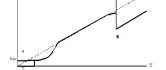
As the temperature of pure metals approaches absolute zero, their resistance sharply drops to zero (Fig. 77).
The current flowing through a closed conductor, at temperatures close to absolute zero, can circulate in it for quite a long time. This phenomenon is called Superconductivity.
We advise you to study Calculation of LED aquarium lighting
Temperature dependence ρ(T)
For most materials, numerous experiments have been carried out to measure resistivity values. Data for most conductors can be found in reference tables.
Specific resistance of metals and alloys, Ohm*mm2/m
(at T = 20C)
| Silver | 0,016 | Bronze (alloy) | 0,1 |
| Copper | 0,017 | Tin | 0,12 |
| Gold | 0,024 | Steel (alloy) | 0,12 |
| Aluminum | 0,028 | Lead | 0,21 |
| Iridium | 0,047 | Nickelin (alloy) | 0,42 |
| Molybdenum | 0,054 | Manganin (alloy) | 0,45 |
| Tungsten | 0,055 | Constantan (alloy) | 0,48 |
| Zinc | 0,06 | Titanium | 0,58 |
| Brass (alloy) | 0,071 | Mercury | 0,958 |
| Nickel | 0,087 | Nichrome (alloy) | 1,1 |
| Platinum | 0,1 | Bismuth | 1,2 |
Most often, the values of ρ are given at normal, that is, room temperature 20C. But it turned out that with increasing temperature, the resistivity increases linearly in accordance with the formula:
$ ρ(T) = ρ0 * (1 + α*T)$ (6),
where: ρ is the resistivity of the conductor at a temperature of 0C, α is the temperature coefficient of resistivity, which also has its own individual meaning for each substance. From formula (6) it follows that the coefficient α has dimension or .
Rice. 2. Temperature dependence of conductor resistivity
In accordance with the Joule-Lenz law, when an electric current flows, heat is released, which means the temperature of the conductor increases. In addition, depending on the area of application, electrical devices can operate at both low (minus) and high temperatures. For accurate calculations of electrical circuits, it is necessary to take into account the dependence ρ(T). The value of α for a specific material can be found in reference literature.
We advise you to study How to test a resistor with a multimeter
Rice. 3. Reference values of the temperature coefficient of resistivity of conductors
What does the resistance of a metal depend on?
Electric current, according to the classical definition, is the directed movement of charged particles. Electrons move in metals if a potential difference is created between two points of connection of a power source. This process is hindered by impurities, so conductivity is better in a homogeneous material.
For your information. High-quality current conductors are made from electrical copper, which contains no more than 0.01% of foreign impurities. A slight addition of aluminum (0.02-0.03%) reduces conductivity by 10-11%. With a large route length, energy transmission losses increase significantly.
Vibrational processes of the atoms of the crystal lattice have a negative impact. As the temperature rises, the amplitude of these movements increases, which creates additional obstacles to the movement of charges. To compensate for this phenomenon, resistors are made from special alloys. Properly selected proportions of materials ensure stability of electrical resistance in the designed temperature range.
Formula how to find
According to the provision from any textbook on electrodynamics, the resistivity of the conductor material formula is equal to the proportion of the total resistance of the conductor per cross-sectional area divided by the conductor length
It is important to understand that the final indicator will be influenced by temperature and the degree of material purity. For example, if you add a little manganese to copper, the overall indicator will increase several times
Main calculation formula
Interestingly, there is a formula for inhomogeneous isotropic material. To do this, you need to know the electric field strength with the electric current density. To find it, you need to divide the first quantity by the other. In this case, the result is not a constant, but a scalar quantity.
There is another, more difficult to understand formula for an inhomogeneous anisotropic material. Depends on the tensor coordinate.
It is important to note that the relationship between resistance and conductivity is also expressed by formulas. There are rules for finding isotropic and anisotropic materials through tensor components
They are shown in the diagram below.
Relationship with conductivity expressed in physical relations
Conditions that determine conductor resistance
When determining resistance, a number of characteristics are taken into account:
- element section;
- conductor length;
- resistivity;
- material type.
Objects with high resistance practically do not conduct current. There is also an inverse relationship, which is spelled out in Ohm's law. To calculate the indicator, electrical conductivity is taken into account. It shows the ability of a conductor to accept electric current.
Conductivity of electric current
Selecting cable cross-sections
For large calculations, you can use a specialized calculator on the help site or appropriate software. The following algorithm is used to sequentially calculate operating parameters using the formulas:
- when transmitting power P = 1,600 W to a connected load in a line with a voltage U = 220 V, direct current (I) is determined as follows: I = P/U ≈ 7.27 A;
- resistance of a copper conductor (in both directions) with a length of 800 m and a cross-section of 2.5 mm square: R = (2*I*p)/S = (2*800*0.0175)/2.5 = 11.2 Ohm ;
- voltage losses in this path: ΔU = (2*L*I)/((1/p)*S) = (2*800*7.27)/((1/0.0175)*2.5) = 11,520/ 142.86 = 80.63 V.
If necessary, the last expression can be easily converted mathematically to select the cross-sectional area of the conductor based on the total value of the connected load:
S = (2*I*L)/((1/p)*ΔU.
In the example considered, the voltage loss is more than 36%. This result indicates the need to adjust the calculation of conductor resistance. According to current standards, it is permissible to reduce the control parameter by no more than 5%. By increasing the diameter of the wire, you can get the desired result. With a cross section of 19 mm square. the voltage will decrease to 209.41 V (4.81%).
Taking into account the increased resistance of the aluminum wire, proportional changes in losses are assumed. By performing a similar calculation, you can get a recommended cross-section of 31 mm square. The use of such a conductor under similar conditions will reduce the voltage to 209.2 V, which will ensure compliance with the standards - 4.92%.
For your information. You can use a multimeter to check the calculated data. Measurements are performed in the appropriate range, taking into account the amplitude of the signal, alternating (direct) current.
Measuring cable resistance with a multimeter
When connecting an AC power source, the calculation algorithm becomes more complicated. For such initial conditions, use the formula:
ΔU = ((Pa * Ra + Pр * Ri) *L)/ U,
Where:
- Pa (Pр) – active (reactive) power;
- Ra (Ri) – relative active (inductive) resistance of the line in Ohms per kilometer.
For certain conductor materials, the initial data is taken from the reference book. By analogy with the mentioned standards, the voltage reduction should generally not be more than 5%. Additional restrictions are applied taking into account the characteristics of electrical networks and connected consumers (from 1% to 12%). The current rules are clarified according to the text of the latest edition of the PUE.
The above calculation results convincingly confirm the advantages of lower resistivity of copper wire. When using an aluminum analogue, the amount of material for transmitting electricity with standard losses increases significantly. For a comprehensive analysis, the best indicators of copper in terms of strength and flexibility should be taken into account.
Aluminum is less expensive and lightweight. But when working with this material, vibration effects and movements during operation should be excluded. Bends are designed with particular care to maintain the integrity of the conductor. Electrical contact is disrupted by the formation of oxides on the surface of products made from this metal.
For your information. In certain situations, free space for laying the route will mean a lot. In terms of space saving, copper has the advantageous parameters.
Selection of conductor cross-section based on permissible heating
As the current increases, the temperature of the conducting metal increases. At a certain level, the protective insulation layer made of polymers is damaged. This causes short circuits and flame formation. Dangerous situations are prevented by correct calculation of the cross-sectional area. The method of laying (joint/separate) has a certain significance.
Selection of cable products taking into account heating
Selection of cross section based on voltage loss
As shown in the calculations, with a long route length it is necessary to take into account the voltage reduction and the corresponding energy losses. In large projects, the entire current circuit with switchgear and connected loads is considered.
Selection based on acceptable losses
To accurately determine suitable cable products, the characteristics of the operating process are considered. They make the necessary reserves to prevent emergency situations when connecting new consumers and voltage surges in the power supply network.
Kinds
A conductor is a medium or object that is capable of conducting electric current. Inside it, when connected to an energy source, a charged particle begins to actively move. An ammeter shows the increase in electrical voltage in a circuit. When considering different types of conductors, the electrical conductivity and type of material are taken into account:
- copper;
- aluminum;
- metal;
- gold;
- an alloy of nickel and chromium.
You may be interested in this Designation wat
In the scientific community there is the concept of a superconductor, which is considered ideal. It has a significant dielectric loss angle. When current flows from a circuit, the percentage of bias is taken into account. For a superconductor, this parameter is minimal.
From copper
Copper belongs to the components of group 11 from the table of chemical elements. According to the classification, it is lamellar and is found in different types. Often the substance has a pink tint. In electrical engineering, copper has a low resistivity and shares a niche with silver and gold.
Silver and gold
The material is applicable in the manufacture of wiring and printed circuit boards. Another substance is in demand in the manufacture of electric drives. Considering complex controlled electromechanical systems, it is noticeable that they use windings with low resistivity.
If we evaluate power transformers, they also use this metal, but it is often used with impurities. This is necessary to reduce the electrical conductivity rate. In printed circuit boards, copper is used in tandem with aluminum. When considering radio components, copper-based alloys, which are also characterized by low resistance, remain in demand.
When disassembling personal computers, the substance is found in bronze or brass. Zinc or nickel additives are also used. To increase the elasticity of the conductor, other materials are used, such as tin and zinc. According to the resistivity table, the substance is assigned an indicator of 0.0157 Ohm.
Properties of copper
Made of aluminum
Among the elements of group 13 in the table, aluminum stands out. It is an excellent conductor in a circuit and is made of paramagnetic metal. The color has a silvery tint. The conductor lends itself well to mechanical processing. In addition to significant electrical conductivity, corrosion resistance is noted.
During heat treatment, an oxide film is formed that protects the surface. There are various aluminum compounds found in nature. If we consider standard wire of small cross-section, it is in demand in electric coils. The substance has low density and mass, so analogues are difficult to find. Using aluminum in moving parts can improve their performance.
The conductor is often found in hard drives and audio systems. Wires coated with a layer of varnish remain in demand. There are enameled analogues that are characterized by increased security. Rubber and beryl are used as insulation. Manufacturers produce conductors with a cross section of 0.003 mm.
Properties of aluminum
In addition to inductors, wire can be installed in inductors, loudspeakers, and headphones. Regarding connections, there are options with alunites. Additional information about physical properties:
- low melting point;
- high heat capacity;
- significant hardness;
- weak paramagnetic;
- wide temperature range.
You may be interested in this Features of the cross section
Aluminum is found in printed circuit boards because it can be stamped. Corrosion resistance is an added benefit. Aluminum conductors are popular and in demand in industry. Resistivity - 0.028 Ohm. It is also necessary to consider the disadvantage of a significant content of impurities.
Made of metal
Among metals, the following are considered common types of conductors:
- lead;
- tin;
- platinum;
- nickel;
- tungsten.
Lead is a group 14 element that can be used as a conductor. It has a maximum density of 11.35 grams per cubic meter. The scope of application is limited because the material is toxic and belongs to heavy metals. The history of the origin of the formula is unclear, there are only guesses.
Metal groups
If we talk about conductor elements, lead nitrate is often used. In power sources and backup units there is a version with chloride. Considering inorganic compounds, the material that stands out is telluride. It is suitable as a thermoelectric conductor and is therefore used in power plants of various capacities. The metal element is also in demand in refrigerators.
If we consider telluride in detail, a significant dielectric constant should be attributed to one of the features. In addition to lead, it contains tin and tellurium. Separately, the substances are found in photoresistors and diodes. If you disassemble semiconductor devices, the elements are contained in stabilizers and indicate the direction of current.
Important! Tin is a conductor from group 14 of chemical elements. The material is safe and does not contain toxic substances.
Along with gold, tin has excellent anti-corrosion properties. Disulfide is often used in technology. Tin dioxide shows the highest resistance value. In batteries it is used in its pure form. When considering galvanic cells, it is worth mentioning manganese-tin dioxide.
Platinum is a conductor from the tenth group of chemical elements. The presented metal has an electrical resistance of 0.098 Ohms and is characterized by increased density. If we consider the scope of application, the substance is often found in laser technology. We are talking about printers, as well as measuring instruments.
Properties of platinum
Additionally, platinum is used in electromagnetic relays. In the presented automatic devices it acts as a conductor. We are talking about mechanical, thermal or optical relays. In electronic sensors, platinum is contained in smaller quantities, but is used due to its wide temperature range. In particular, you can consider an electronic resistance thermometer. The resistive element is mostly made of platinum.
You may be interested in this Features of free energy
From gold
The resistivity of gold is 0.023 Ohm. The material belongs to the first group of metals and is soft in physical properties. Gold can also be found in pure form with impurities. The density is 19.32 g/cm³, the scope of application is wide. In industry, the conductor is in demand as solder.
Solder gold
It can be applied to various surfaces and serves as an excellent material for joining workpieces due to its low melting point. Gold is also in demand for protection against corrosion.
Flaws:
- softness of the material;
- subject to pitting corrosion.
If you use a material with additives, the melting point decreases. This also affects the mechanical properties of the substance.
Gold with additives
Resistivity of various metals
To calculate the losses that a certain length of conductor provides, it is convenient to operate with specific parameters. Basic formula for calculating electrical resistance:
R = p*(L/S),
Where:
- L – length in meters;
- S – cross-sectional area, mm2;
- p – specific resistance of a cable made of a certain material, (Ohm*mm sq.)/m.
If necessary, the cross-section can be calculated by diameter (D) using the well-known formula from geometry:
S = (π * D2)/4.
If a micrometer is not available, wind the wire around a cylindrical tool (screwdriver, pencil). Next, measure the length of the created coil with a regular ruler and divide the resulting value by the number of turns.
Copper and aluminum
A minimal amount of impurities is sufficient to significantly change the wire resistance. However, even with a high degree of purification, copper conducts electricity much better than aluminum. Below are the resistivity values of the corresponding materials. Using reference information, it is easy to check losses when choosing cable products to form a route of a certain length:
- pm = 0.0175;
- pa = 0.028.
We advise you to study Converting a screwdriver to lithium 18650 batteries
Other metals
The resistivity of nichrome ranges from 1.04 to 1.42 (Ohm*mm sq.)/meter. The large scatter of parameters is explained by a proportional change in the components of the alloy. Such materials are used to create heating elements, since the integrity of the products is maintained at high temperatures. Given the high resistance of nichrome wire per unit length, this cable is ideal for creating a “warm floor”.
Features of other materials (resistivity Ohm*mm sq.)/m):
- gold (0.023) provides good conductivity and oxidation resistance, but is expensive;
- the limited use of silver (0.015) is also explained by the high price;
- the high melting point (+3,422°C) of tungsten (0.05) allows it to be used for the manufacture of spirals of classic incandescent lamps;
- constantan (0.5) is used to create resistors.
How to calculate resistance
Experimental data on a large number of samples showed that:
- Resistance R is inversely proportional to the transverse area of the sample S, that is, $ R ∼ {1\over S } $;
- Resistance R is directly proportional to the length of the sample, that is, the longer the length of the sample L, the greater its resistance, that is, $ R∼ L$;
- Since the values of R for samples from different materials with the same dimensions S and L were different, a new physical quantity was introduced, called electrical resistivity ρ.
The data obtained were well described by the formula:
$ R = ρ * {L\over S} $ (2).
From equation (2) follows the formula for electrical resistivity:
$ ρ = R * { S \over L } $ (3).
The values of ρ for most substances can be found using reference books in printed or electronic form.
Rice. 2. Table of electrical resistivities of various substances at a temperature of 200C.
Geometry Dependency
From the section describing the specific parameters it is clear that the electrical resistance of the conductor depends on the length. If we take a silver sample (standardized cross-sectional area 1 sq. mm) with a length of 6.8 m, it is easy to calculate the value R = 6.8 * 0.016 = 0.1088 Ohm.
Other practical problems are solved in a similar way. To create a wire with an electrical resistance of 100 Ohms, you will need a silver wire 6,250 m long = 100/0.016. If we use a metal conductor made of iron, the length will be 833 m = 100/0.12.
The next decisive factor is the cross-sectional area. For clarity, you can use the example of pumping liquid from the main tank into two different containers. It is easy to create the necessary pressure by raising the main tank to a small height. By using tubes with different duct diameters, you can see the difference in the rate of filling of control volumes. If the readings are measured, if desired, it is easy to create proportional dependencies taking into account the initial geometric parameters of the transport channels.
The size of the conductors also matters. Electrical resistance (R) is equal to the specific value for a particular material (Rsp), multiplied by the length (L) and divided by the corresponding cross-section (S). If only the diameter is known, then for a round core you can apply the classic formula from a school geometry course:
S = (π * d2)/4 = (3.14 * d2)/4.
The length is calculated using the converted expression:
L = S * (R/ Rsp).
These proportions demonstrate what resistance depends on.
Electrical resistance and conductivity
March 26, 2013. Category: Electrical engineering.
When an electrical circuit is closed, at the terminals of which there is a potential difference, an electric current occurs. Free electrons, under the influence of electric field forces, move along the conductor.
In their movement, electrons collide with the atoms of the conductor and give them a supply of their kinetic energy.
The speed of electron movement continuously changes: when electrons collide with atoms, molecules and other electrons, it decreases, then under the influence of an electric field it increases and decreases again during a new collision.
As a result, a uniform flow of electrons is established in the conductor at a speed of several fractions of a centimeter per second. Consequently, electrons passing through a conductor always encounter resistance to their movement from its side. When electric current passes through a conductor, the latter heats up.
Electrical resistance
The electrical resistance of a conductor, which is denoted by the Latin letter r, is the property of a body or medium to convert electrical energy into thermal energy when an electric current passes through it.
In the diagrams, electrical resistance is indicated as shown in Figure 1, a.
| Figure 1. Symbol for electrical resistance |
Variable electrical resistance that serves to change the current in a circuit is called rheostat . In the diagrams, rheostats are designated as shown in Figure 1, b.
In general, a rheostat is made of a wire of one resistance or another, wound on an insulating base.
The slider or rheostat lever is placed in a certain position, as a result of which the required resistance is introduced into the circuit.
A long conductor with a small cross-section creates a large resistance to current. Short conductors with a large cross-section offer little resistance to current.
If you take two conductors from different materials, but the same length and cross-section, then the conductors will conduct current differently. This shows that the resistance of a conductor depends on the material of the conductor itself.
The temperature of the conductor also affects its resistance. As temperature increases, the resistance of metals increases, and the resistance of liquids and coal decreases. Only some special metal alloys (manganin, constantan, nickel and others) hardly change their resistance with increasing temperature.
So, we see that the electrical resistance of a conductor depends on: 1) the length of the conductor, 2) the cross-section of the conductor, 3) the material of the conductor, 4) the temperature of the conductor.
The unit of resistance is one ohm. Om is often represented by the Greek capital letter Ω (omega). Therefore, instead of writing “The resistance of the conductor is 15 ohms,” you can simply write: r = 15 Ω. 1,000 Ohms is called 1 kiloohm (1kOhm, or 1kΩ), 1,000,000 Ohms is called 1 megaohm (1mOhm, or 1MΩ).
When comparing the resistance of conductors from different materials, it is necessary to take a certain length and cross-section for each sample. Then we will be able to judge which material conducts electric current better or worse.
1. Conductor resistance
Electrical resistivity
The resistance in ohms of a conductor 1 m long, with a cross-section of 1 mm² is called resistivity and is denoted by the Greek letter ρ (rho).
Table 1 shows the resistivities of some conductors.
Table 1
Resistivities of various conductors
| Conductor material | Specific resistance ρ in |
| Silver Copper Aluminum Tungsten Iron Lead Nickelin (alloy of copper, nickel and zinc) Manganin (alloy of copper, nickel and manganese) Constantan (alloy of copper, nickel and aluminum) Mercury Nichrome (alloy of nickel, chromium, iron and manganese) | 0,016 0,0175 0,03 0,05 0,13 0,2 0,42 0,43 0,5 0,941,1 |
The table shows that an iron wire with a length of 1 m and a cross-section of 1 mm² has a resistance of 0.13 Ohm. To get 1 Ohm of resistance you need to take 7.7 m of such wire. Silver has the lowest resistivity.
1 Ohm of resistance can be obtained by taking 62.5 m of silver wire with a cross section of 1 mm². Silver is the best conductor, but the cost of silver excludes the possibility of its mass use. After silver in the table comes copper: 1 m of copper wire with a cross section of 1 mm² has a resistance of 0.0175 Ohm.
To get a resistance of 1 ohm, you need to take 57 m of such wire.
Chemically pure copper, obtained by refining, has found widespread use in electrical engineering for the manufacture of wires, cables, windings of electrical machines and devices. Aluminum and iron are also widely used as conductors.
The conductor resistance can be determined by the formula:
where r is the conductor resistance in ohms; ρ – conductor resistivity; l – conductor length in m; S – conductor cross-section in mm².
Example 1. Determine the resistance of 200 m of iron wire with a cross section of 5 mm².
Example 2. Calculate the resistance of 2 km of aluminum wire with a cross section of 2.5 mm².
From the resistance formula you can easily determine the length, resistivity and cross-section of the conductor.
Example 3. For a radio receiver, it is necessary to wind a 30 Ohm resistor from nickel wire with a cross section of 0.21 mm². Determine the required wire length.
Example 4. Determine the cross-section of 20 m of nichrome wire if its resistance is 25 Ohms.
Example 5. A wire with a cross section of 0.5 mm² and a length of 40 m has a resistance of 16 Ohms. Determine the wire material.
The material of the conductor characterizes its resistivity.
Based on the resistivity table, we find that lead has this resistance.
It was stated above that the resistance of conductors depends on temperature. Let's do the following experiment. Let's wind several meters of thin metal wire in the form of a spiral and connect this spiral to the battery circuit.
To measure current, we connect an ammeter to the circuit. When the coil is heated in the burner flame, you will notice that the ammeter readings will decrease.
This shows that the resistance of a metal wire increases with heating.
For some metals, when heated by 100°, the resistance increases by 40–50%. There are alloys that change their resistance slightly with heating.
Some special alloys show virtually no change in resistance when temperature changes.
The resistance of metal conductors increases with increasing temperature, while the resistance of electrolytes (liquid conductors), coal and some solids, on the contrary, decreases.
The ability of metals to change their resistance with changes in temperature is used to construct resistance thermometers. This thermometer is a platinum wire wound on a mica frame. By placing a thermometer, for example, in a furnace and measuring the resistance of the platinum wire before and after heating, the temperature in the furnace can be determined.
The change in the resistance of a conductor when it is heated, per 1 ohm of initial resistance and per 1° temperature, is called the temperature coefficient of resistance and is denoted by the letter α.
If at temperature t0 the resistance of the conductor is equal to r0, and at temperature t is equal to rt, then the temperature coefficient of resistance
Note. Calculation using this formula can only be done in a certain temperature range (up to approximately 200°C).
We present the values of the temperature coefficient of resistance α for some metals (Table 2).
table 2
Temperature coefficient values for some metals
| Metal | α | Metal | α |
| Silver Copper Iron TungstenPlatinum | 0,0035 0,0040 0,0066 0,00450,0032 | Mercury Nikelin Constantan Nichrome Manganin | 0,0090 0,0003 0,000005 0,000160,00005 |
From the formula for the temperature coefficient of resistance we determine rt:
rt = r0 [1 ± α (t – t0)].
Example 6. Determine the resistance of an iron wire heated to 200°C, if its resistance at 0°C was 100 Ohms.
rt = r0 [1 ± α (t – t0)] = 100 (1 + 0.0066 × 200) = 232 Ohm.
Example 7. A resistance thermometer made of platinum wire in a room with a temperature of 15°C had a resistance of 20 ohms. The thermometer was placed in the oven and after some time its resistance was measured. It turned out to be equal to 29.6 Ohms. Determine the temperature in the oven.
Electrical conductivity
So far, we have considered the resistance of a conductor as the obstacle that the conductor provides to the electric current. But still, current flows through the conductor. Therefore, in addition to resistance (obstacle), the conductor also has the ability to conduct electric current, that is, conductivity.
The more resistance a conductor has, the less conductivity it has, the worse it conducts electric current, and, conversely, the lower the resistance of a conductor, the more conductivity it has, the easier it is for current to pass through the conductor. Therefore, the resistance and conductivity of a conductor are reciprocal quantities.
From mathematics we know that the reciprocal of 5 is 1/5 and, conversely, the reciprocal of 1/7 is 7. Therefore, if the resistance of a conductor is denoted by the letter r, then the conductivity is defined as 1/r. Conductivity is usually symbolized by the letter g.
Electrical conductivity is measured in (1/Ohm) or in siemens.
Example 8. The conductor resistance is 20 ohms. Determine its conductivity.
If r = 20 Ohm, then
Example 9. The conductivity of the conductor is 0.1 (1/Ohm). Determine its resistance
If g = 0.1 (1/Ohm), then r = 1 / 0.1 = 10 (Ohm)
Active resistance of wires and cables
It is known from electrical engineering that the total resistance under equal conditions to alternating and direct current will differ. This also applies to wires and cables. This is due to the fact that the alternating current is distributed unevenly across the cross section (surface effect). However, for wires made of non-ferrous metals and with an alternating voltage frequency of 50 Hz, this effect does not have too much influence and can be neglected. Thus, when calculating conductors made of non-ferrous metals, their resistance to alternating and direct current is assumed to be equal.
In practice, the active resistance of copper and aluminum conductors is calculated using the formula:
Where: l – length in km, γ – specific conductivity of the wire material m/ohm∙mm2, r – active resistance of 1 km of wire per phase Ohm/km, s – cross-sectional area, mm2.
The value r is usually taken from reference tables.
The active resistance of the wire is also affected by the ambient temperature. The value of r at temperature Θ can be determined by the formula:
Where: α – temperature coefficient of resistance; r20 – active resistance at a temperature of 20 C, γ20 – specific conductivity at a temperature of 20 C.
Steel wires have significantly higher active resistance than similar wires made of non-ferrous metals. Its increase is due to a significantly lower specific conductivity and the surface effect, which is much more pronounced in steel wires than in aluminum or copper. Moreover, in steel wires there are losses of active energy due to eddy currents and magnetization reversal, which is taken into account in equivalent circuits of lines as an additional component of active resistance.
The active resistance of steel wires (unlike wires made of non-ferrous metals) strongly depends on the amount of current flowing, so it is impossible to use a constant value of specific conductivity in calculations.
It is very difficult to analytically express the active resistance of steel wires depending on the flowing current, so special tables are used to determine it.
Resistivity Units
From equation (3) it follows that in the International SI system the unit of measurement for ρ will be (Ohm*m), since resistance is measured in ohms, and length and area are measured in meters and square meters, respectively. That is, the unit of resistivity is equal to the resistance of a sample with an area of 1 m2 and a length of 1 m. But in practice, this unit turned out to be not very convenient due to too large numerical values. Therefore, for electrical calculations, a non-system unit (Ohm*mm2/m) is more often used, for which the cross-sectional area is taken in mm2. The characteristic cross-sectional dimensions of connecting wires and cables are in the range of 1-15 mm2, which explains the ease of use of the off-system unit.
Aluminum wires are resistant to corrosion, have a low resistivity of 0.026 (Ohm*mm2/m) and low weight per meter of length, which makes this material very popular in the manufacture of wires and cables operating outdoors. The disadvantage of pure aluminum wiring is the loss of strength (integrity) when bending and twisting. A solution to this problem was found by weaving into the wires of high-voltage power lines a small amount of conductive steel threads that have high strength ratings for all types of loads. This is especially important during strong gusts of wind and when ice forms on wires in winter.
Calculation of conductor resistance
Simplified methods that need to be adjusted taking into account real conditions were discussed above. Thus, temperature has a significant effect on the conductivity of materials. In serial conductors (copper, aluminum), the value of this parameter increases in the proportion of 0.3-0.5% for each degree. In carbon-based compositions and electrolytes, the opposite effect is observed - a decrease in resistance.
Without holding strings or other devices for tricks, real levitation using superconductivity is provided
The experiment shown in the figure can be reproduced by lowering the temperature of the metal to “absolute zero” (-273°C). With such extreme cooling, the atomic lattice is fixed in a stable position.
This state creates ideal conditions for the movement of electrons. The absence of obstacles is accompanied by minimal losses, which explains the promising direction for creating efficient energy transmission lines. The example in the figure demonstrates improved operational parameters of transport communications. In this case, friction forces can be eliminated.
Combination of airless tube and superconductivity improves performance of advanced transport systems
It is clear that to improve economic performance it is necessary to increase the operating temperature while maintaining good conductivity. However, the latest scientific achievements in the relevant field allow us to count on positive results in the near future.
It should be emphasized! In practice, different computing technologies may be needed. For example, the material is unknown. It is difficult to identify it by external signs. For high-quality chemical laboratory analysis, in addition to the appropriate skills, special equipment is required.
However, if necessary, it is easy to derive the specific indicator:
Rsp = R * S / L.
Geometric parameters are measured with standard tools (ruler, caliper). According to a typical measurement scheme, electrical resistance is determined using a multimeter. To calculate Rsp, use the formula presented above. In the directory, select the position corresponding to the calculation result. Using the same technique, you can determine other unknown values, for example, the length of the cable in an underground route.
In actual calculations, the reactive components of the conductors are taken into account to improve accuracy. For example, the inductance of a long straight line is determined by the formula:
AND = (m0/2π) * L *(mc * ln(L/r) +1/4m,
Where:
- m – magnetic permeability of the material (o – constant, c – environment);
- r and L are the radius and length of the conductor, respectively.
As the frequency increases, it is necessary to take into account current spreading in the surface zone and vortex changes.
The theoretical knowledge presented will be useful for calculating and creating a rheostat - a device with adjustable resistance. They are needed to prevent electrical injuries using precise calculations of protective circuits and specialized circuit breakers (fuses).
We advise you to study the UGO Standard
Concept of electrical resistance of a conductor
The classical definition explains electric current by the movement of “free” (valence) electrons. It is provided by the electric field created by the source. Movement in the metal is hampered not only by the normal components of the crystal lattice, but also by defective areas, impurities, and inhomogeneous areas. During collisions with obstacles, due to the transition of momentum into thermal energy, the temperature increases.
A good example is heating water with a boiler.
In gases, electrolytes and other materials the physics of the phenomenon is somewhat different. Linear relationships are observed in metals and other conductors. The basic relationships are expressed by the well-known formula of Ohm's law:
R (electrical resistance) = U (voltage) / I (current).
For convenience, the inverse quantity, conductivity (G = 1/R), is often used. It denotes the ability of a certain material to pass current with certain losses.
We advise you to study the Force Measuring Device
To simplify, the example of a water pipe is sometimes used. A moving fluid is an analogue of a current. Pressure is the equivalent of voltage. By decreasing (increasing) the cross section or position of the locking device, the conditions of movement are determined. In a similar way, the basic parameters of electrical circuits are changed using resistance (R).
For your information. The amount of liquid passing per unit time through the control section of the pipe is the equivalent of electrical power.
Changes in conductor with increasing length
During tests, it was noticed that as the length of the conductor increases, its electrical resistance increases. To conduct the experiment, it is necessary to select blanks from the same material. For example, it could be nickel wire. To read the parameters, an ammeter is used, which is connected to the terminals.
By installing workpieces of shorter length, it is noted that the current in the circuit increases. Even on one product you can play with the ammeter. By placing the probe in the middle of the workpiece, for example, a value of 50 amps may be displayed.
Ammeter reading
Interesting! If you move it to the side, towards the edge, to increase the range of the holder, the current indicator will decrease. The same applies to conductors made of other materials.
Dependence on voltage properties
After a simple transformation of the basic formula, you can create the correct expression for voltage:
U = I * R.
The current source generates electricity. The connected resistor consumes energy and is converted into heat. To maintain a certain current strength, it is necessary to set the appropriate voltage.
Measuring circuit, graphs
The graphs show the current-voltage characteristics of different devices. The first two demonstrate linear dependencies in which only the angle of inclination of the straight line changes (depending on the electrical resistance of the resistor).
If you connect a semiconductor diode, the graph will change significantly. From the figure, one can determine the low resistance in the region of positive values of U. However, after a change in polarity, an increase in negative voltage is not accompanied by a similar change in current. One-way conduction is, in particular, used to rectify signals.
In the last graph, the shifted zero current transition point indicates the EMF of the power source. As in the previous example, a small angle relative to the vertical indicates a low internal resistance of the battery.
Dependence on voltage properties
Voltage is the main driving force of electricity. Tension is primary. In fact, this is an environment in which various processes associated with electric current occur. The most important thing is the connection between electric current and the electromagnetic field. And its parameters, in turn, are determined not only by voltage, but also by the spatial and geometric characteristics of the conductor.
Even in the case when the conductor is a straight piece of wire as part of an electrical circuit, its position in space at sufficiently high voltage frequencies will noticeably affect the value of its resistance. This is due to the fact that under these conditions its inductance and capacitance appear, which exist only at alternating voltage. These conductor parameters are called reactance, and also lead to electricity losses.
Therefore, if a conductor is exposed to alternating voltage, its resistance also depends on both the frequency of this voltage and its inductive-capacitive parameters.
The active joint venture remains in effect. The resistance of a conductor as a whole is called impedance. It is usually denoted by the letter Z and calculated using complex numbers. These are quite specific calculations, which should not bore the reader of our article. But so that the reader does not doubt this statement, we further present the formula by which impedance is generally calculated:
Formula
What are the types of electric current in everyday life?
The shape of the current signal depends on the operation of the voltage source and the resistance of the medium through which the signal passes. Most often in practice, a home craftsman has to deal with the following types:
- a constant signal generated from batteries or galvanic cells;
- sinusoidal, created by industrial generators with a frequency of 50 hertz;
- pulsating, formed by transformations of various power supplies;
- pulsed, penetrating into the household network due to lightning discharges into overhead power lines;
- arbitrary.
The most common type is sinusoidal or alternating current: it powers all our devices.
What is voltage in the electricity network.
Voltage is a physical quantity that characterizes an electric field. In other words, it shows how much work it does when moving one positive charge a certain distance.
Voltage indicator on a voltmeter
The unit of voltage in the international system is taken to be such an indicator at the ends of a conductor at which a charge of 1 C does 1 J of work to move it along this conductor. The generally accepted unit of measurement for voltage is 1 V - Volt.
Important! Work is measured in Joules, charges in Coulombs, and voltage in Volts, so 1 Volt equals 1 Joule divided by 1 Coulomb. https://www.youtube.com/embed/AoQxuSGlFMQ
What it is
The resistivity of a conductor is a physical quantity that indicates that a material can resist electric current. In other words, this is the resistance of metals that a material with a unit cross section provides resistance to flowing current. DC resistivity differs in that it is caused by current flowing into the conductor. As for alternating current, it appears in a conductor under the influence of a vortex field.
Electrical resistivity
It is also important to clarify what electrical conductivity is. Electrical conductivity is a quantity that is the reciprocal of resistance and is called electrical conductivity
This is an indicator showing the measure of conductivity of electric current.
Note! The larger it is, the better the conductor is able to conduct electricity. General definition from the textbook
General definition from the textbook
What is electrical resistance?
It can be defined based on two positions. The first is related to the formula for Ohm's law. And it sounds like this: electrical resistance is a physical quantity that is defined as the ratio of the voltage in a conductor to the current flowing in it. The mathematical notation is given below.
The second is based on the properties of the body. The electrical resistance of a conductor is a physical quantity that indicates the ability of a body to convert electrical energy into heat. Both of these statements are true. Only in the school course they most often stop at memorizing the first. The quantity being studied is designated by the letter R. The units in which electrical resistance is measured are Ohms.
We advise you to study Stray Currents
Geometry Dependency
But direct current is not as simple as it appears from some experiments. It's all about his strength. It is known that the cross-sectional area is directly related to the current strength. But this pattern does not always apply. From certain strength values, the current increasingly rushes towards the surface of the conductor, which is called current displacement. For this reason, resistance to high current is less for flat and tubular conductors.
Current distribution across the diameter of the conductor
An even better result is obtained when coated with silver. High frequency currents manifest themselves similarly. For them, the surface effect is natural in the same way as for high-power direct current. But the mechanical force acting on the conductor can also affect its resistance. And this is not surprising, since deformations affect the distribution of particles that slow down electrons.
This principle is the basis of strain gauging, without which today it is impossible to imagine mechanical engineering and other industries where the strength of materials is important. All of the listed reasons on which the joint venture depends manifest themselves differently in different materials. But for the applied use of the relationship between resistance and certain influences, special alloys and chemical compounds have been developed.
Current distribution across the diameter of the conductor
But in any case, resistance is measured in Ohms and fractions of an Ohm, including multiples of 1000, that is, kilo-ohms, mega-ohms. Resistance, as a rule, does not exceed several units of megaohm. We tried to show readers several reasons behind the joint venture. We hope that the knowledge gained will help to successfully solve existing problems.