Information about the manufacturer of the screw-cutting lathe 16E16KP
The manufacturer of the 16E16KP screw-cutting lathe is the Yerevan Machine Tool Plant named after. Dzerzhinsky .
The plant produced screw-cutting lathes of models 1L61, 1B61, 1P61, 1V61, 1M61, a series of lathes 16L20, 16P16, 16E16. They also produced mechanized and special machines of the ET-23, ET-26, ET-34, ET-41 models, and a multi-cutting machine model ET-50.
Currently, the plant is called Yerevan Machine Tool Production Association ESPO , OJSC. The products produced are universal high-precision screw-cutting lathes 16E25P and 16EG25P with a processing diameter of 500 mm.
Machine tools produced by the Yerevan Machine Tool Plant named after. Dzerzhinsky
- 1B61
- 1М61 d=320mm
- 1М61П d=320mm
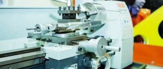
- 16E16KP high-precision screw-cutting lathe d=320mm
Lathe designation
1
— lathe (group number according to ENIMS classification)
6
– subgroup number (1, 2, 3, 4, 5, 6, 7, 8, 9) according to the ENIMS classification (6 - screw-cutting lathe)
E
– machine generation (A, B, C, D, E, K, L, M)
16
– height of centers above the bed 175 mm
Letters at the end of the model designation:
G
– a machine with a recess in the bed
TO
– machine with copying device
P
– machine accuracy - (n, p, v, a, s) according to GOST 8-82 (P - increased accuracy)
F1
– a machine with a digital display device (DRO) and preset of coordinates
F2
– machine with CNC positional numerical control system
F3
– machine with contour (continuous) CNC system
The screw-cutting lathe with an automatic transmission of increased precision 16E16KP is designed for performing a variety of turning operations, as well as for cutting metric, inch, modular and pitch threads.
The machine is designed to perform finishing turning operations of increased (P) accuracy.
The machine is intended for delivery both to the domestic market and for export, including to countries with a tropical climate. Type of climatic version UHL4 or 04 according to GOST 15150-69. Designation when ordering: 16E16KP-UHL4 or 16E16KP-04.
High precision and cleanliness of processing are ensured by the precision of manufacturing of all basic parts and the careful assembly of the machine, the use of high-precision bearings as spindle supports, the balancing of all fast-rotating parts of the machine, and a wide range of cutting speeds with stepless regulation.
It is necessary to take into account that the machine is a high-precision model, and in order to avoid loss of accuracy, it should not be used for roughing.
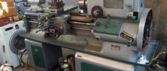
General layout and features of the machine
The bed is a cast iron box-shaped frame with transverse U-shaped ribs - it has two prismatic and two flat guides. The guides are subjected to heat treatment followed by grinding. The bed is installed on one stand. In the niche of the right end of the frame there is an electric motor for rapid movements of the carriage.
An automatic transmission is mounted on the rear wall at the left end of the cabinet, a lubrication station is located at the right end, and the main drive electric motor is located inside the cabinet.
In the niche of the right end of the cabinet there is a coolant reservoir and a cooling system pump.
The machine spindle 16e16kp receives 24 rotation speeds (10..2000 rpm). The spindle receives 12 rotation speeds directly from the gearbox through a V-belt drive and a balanced take-up pulley, and 12 rotation speeds through the selector gears (1:4, 1:16) of the headstock. To control the search, use the right handle on the headstock.
12 stages on the input shaft of the headstock are provided by the automatic transmission. The spindle rotation speed is set by handle 9 (see Fig. 3. Location of controls for a 16e16kp screw-cutting lathe) and two handles 14 and 15.
The front end of the spindle is flanged for quick change of the lathe chuck, made in accordance with GOST 12593 (DIN 55027, ISO 702-3-75) for a rotary washer, with a centering short cone:
- Nominal cone diameter D = 106.375 mm, nominal spindle end size - 6
- Internal (tool) spindle cone - Morse 6
- Standard diameter of the lathe chuck - Ø 200, Ø 250 mm, version - type 2 (for a rotary washer)
- The diameter of the through hole in the spindle is Ø 45 mm
- The largest diameter of the rod is Ø 44 mm
The headstock mechanism allows:
- cut threads with an increased pitch of 4 and 16 times
- cut right and left hand threads
- cut multi-start threads when working with cuts 1:4 and 1:16 with the number of starts 2, 3, 4, 5, 6, 10, 12, 15, 20, 30, and when working directly with the number of starts 2, 3, 4 , 6, 12
The feed box provides cutting of metric, inch, modular and pitch threads without the use of replaceable gears. To cut precise threads, the lead screw can be turned on directly, bypassing the feed box.
The feed box mechanism makes it possible to obtain the following threads through the lead screw:
- Metric thread with pitch from 0.5 to 24 mm
- Inch thread with the number of threads per 1 inch from 56 to 1
- Modular thread with a pitch in modules from 0.25 to 22 mm
- Pitch thread with pitch pitches from 128 to 2
- Longitudinal feeds - 0.065..0.91 mm/revolution (140 steps)
- Transverse feeds - 0.065..0.91 mm/revolution (140 steps)
Without additional replacement wheels on the machine model 16e16kp it is possible to cut threads with increased precision :
The longitudinal and transverse movements of the cutter are measured using dials or indicator stops installed on the carriage and bed of the machine.
The machine has an accelerated motion of the carriage and support in the longitudinal and transverse directions.
The working and accelerated movements of the carriage and support are controlled by one handle, conveniently located on the apron.
The machine is equipped with a four-position tool holder and a tool holder with a mechanism for quick removal of the cutter when cutting threads.
The spindle rotation speed is set by a handle located on the apron. It can be changed by rotating the spindle.
The use of a complete thyristor electric drive in the drive of the main movement of the machine allows you to select the optimal mode for processing parts.
When performing finishing processing, the movement from the spindle to the feed box is transmitted by a belt drive, which contributes to the smooth operation of the machine at high spindle speeds and long-term preservation of the accuracy of the replacement wheels.
The machine has a modern architectural form and is easy to operate and maintain.
Machine accuracy class P according to GOST 8-71.
16e16kp characteristics
The technical characteristics of the screw-cutting lathe 16e16kp provide the ability to perform turning operations with increased accuracy. Roughing is not recommended to avoid precision characteristics.
| Characteristic name | Unit measurements | Options |
Technical characteristics (main parameters and dimensions according to GOST 440-8IE) | ||
| Accuracy class according to GOST 8-82E | P | |
| The largest diameter of the workpiece being processed: | ||
| above the bed | mm | 360 |
| above the caliper | mm | 180 |
| Maximum length of the workpiece being processed (with movement of the upper slide) | mm | 750 1000* 1500* |
| The size of the center in the spindle according to GOST 13214-79 | Morse taper 6 | |
| Spindle end according to GOST 12593-72* | 6K | |
| Diameter of the rod passing through the hole in the spindle | mm | 44 |
| Height of the cutter installed in the tool holder | 25 | |
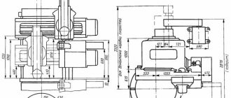
| Overall dimensions of the machine, mm | ||
| Length | mm | 2270 2520* 3020* |
| Width | mm | 1110 |
| height | mm | 1505 |
| Machine weight | kg | 2150 2270* 2540* |
Caliper | ||
| The greatest distance from the center axis to the edge of the tool holder | mm | 185 |
| Number of calipers | 1 | |
| Overload protection | available | |
| Blocking longitudinal and transverse feeds | available | |
| Maximum movement (by hand, along the lead shaft, along the lead screw): | ||
| longitudinal | mm | 750 1000* 1500* |
| transverse | mm | 220 |
| Bystrov moving | ||
| longitudinal | m/min | 5 |
| transverse | m/min | 2,5 |
| Move one division longitudinally: | ||
| on the limb | mm | 1 |
| by vernier | mm | 0,1 |
| Transverse movement of one dial division | mm | 0,025 |
| Limits of longitudinal feeds | mm/rev | 0,05…2,8 |
| Cross feed limits | mm/rev | 0,025…1,4 |
| Limits of pitches of cut threads: | ||
| metric | mm | 0,25…56 |
| inch | number of threads per 1″ | 112…0,5 |
| modular | modules | 0,25…56 |
| pitching | pitches | 112…0,5 |
| Moving one turn of the dial": | ||
| longitudinal | mm | 100 |
| transverse | mm | 5 |
Upper caliper | ||
| Maximum rotation angle | hail | ± 90 |
| The price of one division of the rotation scale | hail | 1 |
| Maximum displacement | mm | 120 |
| Price of one division | mm | 0,05 |
| Moving the dial one revolution | mm | 3 |
Spindle | ||
| Number of forward rotation speeds | 21 | |
| Number of reverse rotation speeds | 21 | |
| Spindle speed limits: | ||
| direct rotation | rpm | 20…2000 or 25…2500 |
| reverse rotation | rpm | 20…2000 or 25…2500 |
| Spindle flange diameter | mm | 170 |
| Spindle hole diameter | mm | 45 |
| Spindle braking | available | |
Tailstock | ||
| Center size in quills according to GOST 13214-79 | Morse taper 5 | |
| Maximum quill movement | mm | 120 |
| The price of one division of the quill movement scale: | ||
| rulers | mm | 5 |
| vernier | mm | 0,1 |
| Lateral movement | ||
| forward | mm | 5 |
| back | mm | 5 |
Machine drive | ||
| Electric motors: | ||
| Main movement: | ||
| power | kW | 7,5 |
| rotation frequency | rpm | 1500 |
| Accelerated motion drives: | ||
| power | kW | 0,37 |
| rotation frequency | rpm | 1500 |
| Cooling pump: | ||
| power | kW | 0,12 |
| rotation frequency | rpm | 3000 |
| innings | l/min | 22 |
| Lubrication station: | ||
| power | kW | 0,12 |
| rotation frequency | rpm | 1500 |
| innings | l/min | 3 |
| Grinding or sharpening attachment: | ||
| power | kW | 0,55 |
| rotation frequency | rpm | 3000 |
Note * - on special order.
Drawing - 16e16kp caliper sketch
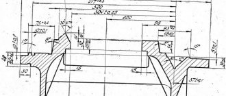
Drawing - 16e16kp sketch of the spindle
Modifications of the universal screw-cutting lathe 16E16KP
- 16G16 - normal accuracy with a recess in the bed
- 16L20 - normal accuracy, lightweight
- 16B16K - machine with automatic transmission
- 16G16K - a machine with a recess in the bed and an automatic transmission
- 16L20K - lightweight normal precision machine with automatic transmission
- 16M16 - normal precision mechanized machine with hydrocopier
- 16B16F3 - CNC lathe Kontur 2PT-71
- 16M16T1, SAMAT 135NC – chuck-centered CNC lathe
- 16B16P - high precision machine
- 16L20P - lightweight high-precision machine
- 16L20PF1 - high precision machine with digital display device
- 16B16KP - high precision machine with automatic transmission
- 16L20KP - lightweight high-precision machine with automatic transmission
- 1E16KP - high precision machine with automatic transmission
- 16B16P SV - high precision machine with stepless drive RMC = 750 mm
- 16B16P MV - high precision machine with stepless drive RMC = 1000 mm
- 16B16P LV - high precision machine with stepless drive RMC = 1500 mm
- 16B16T1, 16B16T1S1 - high precision CNC machine
- 16B16A - particularly high precision machine
- 16B16KA - particularly high precision machine with automatic transmission
- 16B16AB - particularly high precision machine for finishing turning operations
- 16B16S - ultra-high precision machine for finishing turning operations
- 16L20F1 - normal accuracy with digital display device
Modern analogues of the 16E16KP screw-cutting lathe
250ITPM.12 - Ø 320, manufacturer Izhevsk Machine Tool Plant. IzhStanko
16GS52SU - Ø 320, manufacturer Gomel Machine Unit Plant, RUP
16TV16 - Ø 325, manufacturer Astrakhan Machine Tool Plant
TV-380K - Ø 380, manufacturer Savelovsky Machine-Building Plant, JSC Savma, Kimry
1330 — Ø 330, manufacturer Jesco (Jessey) Taiwan
C6132 - Ø 320, manufactured by Shandong Weida Heavy Industries Co.,Ltd. China
CDS6132, CDS6232 - Ø 320, manufacturer Dalian Machine Tool Group DMTG, China
C0632A, C0632B, C6232A2, C6232B2, C0632B - Ø 330, manufacturer Zhejiang Kaida Machine Tool Co., Ltd, China
Samat 400S, Samat 400M, Samat 400L - Ø 400, manufacturer Srednevolzhsky machine-tool plant SVZS, Samara
16B20 - Ø 400, manufacturer Astrakhan Machine Tool Plant
MK605 - Ø 400, manufacturer Red Proletarian, Moscow
MST1620M - Ø 400, manufacturer Minsk Machine Tool Plant named after. October Revolution MZOR
KA-280 - Ø 400, manufacturer Kiev machine tool plant Verkon
ZHA-805 - Ø 400, manufacturer Zhitomir machine tool plant VerstatUniversalMash
16D20P - Ø 400, manufacturer: Alma-Ata Machine Tool Plant named after. 20th anniversary of October
CA6140A, CA6140B, CA6240A, CA6240B, - Ø 400, manufactured by Shenyang Machine Tool (Group) Co., Ltd. SMTCL China
CD6140A, CD6240A - Ø 400, manufacturer Dalian Machine Tool Group DMTG China
CS6140, CS6140A, CS6240, CS6240A, BJ1630G, BJ1630GD - Ø 400, manufactured by Bochi Machine Tool Group Co.,ltd. China
C6240 - Ø 400, manufacturer Anhui Chizhou Household Machine Tool China
CU400, CU400M, C400TM - Ø 440, manufacturer Zmm-Bulgaria Holding Ltd., ZMM Bulgaria Holding
CU402 - Ø 400, manufacturer ZMM Vratsa, ZMM Vratsa, Bulgaria
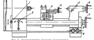
List of controls for screw-cutting lathe 16E16KP
- Plate with explanatory graphic symbols
- Handles for setting the feed rate and thread pitch
- Handles for setting the feed rate and thread pitch
- Emergency button
- Main drive motor activation button
- Normal or increased pitch activation handle
- Handle for changing cutting direction
- Plate with explanatory graphic symbols
- Switching handle
- Load indicator
- Signal lamp
- Handle for connecting the electrical equipment of the machine to the network
- Cooling pump activation handle
- Main drive motor speed shift handle
- Automatic transmission control handle
- Caliper cross feed handle
- Handle for turning and fastening the cutting head
- Screw securing the carriage to the frame
- Upper caliper feed handle
- Button for turning on the electric motor for rapid movements of the carriage and support
- Tailstock quill fastening handle
- Tailstock cross offset screw
- Handle for attaching the tailstock to the frame
- Tailstock quill movement flywheel
- Overdrive motor belt tension screw
- Handle for controlling the strokes of the carriage and caliper
- Lead screw nut engagement handle
- Nut for adjusting the apron release force against the stop
- Clutch activation handle for apron overload mechanism
- Plate with explanatory graphic symbols
- Handles for starting the machine and reversing the spindle
- Rack and pinion button
- Handwheel for manual carriage movement
- Plate with explanatory graphic symbols
- Handles for starting the machine and reversing the spindle
- Handles for setting the feed rate and thread pitch
- Gearbox control knob
- Headstock drive belt tension screw
- Main drive motor belt tension screw
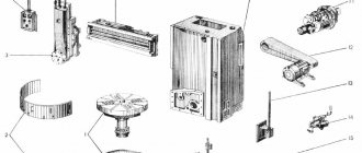
Location of the main components of the screw-cutting lathe 16E16KP
Location of the main components of the screw-cutting lathe 16E16KP
- Bed - 16B16P.011.000
- Cabinet - 16E16KP.017.000
- Spindle head - 16E16KP.021.000
- Automatic transmission - AKP 109-6.3
- Rear headstock - 16E16KP.330.000
- Caliper - 16E16KP.045.000
- Tool holder - 16E16KP.048.000
- Carriage - 16B16P.051.000
- Apron - 16B16P.062.000
- Feed box - 16B16P.070.000
- Gearbox (guitar) - 16B16P.080.000
- Rapid speed drive - 16E16KP.159.000
- Main drive pulleys - 16E16KP.168.000
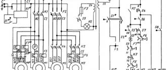
- Control cabinet - SHO 5906
- Lubrication system - 16E16KP.240.000
- Cooling - 16B16P.251.000
Kinematic diagram of a lathe model 16E16KP
Kinematic diagram of the machine 16E16KP
- A - AKS - automatic gearbox for machines 16B16K, 16B16KP, 16G16K
- a - spindle head
- b - tool holder
- in — caliper
- g - tailstock
- d - apron
- e - carriage
- g - gearbox for machines 16B16, 16B16P, 16G16
* for spindle speed 16..1600 rpm
** for spindle speed 25..2500 rpm
Tailstock of screw-cutting lathe 16E16KP
Tailstock of machine 16E16KP
Machine bed
The bed is a cast iron box-shaped frame with transverse U-shaped ribs - it has two prismatic and two flat guides. The guides are subjected to heat treatment followed by grinding. The bed is installed on one stand. In the niche of the right end of the frame there is an electric motor for rapid movements of the carriage.
A gearbox is mounted on the rear wall at the left end of the cabinet, a lubrication station is located at the right end, and the main drive electric motor is located inside the cabinet.
In the niche of the right end of the cabinet there is a coolant reservoir and a cooling system pump.
Gearbox
The six-speed gearbox (installed on machines 16E16KP, 16B16P, 16G16, 16L20F1, 16L20PF1, I6L20, 16L20P) is mounted in a separate housing and attached to the rear outer wall of the left end of the cabinet.
To tension the belt running from the box to the spindle, the box can be moved in a vertical plane using screw b (Fig. 5).
The gearbox mechanism is driven by a two-speed electric motor through a toothed belt drive.
Pulley 16, connected to the splined hub 15, transmits rotation to the shaft 14, which freely passes through the sleeve shaft 20.
Shaft 14 is connected to the disks of the drive electromagnetic clutch 25, when turned on, movement from shaft 14 is transmitted to the associated shaft-sleeve 20, through half-coupling 24. The gearbox allows you to obtain six different speeds on the output pulley 13. Next, the movement is transmitted through a toothed belt drive to spindle head pulley.
All gears 7-11, 18, 19, 22 gearboxes are made of alloy steel and subjected to heat treatment followed by grinding of the tooth profile.
Connected to the output shaft 4 of the gearbox is an electromagnetic brake clutch 3 with a lead screw 12, which ensures reliable and fast braking of the machine.
Lubrication of electromagnetic couplings, gears and gearbox bearings is carried out from the lubrication pump by watering through pipelines I, 43 with fittings 2, 44.
Speed shift mechanism on machines 16E16KP, 1616P, 16GI6, 16L20, 16L20P, 16L20F1, 16L20PF1
The spindle rotation speed is set using handles 9, 37 (see Fig. 3) and electric switch 14.
The gearbox control is single-handle.
When choosing one or another gearbox speed, handle 27 (see Fig. 5) must be tilted towards itself until it stops, then, turning it to the left or right, align pointer 29 with the required speed number. After this, handle 27 is sent forward.
The gearbox control mechanism has a built-in limit switch located on the upper wall of the gearbox housing, which, when the handle 27 is tilted toward itself, turns off the electric motor, drive 24 and brake 3 clutches. The inertial rotation of the gears of the gearbox makes it easy to engage them when changing gears.
The handle 27, when tilted toward itself through the pin 28, pulls the rod 37, which in turn turns the lever 31 sitting on the axis 32. The rack sector 30 slides along the teeth of the rack 5.
Lever 31, through axis 32, turns lever 33, which with its cracker fits into the groove of drum 23, which, moving along the axis, with its disk B presses on fingers 38 and through rods 40, forks 41 puts all the gears of the gearbox in a neutral position.
When the handle 27 is rotated to the left and to the right when choosing a particular speed, the gear sector 30 raises or lowers the rack 5 connected to the gear 22. The gear 22, associated with the fixing disk E and the locking disk A of the rods 40 through the axis 26, turns drum 23.
The angular fixation of the drum 23 and the handle 27 and the choice of speed is carried out by the roller of the spring-loaded lever 34, and the axial fixation is carried out by the ball 36.
Disk A for blocking the rods when turning the gear wheel 22 rotates freely in the slots of the bushings 39. On the disc A there is a number of millings, which, when a certain speed is selected, are located opposite the bushings of those rods 40, which at the moment will engage the required pair of gear wheels
Disc D of drum 23 has a number of projections and depressions.
When choosing a certain speed, the protrusions of the disk D are located against the fingers 38 of the rods 40.
By tilting the handle 27 away from you, we return the drum 23 in the same way, as described above, to its original position.
The depressions of the disk D pass the fingers 38 of the rods 40, and the two protrusions of the disk, resting on the fingers 38, move through the rods 40 and forks 41 the necessary pair of gears corresponding to the selected speed.
The milling of disk A allows bushings 39 of the moving rods to pass through. The remaining rods through bushings 39 are blocked by disk A from axial displacement.
Drum 23 in the working position is blocked from rotation by pin 42.
Thus, each of the rods receives a reciprocating motion depending on the position of the grooves of disk D of drum 23 and the grooves of the blocking disk A.
The forks connected to the rods move gears 9, II, 17, 19, 21 along the splined shafts in certain combinations.
The working fixed position of a pair of gears corresponding to the selected speed is as follows: in the axial direction, the gears are fixed through forks 41, rods 40, pins 38 between disks B and D of drum 23, and drum 23 by ball 36.
When installing the gear shift system, the following must be taken into account:
- rack 5 should protrude 61 mm above the upper plane of the gearbox housing. This will ensure proper operation of the gear shift mechanism;
- the gear 22 is brought into engagement with the rack 5 at the position of disk B corresponding to the first speed;
- in all six positions of drum 23, the correct operation of the switching system is checked.
Pins 38 and bushings 39 must pass freely through the corresponding milling slots in disks D and A.
This is achieved by turning the rods 40 relative to the shift forks 41 while loosening the latter.
To loosen the fastening of the forks 41, located on two rods at the rear wall of the gearbox, holes are provided, closed with exhaust plugs 35.
The gear sector 30 on the rod 37 must be installed so that during the reciprocating movement and rotation of the rod 37 it does not disengage with the rack 5.
In addition to the above, it must be borne in mind that when the belt is tensioned, the gearbox-spindle, gear sector 30 and lever 31 change their positions relative to the rack 5 and rod 37.
When tensioning the belt, it is necessary to make adjustments to the position of the elements by rotating sector 30 relative to rod 37 and changing lever 31 along axis 32.
Speed shift mechanism on machines 16B16K, 16E16KP, 16G16K, 16L20K, 16L20KP
The spindle rotation speed is set by handle 9 (see Fig. 3) and two handles 14 and 15.
The automatic transmission installed on the machines is controlled using handle 15 located on the electrical cabinet panel.
A description of the operation and design of the automatic transmission is given in the transmission manual.
Machine spindle head
The headstock mechanism receives movement from the gearbox through a toothed belt and a balanced take-up pulley 7 (Fig. 6) with seal 4.
Pulley 7 sits on the cone of the clutch-gear 5, rotating on two angular contact bearings 3 located in housing 6.
The axial play in the bearings is sampled using spring 4.
The machine spindle receives 12 rotation speeds directly from the receiving pulley through the gear clutch 5; 12 speeds with 1:4 shift through gears 5, 8, 16, 15; 12 speeds with 1:16 gearing through gears 5, 8, 11, 10, 13, 14, 16, 15.
Turning on the selector groups, gear clutch 12 or turning off the spindle for dividing into passes when cutting threads is carried out by handle 9 (see Fig. 3) using translations through a system of levers controlled by the curves of the cams.
Reliable fixation of the axis of the handle 9 from rotation in the working position is carried out by a spring-loaded ball located in a glass on the rear wall of the spindle head housing.
Spindle 17 (see Fig. 6) of the machine rotates on two tapered roller bearings 18 and 21.
The radial clearance in the bearings is selected using springs 20.
The machine spindle, which has a flanged front end, made in accordance with GOST 12593-72, ensures quick change of the faceplate and its reliable fastening.
The headstock mechanism allows:
- cut threads with an increased pitch of 4 and 16 times;
- cut right-hand and left-hand threads;
- cut multi-start threads when working with cuts 1:4 and 1:16 with the number of starts 2, 3, 4, 5, 6, 10, 12, 15, 20, 30, and when working directly with the number of starts 2, 3, 4 , 6, 12.
Transmissions are carried out by gears 1, 2, 22, 23, 24 and the wheels listed above.
Machine gearbox
The gearbox is shown in Fig. 7 and serves to transmit motion from the headstock output shaft to the feedbox drive shaft.
To obtain feed and cut metric and inch threads, gear wheels of the main set are installed with a gear ratio of 40/73 73/64, and for cutting modular and pitch threads - with a gear ratio of 60/73 * 86/36
The gearbox guard is equipped with an electrical lock, which prevents accidental activation of the machine when the guard casing is open.
Gearbox
The feed box consists of gears 1-14, 16-23 and receives movement from the headstock output shaft through replaceable gearbox gears.
The required feeds and thread pitches were set by turning handles 3 and 36 (see Fig. 3) located on the front cover of the feed box.
Turning on the lead screw or lead shaft, selecting the type of thread is done with handle 2.
The direction of rotation of the lead screw is changed by turning handle 7, normal or increased thread pitch is set by handle 6.
To cut more precise threads in the feed box, handle 2 is provided in a position in which the lead screw is engaged directly, bypassing the feed box mechanism. In this case, the required pitch is selected by interchangeable gear wheels of a special set.
To carry out rapid movements of the caliper, an overrunning clutch 15 is mounted in the feed box (see Fig. 8), the purpose of which is to turn off the feed box during the rapid return stroke of the caliper.
The mechanism for switching gears of the feed box is assembled on one plate 26, which is attached to the feed box body. The gears are switched using a system of levers, rods and cams. Fixation of the working position of the gears is ensured by spring-loaded balls located in the shift handles.
When dismantling the switching mechanism, it is necessary to ensure the correct installation of gear wheels 24 and 2.5, which have risks that must coincide during installation, otherwise the order of engagement of the gear wheels of the feed box will be disrupted.
Apron
The apron has four pairs of cam clutches I (Fig. 9), 2, 3, 4, which allow forward and reverse strokes of the carriage and support. The movements of the carriage and the lower part of the support are controlled by handle 19. The direction in which the handle is turned on coincides with the direction of movement of the carriage and support.
The inclusion of rapid movements of the caliper in the indicated four directions is carried out by additionally pressing the IB button built into the handle 19.
At the same time, the high-speed electric motor is turned on, which, through a V-belt transmission, communicates movement to the running shaft.
The amount of movement of the apron using the flywheel is counted along the dial and vernier with a division value of I and 0.1 mm, respectively.
The apron has a blocking device that prevents the simultaneous activation of the longitudinal and transverse feeds of the support and the machine's uterine nut.
The apron has a built-in safety mechanism against machine overload, adjusted to the maximum apron release force (6000 ± 500) H.
When working along the stops, the apron disconnection force can be reduced to the required value by using nut 6 and loosening spring 7.
The safety mechanism works as follows.
When the carriage meets the stop or when the worm gear 14 is overloaded and, therefore, stops, the worm 13, continuing to rotate, turns out and through the cracker 12, pusher II, thrust bearing 10, compressing the spring 7, pushes the cup 9 to the right.
The latch 8, falling into the slot of the glass 9, prevents the worm from returning to its original position.
With further rotation of the worm, the coupling 15 shifts to the right under the influence of the spring 15, the fine-toothed part of the coupling 15 disengages with the coupling 17. The worm 13 begins to rotate.
To turn on the apron, you need to release the glass 9 by lifting the latch 8.
Spring 7 will turn on the disengaged gear couplings 15. 17 and the worm 13.
To cut a thread, you need to set handle 19 to the neutral position and use handle 20 to turn on the nut. In this case, the rack and pinion gear should be disengaged by pulling button 5 towards you.
The apron, bed guides and carriage are lubricated by a plunger pump built into the apron cover.
Machine support
The tool holder, with the help of a support, can move along and across the bed from a mechanical drive at working feed and accelerated, as well as by hand.
The carriage and transverse slider of the caliper have travel restrictions in both directions. When the caliper is moved all the way, the apron disconnect mechanism is activated.
If necessary, the support carriage (Fig. 11) can be secured anywhere on the frame using screw 18 (see Fig. 3).
Tailstock
The tailstock is attached to the frame through a system of levers and an eccentric handle I (Fig. 12).
If necessary, the transverse displacement of the body is carried out by screws 10, 12 with the handle clamp I in the released position.
Control of the correct position of the tailstock body is carried out roughly by the places pressed during assembly and precisely by the mandrel clamped in the centers of the machine.
In this case, the discrepancy between the axis of rotation of the spindle and the axis of the quill hole in the horizontal plane should not exceed 0.01 mm.
The flat end of screw 4 slides in the fixing groove of eccentric 3. To unscrew screw 4 to dismantle eccentric 3, it is necessary to align the counterbore A with screw 4.
The quill 8 is clamped by handle 7.
ATTENTION! MAXIMUM quill STROKE – 120 mm. Screw 9 moves from handwheel 2.
Chip protection device
The chip protection device consists of a support guard and a machine guard.
The support guard, which has a folding transparent screen, is mounted on the carriage and moves with it.
The height of the screen can be adjusted.
The purpose of the machine guard, which consists (mainly) of a shield suspended from the back of the support, is to protect the space surrounding the machine from flying chips.
Stop for limiting the longitudinal movement of the carriage
The stop for limiting the longitudinal movement of the carriage is installed on the front shelf of the frame, secured with screws and a clamping bar and equipped with a fine adjustment screw having a vernier with a division value of 0.05 mm.
Description of the main components of the screw-cutting lathe 16E16KP
Machine bed
The bed is a cast iron box-shaped frame with transverse U-shaped ribs - it has two prismatic and two flat guides. The guides are subjected to heat treatment followed by grinding. The bed is installed on one stand. In the niche of the right end of the frame there is an electric motor for rapid movements of the carriage.
A gearbox is mounted on the rear wall at the left end of the cabinet, a lubrication station is located at the right end, and the main drive electric motor is located inside the cabinet.
In the niche of the right end of the cabinet there is a coolant reservoir and a cooling system pump.
Automatic gearbox of machine 16E16KP
Automatic gearbox AKP 109-6.3
9 steps is mounted in a separate housing and attached to the rear outer wall of the left end of the cabinet.
To tension the belt running from the box to the spindle, the box can be moved in a vertical plane using a screw.
The gearbox mechanism is driven by an electric motor through a toothed belt drive.
Lubrication of electromagnetic couplings, gears and gearbox bearings is carried out from the lubrication pump by watering through pipelines I, 43 with fittings 2, 44.
Speed shift mechanism on the 16E16KP machine
Control of automatic transmission AKP 109-6.3
installed on the machines, is done using handle 15 located on the electrical cabinet panel.
A description of the operation and design of the automatic transmission is given in the transmission manual.
Technical characteristics of the Automatic gearbox AKP 109-6.3
- Rated load torque on the output shaft - 138 N.m
- Output shaft rotation speed limits - 400..2500 rpm
- Rated input shaft speed: 1600 rpm
- Number of direct passes - 9
- Number of return transfers - no
- Output shaft speed range coefficient - 1.26
- Drive motor power - 7.1 kW
- Acceleration time - 2.5 s
- Braking time 2.0 s
- Voltage of power supply circuits of electric couplings - 24 V
- Weight - 140 kg
Machine spindle head
Drawing of the spindle head of the screw-cutting lathe 16E16KP
The headstock mechanism receives movement from the gearbox through a toothed belt and a balanced take-up pulley 7 (Fig. 6) with seal 4.
Pulley 7 sits on the cone of the clutch-gear 5, rotating on two angular contact bearings 3 located in housing 6.
The axial play in the bearings is sampled using spring 4.
spindle 16e16kp receives 21 rotation speeds from 20 to 2000 rpm;
- 9 speeds directly 1:1 from the gearbox, take-up pulley through clutch-gear 5;
- 9 speeds with 1:4 overdrive through overdrive gears 5, 8, 16, 15;
- 9 speeds with 1:16 overdrive through gears 5, 8, 11, 10, 13, 14, 16, 15.
Thus, the spindle receives 27 speed steps (9 x 3 = 27), of which 6 values are repeated.
Turning on the selector groups, gear clutch 12 or turning off the spindle for dividing into passes when cutting threads is carried out by handle 9 (see Fig. 3) using translations through a system of levers controlled by the curves of the cams.
Reliable fixation of the axis of the handle 9 from rotation in the working position is carried out by a spring-loaded ball located in a glass on the rear wall of the spindle head housing.
Spindle 17 (see Fig. 6) of the machine rotates on two tapered roller bearings 18 and 21.
The radial clearance in the bearings is selected using springs 20.
The machine spindle, which has a flanged front end, made in accordance with GOST 12593-72, ensures quick change of the faceplate and its reliable fastening.
The headstock mechanism allows:
- cut threads with an increased pitch of 4 and 16 times;
- cut right-hand and left-hand threads;
- cut multi-start threads when working with cuts 1:4 and 1:16 with the number of starts 2, 3, 4, 5, 6, 10, 12, 15, 20, 30, and when working directly with the number of starts 2, 3, 4 , 6, 12.
Transmissions are carried out by gears 1, 2, 22, 23, 24 and the wheels listed above.
Machine gearbox (guitar)
The gearbox is shown in Fig. 7 and serves to transmit motion from the headstock output shaft to the feedbox drive shaft.
To obtain feed and cut metric and inch threads, gear wheels of the main set are installed with a gear ratio of 40/73 73/64, and for cutting modular and pitch threads - with a gear ratio of 60/73 * 86/36
The gearbox guard is equipped with an electrical lock, which prevents accidental activation of the machine when the guard casing is open.
Gearbox
The machine's feed box provides feeds for turning, as well as cutting metric, inch, modular and pitch threads.
The feed box consists of gears 1-14, 16-23 and receives movement from the headstock output shaft through replaceable gearbox gears.
The required feeds and thread pitches were set by turning handles 3 and 36 (see Fig. 3) located on the front cover of the feed box.
Turning on the lead screw or lead shaft, selecting the type of thread is done with handle 2.
The direction of rotation of the lead screw is changed by turning handle 7, normal or increased thread pitch is set by handle 6.
To cut more precise threads in the feed box, handle 2 is provided in a position in which the lead screw is engaged directly, bypassing the feed box mechanism. In this case, the required pitch is selected by interchangeable gear wheels of a special set.
To carry out rapid movements of the caliper, an overrunning clutch 15 is mounted in the feed box (see Fig. 8), the purpose of which is to turn off the feed box during the rapid return stroke of the caliper.
The mechanism for switching gears of the feed box is assembled on one plate 26, which is attached to the feed box body. The gears are switched using a system of levers, rods and cams. Fixation of the working position of the gears is ensured by spring-loaded balls located in the shift handles.
When dismantling the switching mechanism, it is necessary to ensure the correct installation of gear wheels 24 and 2.5, which have risks that must coincide during installation, otherwise the order of engagement of the gear wheels of the feed box will be disrupted.
Apron
Drawing of the Apron of the screw-cutting lathe 16E16KP
Drawing of the Apron of the screw-cutting lathe 16E16KP
The machine apron ensures the movement of the support carriage.
The apron has four pairs of cam clutches I (Fig. 9), 2, 3, 4, which allow forward and reverse strokes of the carriage and support. The movements of the carriage and the lower part of the support are controlled by handle 19. The direction in which the handle is turned on coincides with the direction of movement of the carriage and support.
The inclusion of rapid movements of the caliper in the indicated four directions is carried out by additionally pressing the IB button built into the handle 19.
At the same time, the high-speed electric motor is turned on, which, through a V-belt transmission, communicates movement to the running shaft.
The amount of movement of the apron using the flywheel is counted along the dial and vernier with a division value of 1 and 0.1 mm, respectively.
The apron has a blocking device that prevents the simultaneous activation of the longitudinal and transverse feeds of the support and the machine's uterine nut.
The apron has a built-in safety mechanism against machine overload, adjusted to the maximum apron release force (6000 ± 500) H.
When working along the stops, the apron disconnection force can be reduced to the required value by using nut 6 and loosening spring 7.
The safety mechanism works as follows.
When the carriage meets the stop or when the worm gear 14 is overloaded and, therefore, stops, the worm 13, continuing to rotate, turns out and through the cracker 12, pusher II, thrust bearing 10, compressing the spring 7, pushes the cup 9 to the right.
The latch 8, falling into the slot of the glass 9, prevents the worm from returning to its original position.
With further rotation of the worm, the coupling 15 shifts to the right under the influence of the spring 15, the fine-toothed part of the coupling 15 disengages with the coupling 17. The worm 13 begins to rotate.
To turn on the apron, you need to release the glass 9 by lifting the latch 8.
Spring 7 will turn on the disengaged gear couplings 15. 17 and the worm 13.
To cut a thread, you need to set handle 19 to the neutral position and use handle 20 to turn on the nut. In this case, the rack and pinion gear should be disengaged by pulling button 5 towards you.
The apron, bed guides and carriage are lubricated by a plunger pump built into the apron cover.
Machine support
Drawing of a support for a screw-cutting lathe 16E16KP
The tool holder, with the help of a support, can move along and across the bed from a mechanical drive at working feed and accelerated, as well as by hand.
The carriage and transverse slider of the caliper have travel restrictions in both directions. When the caliper is moved all the way, the apron disconnect mechanism is activated.
If necessary, the support carriage (Fig. 11) can be secured anywhere on the frame using screw 18 (see Fig. 3).
Tailstock
Drawing of the tailstock of a screw-cutting lathe 16E16KP
The tailstock is attached to the frame through a system of levers and an eccentric handle I (Fig. 12).
If necessary, the transverse displacement of the body is carried out by screws 10, 12 with the handle clamp I in the released position.
Control of the correct position of the tailstock body is carried out roughly by the places pressed during assembly and precisely by the mandrel clamped in the centers of the machine.
In this case, the discrepancy between the axis of rotation of the spindle and the axis of the quill hole in the horizontal plane should not exceed 0.01 mm.
The flat end of screw 4 slides in the fixing groove of eccentric 3. To unscrew screw 4 to dismantle eccentric 3, it is necessary to align the counterbore A with screw 4.
The quill 8 is clamped by handle 7.
ATTENTION! MAXIMUM quill STROKE – 120 mm. Screw 9 moves from handwheel 2.
Chip protection device
The chip protection device consists of a support guard and a machine guard.
The support guard, which has a folding transparent screen, is mounted on the carriage and moves with it.
The height of the screen can be adjusted.
The purpose of the machine guard, which consists (mainly) of a shield suspended from the back of the support, is to protect the space surrounding the machine from flying chips.
Stop for limiting the longitudinal movement of the carriage
The stop for limiting the longitudinal movement of the carriage is installed on the front shelf of the frame, secured with screws and a clamping bar and equipped with a fine adjustment screw having a vernier with a division value of 0.05 mm.