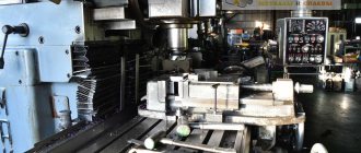
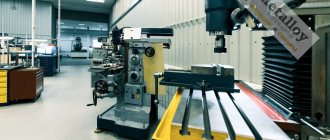
Milling machines include a large group of metal-cutting equipment. It is distinguished by the rotational movement of a multi-blade cutting tool mounted on a spindle and the translational movement of the part relative to the cutter.
Various types of tables and devices allow for boring, processing cylindrical surfaces, cutting teeth, and making complex reliefs with great accuracy.
What can you do with it, and what is it for?
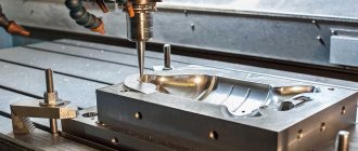
The main purpose of a milling machine is to process flat surfaces with high speed and cleanliness. A milling cutter is a multi-bladed tool that rotates and immediately cuts a wide strip of metal from the workpiece.
Boring heads, centers, rotary and inclined tables increase the capabilities of milling machines. They perform many operations, including:
- milling of horizontal and lateral planes;
- creation of complex terrain;
- cutting grooves;
- drilling and boring;
- trim;
- processing of curly edges;
- cutting straight and oblique teeth on gears;
- creation of helical grooves;
- processing around the perimeter of parts of complex shapes.
A milling machine can quickly produce slats, cushions, levers, cranks and other parts with a flat surface and holes.
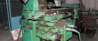
Main components, device and principle of operation
A milling machine processes a workpiece fixedly fixed on a table with a rotating multi-bladed tool. The movement of the part relative to the cutter occurs due to the movement of the table and slide in the transverse and longitudinal direction. The console or spindle head can move vertically.
Base
At the bottom of the machine there is a base. This is usually cast iron platinum. Some models of horizontal milling machines have a high, hollow lower part. It may contain electrical components and a starting panel. Through holes in the base, the machine is attached to the floor with anchors.
bed
Cast hollow part with increased strength. It provides rigidity to the machine and dampens vibrations. The console and trunk move along the guides of the frame. For single-rack models, the gearbox and electrical cabinet are located inside, and the main drive electric motor is installed below.
For non-cantilever equipment processing large parts, the frame is installed on a special concrete base. It is long, with guides for moving the table from above. On the side, along the entire length, there is a screw for the longitudinal movement of the racks - the portal. Electrical cabinets are located nearby.
Trunk
Assembly of a horizontal milling machine. It moves along guides located at the top of the rack parallel to the axis of rotation of the spindle. An earring moves along it, holding the free end of the mandrel with a disk cutter. Mechanical movement is provided by its own drive. The electric motor is mounted on the trunk at the rear.
Reference! Only square trunks installed on top have mechanical movement. The older ones are round and can only be pulled out manually.
Console
A complex assembly located at the front of the milling equipment. It is lifted vertically by a rotating shaft fixed to the base of the machine. The chassis slides along rails at the front of the rack. Inside the console there is a gearbox powered by a flange motor installed here. There are slides on the transverse guides of the console. A table moves along them in the longitudinal direction. The console is equipped with flywheels and control handles for feeding the table movement and adjusting the speed.
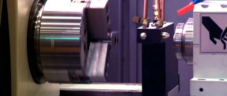
Spindle
The spindle assembly is located in the upper part of the rack and is connected by gearing to the gearbox. It has several speeds 6–18, which are activated by moving the gears in the gearbox. The spindle only rotates around its axis at high speed. Longitudinal movement is available on some models, it is small, up to 75 mm. A cone and collets are used to secure the tool.
Electric motors
Console models have 3 electric motors:
- main movement drive;
- innings;
- coolant pump
Desktop models have 3 stepper motors for movement in each axis. There is a separate drive on the spindle. Large gantry equipment has several motors: table movements and on each spindle unit.
Gearbox
Consists of several shafts with gears. When switching gear pairs, the rotation speed on the output shaft changes. It is located in the upper part of the rack, next to the spindle and transmits movement to it through gearing. It is connected to the engine by an elastic coupling.
Gearbox
The feed box installed in the console transmits rotation from the electric motor to the slide, table and console. Switched by a round handle at the front of the machine.
Selection options
When choosing a milling machine, you should consider the most important characteristics of the device:
– a parameter that affects the processing speed of parts. It must be combined with the length and diameter of the cutter, as well as the service life of the tool. There are light models, medium or heavy units. With increasing power, all engine characteristics and the weight of the milling cutter increase.
Power- Working stroke – the maximum depth of immersion of the equipment into the material being processed. Household devices have an interval of 20 to 50 mm.
- The speed of rotation is an indicator that determines the productivity of using a tool. It is determined by the number of spindle rotations per minute. The equipment is selected in accordance with the physical and mechanical characteristics of the material being processed.
Expert opinion
Levin Dmitry Konstantinovich
For better processing and safety of the tool, it is better to select a groove of the required depth in several passes.
Additional functions help increase the efficiency and ease of use of the device:
- Constant electronics – controls the motor, supports and stabilizes the spindle movement. Usually installed on professional models of machines and improves the quality of finishing of parts.
- Smooth start – promotes a gradual increase in speed, without jerking, increasing the safety of using the machine.
- Overload protection – starts when the motor winding is critically heated. Triggering of the system in some models leads to a complete shutdown of the device, while in others it only activates the indicator light.
- Accidental start protection is a feature found in many types of milling machines. Integrated as a special button to lock the trigger.
The design elements of the machine also deserve attention:
- The sole is an important part, made of cast or stamped metal. The build quality of the platform determines the class of the unit. Stamped elements are found in budget models for household needs; they are covered with a special cover.
- Rod mechanism – provides vertical movement of the cutter.
- The size of the opening in the platform . The size of the attachment point determines the diameter of the equipment used. The set of cutters depends on the model of the machine.
Auxiliary elements
To facilitate high-precision processing, a structure in the form of a stop is used, fixed by steel crossbars on the side of the base. This device ensures uniform guidance of the cutter at a given distance from the edge. The rigid structure is separated from the workpiece by a plastic pad.
The guide rail helps when performing straight-line milling. Additional design elements simplify complex operations. The tire is attached at an angle to the workpiece or on the edge of the table top.
This part makes it possible to create holes at equal intervals, which is especially important when making furniture.
The ruler-compass helps to round off the workpieces. One end of it is attached to the base of the tool, and the other is inserted into the hole at the center of gravity.
To maintain cleanliness in the workplace, it is also convenient to use a vacuum cleaner that is combined with the unit using a pipe.
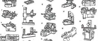
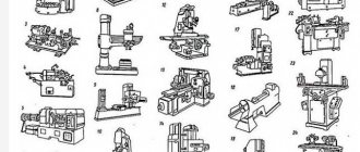
Classification and decoding of group markings
The group of milling machines is marked with the number “6”. Separately, 5 denotes gear hobbing equipment. There can be a letter after 6. It indicates which generation this model belongs to:
- up to 1932 inclusive there is no letter marking of the age of the equipment;
- B – 1932–1937
- K from 1937 to 1969
- N – 1951
- M – 1961
Since 1987, the marking has been marked with D.
The second or next number after the letter indicates the type of machine:
- 1 – vertical milling console type;
- 2 – continuous action;
- 4 – copying and engraving;
- 5 – vertical;
- 6 – longitudinal;
- 7 – widely-universal console;
- 8 – horizontal.
Below the number (all models that are not included in any group are collected. 3 remains free.
The type of machine is marked with its standard size. It is determined by the table. Its dimensions are normalized, for example:
- 0 – 200×800 mm;
- 1 – 250×1000 mm;
- 4 – 500×2000 mm.
The letter Ш at the end of the marking denotes widely universal machines. The accuracy class is indicated after the table size with the letters N, P.
Reference! Specialized machines produced by factories are marked with letters indicating the manufacturer’s designation. For example, the Gorky Milling Machine Plant puts GF and the machine number, DF means that the unit was created at the Dmitrov Milling Machine Plant.
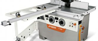
Best models
Currently in Russia there are few manufacturers producing high-quality universal milling equipment. Reliable domestic serial models can be called 6DM80Sh, 6T82Sh, 6M82Sh. Among the models produced in the near abroad, we note the widely-universal cantilever-milling FU350MRApUG-03, Republic of Belarus.
Among foreign manufacturers, universal milling machines of the MUF series, manufactured by STALEX, are known; BF500DDRO, Holzmann (Austria); VISPROM FHX-55PD, PROMA (Czech Republic). Universal milling cutters from Korean manufacturers are very reliable and in demand.
How much does it cost and what does the price depend on?
The cost of equipment depends on its type, power, level of mechanization and automation, “age”, condition, dimensions and weight of the workpieces processed, and manufacturer. A simple desktop machine with manual control from the Middle Kingdom can be found at a price within 1000 rubles. For old equipment of the 6M12P type, depending on the condition and region, they ask from 13,000 to 20,000 rubles.
CNC machines are an order of magnitude higher than their mechanically controlled counterparts. For example, a desktop milling and engraving machine will cost the buyer 6,000-8,000 rubles, for metal with water cooling from 30,000 rubles. The cost of high-performance industrial equipment for metal starts from 900,000 rubles.
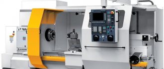
Operating principle of milling machines
Almost all milling machines operate on the same principle. The only differences can be in their functionality.
Basic elements of a milling machine
The main structural elements of such machines are: a supporting frame, a work table, clamping elements, a collet and a collet chuck in which the working tool is fixed, a portal with a spindle fixed to it, which can move, and a drive electric motor.
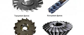
The working tool of any milling machine is a cutter, the design and dimensions of which depend on the configuration of the part to be processed. The working tool is fixed in the collet chuck using a shank, and rotation is transmitted to it from the drive electric motor through a gear system. The main purpose of the cutter is to remove an excess layer of metal from the workpiece, which, in fact, is the essence of processing on such a machine.
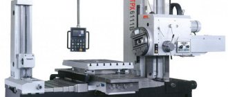
The machine spindle is placed on a movable portal, the movements of which are controlled by special controllers in the case of CNC equipment. The electronic system of such equipment includes CNC (computer numerical control) controllers, auxiliary system elements and connecting parts. The operating principle of CNC machine models is as follows: a special program reads the drawings of the part that needs to be obtained as a result of processing, generates electronic commands that are transmitted to the working part of the machine.
Widely universal machines, which are a hybrid of horizontal and vertical models, deserve special attention. Their design also includes a collet, collet chuck and clamps, but the gearbox of such machines transmits all movements from a single electric motor. Their distinctive feature is the presence of a manual mode, with which you can control the operation of the running unit.
Example of a kinematic diagram (cantilever milling machine)
Additional elements include a five-axis metal milling machine and engraving equipment. Such equipment is equipped with additional clamping elements that allow you to install an engraver on it. The tool of such equipment rotates due to the cardan shaft, with which it is directly connected to the electric motor.
The simplest in design are manual metal milling machines. Such equipment has low power, and its design consists of a collet with a collet chuck, a rotor, a drive head and an electric motor. Naturally, the functionality of such a machine is also limited: it can be used to perform only the simplest milling operations.
The service life of a manual milling group machine is also low and amounts to no more than 10,000 hours. The weakest components in such equipment, which are the first to fail, are the collet and collet chuck, clamps, attachment and spindle. But its low reliability and durability are fully compensated by its low cost. It makes sense to purchase it if you plan to use it irregularly.
How to install
Tabletop machines are unpacked, assembled and placed on a level surface. Connect to the network and the hood - vacuum cleaner. The base can easily withstand the light weight of workpieces and processing loads. Horizontally and vertically milling machines are installed on the concrete floor. The pouring thickness must be more than 300 mm.
Additionally, they are secured with bolts or studs so that they do not move due to vibration. If the floor does not match, dig a hole 500 mm deep. Sand is poured onto the bottom. Gravel on top. The thickness of the pillow is 200 mm. Then the cement mortar is poured and leveled.
Important!
For stable operation, equipment weighing more than a ton is recommended to be placed on hydraulic supports.
Caring for a hand-held milling device
Consists of timely fixation, mini adjustment of speed and depth of milling
Rotation speed adjustment
During operation of a hand router, it is necessary to adjust the rotation speed of the cutting mechanism. You need to start by reading the manual supplied by the manufacturer. If the document indicates a maximum value of 24,000 rpm, and the dial has 6 divisions, then each 1 division is equal to 4,000 rpm. The speed changes when you turn the dial.
Fixing the cutter
To fix the cutters, special-purpose chucks are used, equipped with an internal bolt, which must be screwed into the end part of the cutter.
Milling depth adjustment
At the next stage, the immersion depth is adjusted using a vertical stop with several adjustment stages. Loosen the clamps that secure the stop and the “head” of the router, lower the head until the cutter touches the plane (can be adjusted without the part).
Attention novice milling operators! To avoid injury, the router can only be moved in the opposite direction relative to the movement of the cutting head.
The movable stop is clamped and the pointer is installed at the point on the measuring scale corresponding to the zero division. The calibrated ruler is brought into a state of readiness for operating mode.
Features of configuration depending on the purpose
Before starting work, the machine is set up. At idle, the operation of all nodes and their execution of commands from the control panel are checked. Then the spindle runout is checked. All necessary equipment, fasteners, and tools are prepared. After installing the part, it must be secured. Check the correct position of the workpiece with an indicator. Install the table travel limit stops. Set the spindle speed, feed and depth of cut. Enable up or down milling, depending on the hardness of the material being processed.
What does the passport contain?
The passport for the milling machine contains:
- General information.
- Photos showing the main components and controls.
- Specifications.
- Contents of delivery.
- Security measures.
- Composition of the unit.
- Device.
- Electrical equipment.
- Lubrication system.
- Procedure for transportation and installation.
The passport describes the procedure for operating the equipment, its setup and typical malfunctions. There are diagrams of the main components. Milling machines are in demand in production and in the home workshop. Tabletop ones will help you make beautiful things for your home. Copy-milling machines will decorate furniture facades and panels with patterns.
Small floor-mounted machines with a table of 250×1000 mm are useful for the manufacture of spare parts for a car and the manufacture of simple mechanisms and devices. CNC machines can quickly and independently produce a part of any complexity without a program and repeat the cycle any number of times. They will come in handy in production.