What do you need to know to assemble a homemade welder?
To make a mini welding machine with your own hands from available materials, without special financial costs and effort, you need to understand how the equipment functions, after which you can start producing it at home.
First of all, it is worth determining the required power supply for homemade welding equipment. Connecting parts of a massive structure requires a higher current intensity, and welding work with thin metal surfaces requires minimal current.
The current value is related to the selected electrodes that will be used in the process. When welding products up to 5 millimeters, it is necessary to use rods up to 4 millimeters, and in a structure with 2 millimeters thick, rods should be 1.5 millimeters.
When using electrodes of 4 millimeters, the current is regulated up to 200 amperes, for 3 millimeters up to 140 amperes, for 2 millimeters - up to 70 amperes, and for the smallest ones up to 1.5 millimeters - up to 40 amperes.
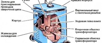
You can form an arc for the welding process yourself using the mains voltage, which is obtained through the operation of a transformer.
This equipment includes:
- magnetic circuit;
- winding – primary and secondary.
You can make the transformer yourself. For the magnetic circuit, plates made of steel or other durable material are used. Windings are necessary to directly perform welding work and to be able to connect the welding unit to a 220 volt network.
Specialized equipment has additional devices that improve the quality and power of the arc, which makes it possible to independently regulate the current values.
For welding equipment made at home, it is not necessary to use additional devices. Looking at the value of the current, you can select the power of the transformer, and to calculate the power, you need to multiply the current indicator that is used during operation of the equipment by 25.
The result obtained is multiplied by 0.015, where the result is the required value of the magnetic core diameter. To calculate the required winding cross-section, it is enough to divide the power by 2000, and then multiply the resulting number by 1.13.
To calculate how many turns of wiring need to be wound, you need to divide the cross-sectional area of the magnetic circuit in half.
If you are planning to make a simple welding machine with your own hands, then it should be noted that the welding process itself comes in several types - soft and hard, this is influenced by the voltage that is on the equipment clamp.
Using this parameter, you can set the properties of the external current for the welding process, which is also divided into flat, steep and increasing.
Most experts recommend using current sources with flat or steep characteristics. They have a minimal change in current when the electric arc oscillates, which makes it possible to weld metal at home.
How to make a welding unit with your own hands?
After studying the main features of the assembly process, you can proceed directly to assembling homemade equipment.
Today, there are a large number of different methods and recommendations on how best to assemble a homemade welding machine of any kind - with alternating or direct current, pulsed or inverter, automatic or semi-automatic.
There is no need to go deep enough into this topic, since one of the easiest ways to assemble a welding machine with your own hands is to use a transformer.
Its peculiarity is that it works with alternating current, which ensures the creation of a high-quality seam when welding metal surfaces. Such equipment can cope with any household work where it is necessary to weld metal or steel structures
To make it you need to prepare:
- Several meters of cable with great thickness.
- Material for the core that will be located in the transformer. The material itself must have increased permeability with magnetization.
The best option is when the rod-shaped core has the letter “P”. In some cases, it is allowed to use this part in a more modified form, for example, a round stator made from a damaged electric motor.
However, it is worth paying attention that it is more difficult to wind windings onto this shape. It is best when the core cross-section for classic welding equipment, made by hand and used for domestic purposes, had an area of about 50 cm2.
In order for the equipment to have an accessible weight, it is not necessary to increase the cross-section in volume, however, the technical effect will not be at the highest level. If the cross-sectional area does not suit you, then you can calculate it yourself using special diagrams and formulas.
The primary winding must be made of copper wire, which will have increased characteristics: thermal resistance, since during operation of the structure this part heats up very much.
Such a part must have cotton or fiberglass insulation. As a last resort, it is possible to use rubber insulated wire or rubber cloth, but beware of PVC winding.
The insulation is also made by hand, using cotton or fiberglass, or rather parts of it 2 cm wide. Thanks to these pieces, you can wrap the wire and then impregnate it with any varnish for electrical purposes. This insulation will not overheat after regular use.
Similar to the above calculations, it will be possible to calculate which cross-sectional area of the winding - primary and secondary - will be the most optimal. Often the secondary winding has an area of about 30 mm2, and the primary winding up to 7 mm2, using a rod of 4 millimeters in diameter.
In addition, in a simple way you need to determine how far a piece of copper wire will stretch and how many turns will be needed to wind two windings. After this, the coils are wound, and the frame is made using the geometric parameters of the magnetic core.
The main thing is to ensure that there are no difficulties when putting on the magnetic core. First of all, you need to choose the correct core size. It is best made using electrical cardboard or textolite.
Using the same analogue, it will be possible to make a structure for welding small parts. For home use, you can use a small mini welding machine.
How to make a welding generator with your own hands
A homemade welding generator is very convenient in places where there is no centralized power supply. To create such a device, basic knowledge in the field of electrical engineering and electromechanics is required. It should be taken into account that assembling the engine itself in makeshift conditions is practically impossible; then, when talking about how to make a generator, we mean the use and installation of ready-made components, mechanisms and materials.
Operating principle of a welding generator.
The welding generator includes several key components:
- Transformer.
You can wind it yourself, if you have transformer iron and copper wire with a suitable cross-section. All necessary indicators (cross-sectional area, as well as wire diameters) are calculated based on the planned power of the generator. The maximum diameter of the welding electrodes used depends on these indicators.
- Rectifier.
Visually, this is a bridge of fairly powerful diodes. The power level is calculated based on the amount of current planned for the welding transformer. So, if you plan to use five-millimeter welding electrodes, the welding current can reach up to 150-200V. The rectifier is installed on a heat-resistant fiberglass plate (you can also use getinax). During operation, powerful valves become hot.
- Current regulator.
This is a stepped or smooth rheostat, the main function of which is to change the current value in order to ensure optimal welding mode.
There are several schemes of welding generators. Two are especially popular.
- The series winding provides demagnetization, while the field winding remains independent. Power is supplied through a rectifier. Using the resulting magnetic flux, voltage is induced on the generator, followed by initiation of the arc. By switching the number of turns of the series winding, the welding current can be adjusted to the optimal value.
- Demagnetization occurs through the series winding. The excitation winding runs in parallel. In the manufacture of such generators, ferromagnetic steel will be needed; the magnetic poles contain residual magnetism. The power source can be an engine, both gasoline and diesel.
Making a homemade generator
Making a generator is quite simple. To do this, you need a separate room, for example, a garage.
First of all, you need to make a frame. Here you will need a metal corner 40*40mm. We measure the required length and cut the corners with a grinder. Next, holes are drilled for the generator and motor. The units are attached to the frame using bolts. To prevent the nuts from loosening, washers are placed under them.
For more convenient movement of the generator, wheels are installed on the frame. They are secured by welding; you can also make additional holes in the frame and use mounting bolts. The motor transmits torque to the generator. The rotation of the armature initiates the generation of electric current.
A similar circuit underlies all welding generators.
The welding converter can operate without a gasoline engine. The generator receives mains voltage, which is converted into welding current.
The current power is about 4 kW, thanks to which you can cook with a “four”. The key element of an electrical unit is the stator winding.
Homemade welding machine from a laboratory autotransformer
Useful tips
The easiest way to make a welding generator is from a standard generator with a power of 5-10 kW.
The transformer must be mounted on the same frame as the internal combustion engine. During the fastening process, the brackets are welded to the generator frame. You can also use mounting bolts as fastenings.
The transformer and inductor increase the mass of the entire structure. If you provide a pair of wheels in advance, the problem of moving the unit within limited limits is solved.
When developing an electrical connection diagram, it is necessary to consider the possibility of using the welding generator as a power source in emergency situations. The welding unit and the power source must operate simultaneously, and the welding device must be switched off.
The bridge rectifier is considered the most common method of producing DC current. Due to powerful diodes, this same method is the most cumbersome. The diodes are mounted on a board made of dielectric - fiberglass or getinax.
To create a welding generator with your own hands, you need to be able to make electrical windings, solder, and have certain knowledge in electrical engineering and electromechanics. It is also worth equipping a separate workshop, otherwise the apartment will be filled with unnecessary odors - from gasoline, smoke, oil.
genport.ru
Manufacturing of welding machine
Today it is almost impossible and quite difficult to weld metal or process it in the proper way without using welding equipment. After you make a welding machine with your own hands, you will be able to perform any work with metal products.
To produce a high-quality unit, you must have knowledge and skills that will help you understand the circuit of a DC or AC welding machine, which are two options for assembling equipment.
It is more convenient to call a specialist or purchase a ready-made unit, but sometimes this can be too expensive, since it is quite difficult to determine the choice of model based on various parameters, such as the weight of the welding machine, and the number of volts per welding machine.
There are several types of welding machines: operating on alternating current, direct current, having three phases or inverter. To choose one of the options and start assembling, you need to consider each circuit of the first 2 types. During the preparatory process, you need to pay attention to the voltage stabilizer.
Stages of connecting the device to the generator
Since it won’t be possible to make a welding machine from a generator, all that remains is to connect an existing inverter to it and power it. To do this, you need to remove the relay regulator from the autogenerator and break the circuit between the brushes and the relay regulator. Next, you need to supply 12V voltage from the battery to the brushes for the generator to work. Now disconnect the cable from the generator to the battery.
At this stage, you need to start the engine and maintain 3000 rpm on the crankshaft. In this case, the generator will have all 9000 rpm. As a result, the generator will begin to produce about 80V voltage, since we previously removed the relay-regulator from the circuit (namely, it limits the current). This voltage will be enough to power a household inverter and welding at 100 Amps. But keep in mind that you should not carry out prolonged welding in this mode. This has a detrimental effect on both the generator and the device itself.
The most basic diagram of the unit
An easy-to-assemble device, assembled with your own hands, must be connected to a network with an alternating current voltage of 220 Volts.
A voltage of 380 Volts requires a more complex welding machine design.
The simplest circuit is a circuit for the pulsed welding method, which was invented by radio amateurs. This welding is used to attach wires to a metal board.
To build this device with your own hands, you don’t need to do anything complicated, you only need a couple of wires and a choke. The choke can be removed from the fluorescent lamp.
The current regulator can easily be replaced with a fuse-link. It is better to stock up on large quantities of wires.
To connect the electrode to the board, take a choke. An alligator clip can serve as an electrode. The finished unit must be connected to the network by inserting a plug into the socket.
Using the clamp connected to the wire, you need to quickly touch the area to be welded on the board.
This is how a welding arc appears. During its occurrence, there is a danger that the fuses located in the electrical panel will burn out.
The fuses are protected from this danger by a fuse link that burns faster.
As a result, the wire remains welded to its place.
Such a direct current device is the simplest welding machine. It is connected to the electrode holder by wires.
But it seems possible to work with it only at home, since this circuit is devoid of important parts - a rectifier and a current regulator.
Making homemade welding
It is not difficult to make a welding generator at home. The garage can be used as a workshop. By making a generator in it with your own hands, you will not disturb other family members . To work you need the following tool:
- hammer;
- Bulgarian;
- pliers;
- electric drill;
- welding.
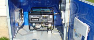
Figure 2. Ready-made welding generator, assembled with your own hands.
Work should begin with the manufacture of a frame for a gasoline engine and generator. For this, a metal corner 40 X 40 mm is used. The corners of the required length are cut with a grinder. Then, using an electric drill, holes are drilled into them for the motor and generator, which are secured using bolted connections.
To prevent the nuts from loosening, washers should be placed under them. The working circuit of the device is very simple. After the homemade welding is completely assembled, it looks like this: Figure 2.
Figure 3. Schematic diagram of the converter operation.
To make it easier to move the welding generator, wheels can be installed on the frame. They are attached either by welding or, after drilling holes in the frame, with mounting bolts. Torque is transmitted from the motor to the generator through a gearbox. Due to the rotation of the armature, an electric current arises in the stator winding. This electric welding scheme is inherent in the operation of all welding machines. Welding converters work on the same principle. The schematic diagram of the converter operation is as follows: Figure 3.
With the help of a network rectifier, alternating current is converted into direct current. After the line filter, the frequency is converted. Then, unlike a welding generator, in a converter the current passes through a transformer. Then it goes to the power rectifier.
Equipment for welding unit
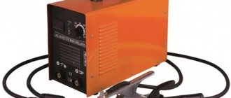
Compared to traditional devices, a three-phase inverter-type unit is compact, easy to use, and reliable. There is only one nuance that makes you think about it during the purchase - the rather high price.
Even superficial calculations suggest that making a welding machine with your own hands will be cheaper.
If you approach the selection of the necessary elements with all seriousness, then a homemade welding tool will last a long period of time.
In general, the welding machine circuit consists of three blocks: a rectifier block, a power supply and an inverter block.
A homemade AC and DC apparatus can be equipped so that it can be light in weight and have a small size.
A homemade welding machine can be easily built with your own hands, using objects available to everyone.
All the parts needed to create a welding unit are available in electrical equipment or in devices where some elements have failed.
You can build a simple current regulator from part of the heating coil used in an electric stove.
If you couldn’t find any necessary parts at all, then it’s okay - you can make them yourself.
A piece of copper wire can serve as a material for creating such an important element of a DC and AC welding unit as a choke.
Specifically for its assembly you will need a magnetic circuit, which has an old starter. You also need 2-3 copper wires with a cross-section of 0.9 - and you can get a choke.
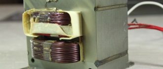
The transformer for the welding unit can be an autotransformer or the same part removed from an old microwave oven.
When removing the necessary element from it, you need to be careful not to damage the primary winding.
And the secondary one will have to be redone anyway; the number of new turns depends on the power of the unit being designed.
The rectifier is assembled on a board made of either getinax or textolite.
The diodes for the rectifier must correspond to the selected power of the unit. To keep them cool, an aluminum alloy radiator is used.
Sequential assembly of all parts
All elements of the welding unit must be located on a base made of metal or textolite strictly in their places.
According to the rules, the rectifier is adjacent to the transformer, and the inductor is located on the same board with the rectifier.
The current regulator is installed on the control panel. The frame itself for the structure of the unit is created from aluminum sheets; steel is also suitable for this.
You can also use a ready-made case, which previously protected the contents of the system unit of a computer or oscilloscope. The main thing is that it must be strong and solid.
A board with thyristors is placed at a great distance from the transformer. The rectifier is also not installed close to the transformer.
The reason for this arrangement is the strong heating of the transformer and inductor.
Thyristors mounted on aluminum radiators remove heat from the inductor. They even cancel out the heat waves emanating from the wires.
An electrode holder is attached to the outer panel, and a wire with a plug is attached to the rear panel to connect the unit to a household network.
The video in our article demonstrates how to assemble a welding unit with your own hands.
Under no circumstances should the elements of the unit be fixed close to each other, as they must be subject to airflow.
It is necessary to make holes on the sides of the frame from where air will flow. This is also necessary for installing a cooling system.
If the welding unit is constantly in the same place, then it is unlikely that anything will happen to it.
The current regulator, or more precisely, its handle fixed on the outer wall, will be able to work for a long time.
But portable mini-inverters that are taken for field work may be subject to mechanical shocks. Basically, the body of the product suffers from this, but there is a risk of the throttle falling off.
The product is assembled - it’s time to check how it functions. When testing the operation of the welding unit, temporary wires should not be used.
You need to check the product with standard contact cables.
During the very first connection to the network, look at the current regulator. It is important to ensure that there are no unfixed parts left.
If the unit is in good working order and free from defects, then you can start welding in various modes.
Features of winding windings.
There are the following rules for winding the windings of a welding machine:
- Winding should be done along an insulated yoke and always in the same direction (for example, clockwise).
- Each winding layer is insulated with a layer of cotton insulation (fiberglass, electrical cardboard, tracing paper), preferably impregnated with bakelite varnish.
- The terminals of the windings are tinned, marked, secured with cotton braid, and a cotton cambric is additionally put on the terminals of the network winding.
- If the wire insulation is of poor quality, winding can be done in two wires, one of which is a cotton cord or cotton thread for fishing. After winding one layer, the winding with cotton thread is fixed with glue (or varnish) and only after it has dried, the next row is wound.
The network winding on a rod-type magnetic core can be positioned in two main ways. The first method allows you to obtain a more “hard” welding mode. The network winding consists of two identical windings W1, W2, located on different sides of the core, connected in series and having the same wire cross-section. To regulate the output current, taps are made on each of the windings, which are closed in pairs.
The second method of winding the primary (network) winding involves winding a wire on one side of the core. In this case, the welding machine has a steeply falling characteristic, welds “softly”, the length of the arc has less influence on the value of the welding current, and therefore on the quality of welding.
After winding the primary winding of the welding machine, it is necessary to check for the presence of short-circuited turns and the correct number of turns. The welding transformer is connected to the network through a fuse (4...6 A) and if there is an AC ammeter. If the fuse burns out or gets very hot, this is a clear sign of a short-circuited turn. In this case, the primary winding must be rewound, paying special attention to the quality of the insulation.
If the welding machine makes a loud noise and the current consumption exceeds 2...3 A, then this means that the number of turns of the primary winding is underestimated and it is necessary to wind up a certain number of turns. A working welding machine should consume no more than 1..1.5 A current at idle, not get hot and not make a strong buzz.
The secondary winding of the welding machine is always wound on both sides of the core. According to the first winding method, the secondary winding consists of two identical halves, connected counter-parallel to increase the stability of the arc (Fig. 6 b). In this case, the wire cross-section can be taken slightly smaller, that is, 15..20 mm2. When winding the secondary winding using the second method, first 60...65% of the total number of its turns is wound on the side of the core free from windings.
This winding serves mainly to ignite the arc, and during welding, due to a sharp increase in magnetic flux dissipation, the voltage on it drops by 80...90%. The remaining number of turns of the secondary winding in the form of an additional welding winding W2 is wound on top of the primary. Being a power supply, it maintains the welding voltage and, consequently, the welding current within the required limits. The voltage across it drops in welding mode by 20...25% relative to the no-load voltage.
Winding the windings of a welding machine on a toroidal core can also be done in several ways.
Methods for winding the windings of a welding machine on a toroidal core.
| 1. Uniform; | 2. Sectional; |
| a – network winding; | b – power winding |
Switching windings in welding machines is easier to do with the help of copper tips and terminals. Copper lugs at home can be made from copper tubes of a suitable diameter with a length of 25...30 mm, securing the wires in them by crimping or soldering. When welding under different conditions (high or low current network, long or short supply cable, its cross-section, etc.), by switching the windings, the welding machine is adjusted to the optimal welding mode, and then the switch can be set to the neutral position.
general information
Every car has a built-in generator. It is a simple mechanical device that is capable of converting energy into electrical current. In cars, generators are needed to power all electrical equipment when the car is running. By the way, all car generators run on alternating current. This is important to know if you are going to weld from a generator.
If you don't know what a generator looks like or where it is located in the car, then you won't have a hard time finding it. It is located at the front of a petrol or diesel engine. If the car is a hybrid, then a “starter” type generator is used, since it plays the role of a starter. Also, similar generators are used in cars where the engine is started using the “start/stop” button.
Setting up the welding machine.
Having manufactured a welding machine, a home electrician must set it up and check the quality of welding with electrodes of various diameters. The setup process is as follows. To measure welding current and voltage you need: an AC voltmeter of 70...80 V and an AC ammeter of 180...200 A.
When welding with different electrodes, the values of the welding current – Iw and welding voltage Uw, which must be within the required limits, are taken. If the welding current is small, which happens most often (the electrode sticks, the arc is unstable), then in this case, by switching the primary and secondary windings, the required values are set, or the number of turns of the secondary winding is redistributed (without increasing them) towards increasing the number of turns wound on top of the network windings
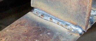
After welding, it is necessary to check the quality of welding: the depth of penetration and the thickness of the deposited metal layer. For this purpose, the edges of the welded products are broken or sawed. It is advisable to create a table based on the measurement results. Analyzing the data obtained, the optimal welding modes for electrodes of different diameters are selected, remembering that when welding with electrodes, for example, with a diameter of 3 mm, electrodes with a diameter of 2 mm can be cut, because The cutting current is 30...25% higher than the welding current.
Technological recommendations and safety measures.
The welding machine must be connected to the network using a wire with a cross-section of 6...7 mm through an automatic machine with a current of 25...50 A, for example AP-50.
The diameter of the electrode, depending on the thickness of the metal being welded, can be selected based on the following ratio: de=(1...1.5)*B, where B is the thickness of the metal being welded, mm. The arc length is selected depending on the diameter of the electrode and is on average equal to (0.5...1.1) de. It is recommended to weld with a short arc of 2...3 mm, the voltage of which is 18...24 V. Increasing the length of the arc leads to a violation of the stability of its combustion, increased losses due to waste and spatter, and a decrease in the depth of penetration of the base metal. The longer the arc, the higher the welding voltage. The welding speed is selected by the welder depending on the grade and thickness of the metal.
When welding with straight polarity, the plus (anode) is connected to the part and the minus (cathode) to the electrode. If it is necessary for less heat to be generated on the parts, for example, when welding thin-sheet structures, then reverse polarity welding is used. In this case, the minus (cathode) is connected to the part being welded, and the plus (anode) is connected to the electrode. This not only ensures less heating of the part being welded, but also accelerates the process of melting the electrode metal due to the higher temperature of the anode zone and greater heat input.
Welding wires are connected to the welding machine through copper lugs under the terminal bolts on the outside of the welding machine body. Poor contact connections reduce the power characteristics of the welding machine, deteriorate the quality of welding and can cause overheating and even fire of the wires.
With a short length of welding wires (4..6 m), their cross-sectional area must be at least 25 mm2.
During welding work, it is necessary to comply with fire safety rules, and when setting up the device and electrical safety - during measurements with electrical devices. Welding must be carried out in a special mask with protective glass grade C5 (for currents up to 150...160 A) and gloves. All switching in the welding machine must be done only after disconnecting the welding machine from the network.
Operating principle of the welding machine
Iron welding occurs due to the high temperature of the electric arc, which melts the electrode and the edges of the metal being joined.
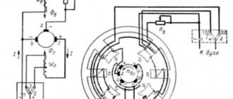
Figure 1. Operating principle of the welding machine.
Then the molten mass is mixed, and as it cools, the parts are joined. The schematic diagram of a welding generator is as follows: Figure 1, where: I is the generator armature; OYA - armature winding; OVN - magnetization excitation winding; R—rheostat; ORP - series excitation winding; D - electric arc.
After the arc ignites, welding current begins to flow in the armature circuit of the working circuit. It passes through the series field winding, thereby creating a magnetic flux. At this time, an electromagnetic force is created in the magnetizing excitation winding, which is directed in the opposite direction. The energy release that occurs when two EMFs collide is the source of the electric welding arc.
A welding generator can be used not only as a welding machine, but also as a source of backup lighting. To do this, you need to make an additional output and install a socket. The basic connection diagram does not change. The socket is mounted on the body of the device. This use of a welding generator is justified in those farms where disconnecting the main power grid can cause losses. For example, in incubators where chickens are raised.
Welding rectifier - features of operation and assembly
To perform certain types of welding work, for example, with stainless steel, the use of alternating current supplied by a transformer is not used. To work with such metals, a constant voltage supply is required. In addition, direct current cutting reduces the consumption of electrodes, and metal spattering is prevented during welding.
To perform work in such conditions, welding rectifiers are used, which allow welding with direct and reverse polarity current. If you have experience in installing electronic circuits, then you can also assemble such a device yourself.
The basis of the welding rectifier will be the same step-down transformer. The difference lies in the presence of a rectifying electronic circuit. If desired, you can remake the already described welding transformer or assemble a universal device that will allow you to weld with both alternating and direct current.
The simplest diagram of the electronic part of a welding rectifier looks like this:
Schematic diagram of a welding rectifier
When assembling such devices, the following design features should be taken into account:
- The main part of the device is a rectifier bridge made of powerful power diodes. They are connected according to the diagram, taking into account polarity.
- Smoothing of current ripple is carried out due to a filter made on the capacitor and choke coil. Please note that the components must have a margin of 2.5 - 3 permissible voltage.
- When working with high currents, the elements heat up. Semiconductor diodes are sensitive to overheating. Therefore, they are installed on radiators, which will increase the intensity of heat removal.
- When enclosing the device in a housing, it becomes mandatory to use a fan to increase cooling efficiency.
We pay attention to the connection of individual elements of the circuit. Considering that they will be exposed to high current, it is necessary to ensure reliable contact. If this is not done, then the wires in these areas will heat up and burn out. The preferred option is with fastening using platforms with a bolt and nut.
The choke in such designs is made in the form of a separate remote inductor, which is connected as needed. Note that installing a rectifier does not prevent the welding current from changing using the secondary winding coil position regulator.
As you can see, there are no difficulties in assembling a welding machine yourself. But it’s worth working on such devices only if you have experience in designing simple devices that operate with lower currents. Otherwise, entrust the assembly to a specialist or buy a factory welding machine.
Microwave welding machine:
Design of transformer and chokes
Wire winding diagram.
T1 is assembled from 3 “lines” from old TVs, folded together. Core PK30x16 made of ferrite grade 3000NMS-1. Windings “I” and “II” each have 2 sections with PSD 1.68 wire insulated with fiberglass. They are connected in series and have turns:
- winding “I” - 2×4;
- winding “II” - 2×2.
Winding “I” operates in the worst thermal conditions, so during assembly it is necessary to wind it with a pitch (gap) of 1 mm. In the second winding, do not forget to tap from the middle.
Both windings must be placed in such a way that the operation of the diodes VD11-VD34 is not disrupted. The winding direction of winding “I”, starting from the terminal connected to L2, is counterclockwise. And the winding direction of winding “II” is clockwise, from the terminal connected to VD21-VD34.
Winding “III” is a turn of wire 0.4-0.5 mm in insulation for a voltage of 500 V or more.
It is important to distribute the windings, maintaining the gaps correctly. This is necessary for cooling the magnetic circuit and for safety reasons. To do this, install 4 fiberglass (1.5 mm) plates, which are glued after adjustment.
Inductor L1, with an inductance of 40±10 μH, is wound on a PL core 12.5×25-50 with a gap (non-magnetic) of 0.3-0.5 mm and has 175 turns wound with PEV-2 type wire, caliber 1.32.
Choke L2 is a spiral without a frame, wound with 4 mm2 wire in thermal insulation. Number of turns -11, winding diameter -14 mm. A large current flows through the inductor and it needs to be blown through.
Toroidal apparatus
It is much lighter than usual. It is convenient to carry. Such devices are used where the ability to quickly transport is important.
Whatever device you choose, in any case, make it yourself:
- Interesting;
- Practical;
- Economical.
And, of course, it’s always nice to show a homemade welding machine to your friends. It will become a source of pride and an indispensable assistant in the household.
Repairing a welding machine with your own hands is also quite exciting.
How to make a welding machine from a car generator with your own hands? (video)
/ Equipment /
The forum has moved to a new engine, please report any functional problems or errors in translation in the thread
Authorization
Subscribers
Author Fnunovich, in Homemade welding and auxiliary equipment
general information
A generator, as a part built into any car model, is a fairly simple mechanism that converts energy into electricity. In cars, this element performs the function of powering electrical equipment during operation.
When using the automotive version for welding metals, it is important to remember that automotive models operate on alternating current.
Welding, in most cases, is performed with a constant type of current, which must be taken into account when working.
In order to find a generator in a car, you need to know what it looks like and where it is located. You need to look for it in the front of the engine. It doesn't matter whether this engine runs on gasoline or diesel.
If the car is a hybrid type, it has a built-in starter. In such cars it performs exactly this role. Generator modifications of the “starter” version are also built into models whose ignition is carried out with the “start/stop” button.
: DIY welding machine - everything you need to know
Operating principle of the welding machine
Iron welding occurs due to the high temperature of the electric arc, which melts the electrode and the edges of the metal being joined.
Figure 1. Operating principle of the welding machine.
Then the molten mass is mixed, and as it cools, the parts are joined. The schematic diagram of the welding generator is as follows: Figure 1, where:
I am the generator's anchor; OYA - armature winding; OVN - magnetization excitation winding; R—rheostat; ORP - series excitation winding; D - electric arc.
After the arc ignites, welding current begins to flow in the armature circuit of the working circuit. It passes through the series field winding, thereby creating a magnetic flux. At this time, an electromagnetic force is created in the magnetizing excitation winding, which is directed in the opposite direction. The energy release that occurs when two EMFs collide is the source of the electric welding arc.
Diagnostics of a homemade inverter and its preparation for operation
Making an inverter welding machine is half the battle. An equally important task is its preparation for work, during which the correct functioning of all elements is checked, as well as their settings.
The first thing you need to do when checking a homemade welding inverter is to apply a voltage of 15 V to the PWM controller and one of the cooling fans. This will allow you to simultaneously check the functionality of the controller and avoid overheating during such a test.
Checking the output voltage with a tester
After the capacitors of the device are charged, a relay is connected to the electrical supply, which is responsible for closing the resistor. If you apply voltage directly to the resistor, bypassing the relay, an explosion may occur. After the relay operates, which should happen within 2-10 seconds after applying voltage to the PWM controller, you need to check whether the resistor has shorted.
When the relays of the electronic circuit operate, rectangular pulses should be generated on the PWM board and supplied to the optocouplers. This can be checked using an oscilloscope. The correct assembly of the diode bridge of the device also needs to be checked; for this, a voltage of 15 V is applied to it (the current should not exceed 100 mA).
The transformer phases may have been incorrectly connected when assembling the device, which can lead to incorrect operation of the inverter and the generation of strong noise. To prevent this from happening, the correct phase connection must be checked using a dual-beam oscilloscope. One beam of the device is connected to the primary winding, the second to the secondary. The phases of the pulses, if the windings are connected correctly, should be the same.
Using an oscilloscope to diagnose an inverter
The correct manufacturing and connection of the transformer is checked using an oscilloscope and connecting electrical devices with different resistances to the diode bridge. Based on the noise of the transformer and the readings of the oscilloscope, they conclude that it is necessary to improve the electronic circuit of the homemade inverter apparatus.
To check how long you can continuously work on a homemade inverter, you need to start testing it from 10 seconds. If the device’s radiators do not heat up during operation for such a duration, you can increase the period to 20 seconds. If such a time period does not negatively affect the condition of the inverter, you can increase the operating time of the welding machine to 1 minute.
Maintenance of a homemade welding inverter
In order for the inverter device to serve for a long time, it must be properly maintained.
If your inverter stops working, you need to open its cover and blow out the insides with a vacuum cleaner. Those places where dust remains can be thoroughly cleaned with a brush and a dry cloth.
The first thing you need to do when diagnosing a welding inverter is to check the voltage supply to its input. If there is no voltage, you should check the functionality of the power supply. The problem in this situation may also be that the fuses of the welding machine have blown. Another weak link of the inverter is the temperature sensor, which, in the event of a breakdown, must not be repaired, but replaced.
A temperature sensor that often fails, usually located on a diode block or inductor
When performing diagnostics, it is necessary to pay attention to the quality of connections of the electronic components of the device. You can identify poorly made connections visually or using a tester. If such connections are identified, they must be corrected in order to avoid future overheating and failure of the welding inverter.
Only if you pay due attention to the maintenance of the inverter device can you count on it to serve you for a long time and enable you to perform welding work as efficiently and efficiently as possible.
We assemble a welding machine from a car generator with our own hands
Reading time: 3 minutes
A welding generator is a very necessary thing in the household. With its help, you can power not only an inverter, but also any other power tool found in the field. Welding generators also help out in the country, where the power supply is often unstable. But what if you don’t have a welding generator and need to do some welding? At the same time, you also do not have access to electricity.
In this case, a generator, which any modern (and not so modern) car has, will help. Yes, you can connect an inverter to the autogenerator. In this article we will tell you how to weld from a car generator and whether it is possible to assemble a welder from a generator with your own hands.