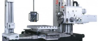
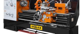
Purpose of cylindrical grinding machines
The low grain size of the processing tool ensures a slight roughness of the contact zone and high precision of work. When using machines for industrial purposes, the workpieces undergo primary temperature and mechanical treatment, so the allowance is minimal.
The capabilities of the machines are limited by performance characteristics. Using standard equipment it is impossible to work with parts whose taper exceeds 6º. The design of modern machines makes it possible to process the outer surface of any workpiece due to the design of the front and grinding headstocks, which can rotate around their axis.
As a rule, cylindrical grinding machines are used at the finishing stage of processing.
Features of some components of the 3B12 machine
Bed (unit 10-00/ЗБ153)
The bed is a rigid cast iron box-shaped casting. On the upper front part of the frame there are guides (one is flat, the other is V-shaped) on which the table is installed.
The upper right and rear left parts of the frame are made in the form of processed plates, on which the slide and electrical cabinet are installed.
The rear part of the frame is made in the form of a trough for collecting coolant into the tank.
The front wall of the frame is processed and serves for mounting the mechanism for manual movement of the table, periodic feed mechanism, control handle, hydraulic panel and control panel. The mechanisms are covered with casings, and the control handles are brought out.
The compartments inside the bed are closed with doors or covers, which provides access to the mechanisms located inside the machine.
Table (unit 20-00/ZB153)
The table assembly consists of a lower and an upper table.
The lower table is a cast iron. Its lower part is made in the form of flat and V-shaped guides. The upper part is the base for the upper table. On the front of the lower table there is a T-shaped groove for attaching movable stops. The ends of the lower table are made in the form of wings that protect the frame guides. The upper table is located on the upper base surface of the lower table.
The top table is a cast iron with stiffening ribs. The side walls of the table form a trough for coolant. The upper table is connected to the lower one using a spherical pin, around which the upper table rotates, and two clamps for clamping the upper table in the desired position. The rotation of the upper table relative to the lower one is carried out using handle 21 (Fig. 3). When the handle rotates, the screw moves the rack and the upper table rotates through the lock 20. The amount of rotation is controlled by a scale or an indicator mounted on the bracket.
Mechanism for manual movement of the table (unit 30-00/3B153)
The mechanism for manual movement of the table (Fig. 5) serves for longitudinal movement of the table (product).
According to the work performed, the mechanism has two speeds of movement:
- Slow table movement S=1.59 mm/flywheel revolutions
- Accelerated table movement S = 31.9 mm/flywheel revolutions
The mechanism for manual movement of the table consists of planetary and spur gearboxes (gear blocks 6, 9, 10, gears 3, 4, 5), shift handle 7, locking hydraulic cylinder with axis-rod 2 and flywheel 11.
When the table moves automatically, the manual movement mechanism is automatically turned off by moving the axis-rod 2 of the hydraulic cylinder, which disengages the gear block 10 from gear 4.
The mechanism for manual movement of the table is mounted in a cast iron body 1 and is attached to the left frame symmetrically to the periodic feed mechanism.
When handle 7 is positioned away from you, the planetary gearbox is turned on, rotating the flywheel. The table moves slowly.
When the handle 7 is positioned towards itself, block 6 disengages from gear 5, engages with gear sector 8, which is attached to flywheel 11, but remains engaged with block 9. Thus, block 6 rigidly connects gear z=28 to the flywheel block 9. The movement is transmitted directly to the spur gearbox. The table moves quickly.
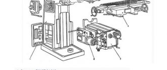
Grinding head (unit 40—00)
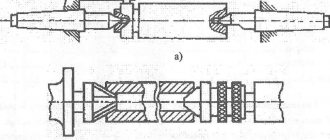
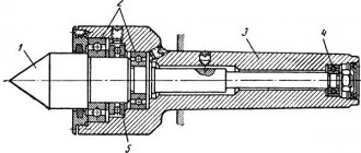
The grinding headstock (Fig. 6) consists of a massive cast-iron body on which external 8 and internal 1 grinding spindles with drives are mounted.
The external grinding spindle is mounted on two three-liner plain bearings 10.
The liners 4 rest on pins with a spherical surface 3, which allows the liners to self-align in both axial and radial directions. This creates favorable conditions for the formation of an oil wedge.
To regulate the size of the diametrical gap and align the position of the spindle axis relative to the frame guides, the pins 3 have a thread with which they can move in the radial direction.
The external grinding spindles are driven from an electric motor 6 by a two-strand V-belt transmission. The spindle is limited by its shoulder from moving in the axial direction. The collar is pressed through ring 9 by springs to glass 11, which is rigidly inserted into the body. Thanks to this design, it is possible to process parts with the end of a grinding wheel.
The external grinding spindle is lubricated through pipes 5 from a special unit located outside the frame.
A folding bracket 2 for internal grinding is installed on the body of the grinding headstock, in which the internal grinding spindle 1 is fixed.
The grinding wheel can be rotated on the slide at an angle of ±90°. In addition, the upper part of the grinding headstock can be moved relative to the slide by turning the shaft 7 with the gear with a wrench, having previously loosened two screws 14. This movement of the grinding headstock makes it possible, by turning the headstock 90°, to grind the end of the part using the periphery of the grinding wheel. This expands the technological capabilities of the machine.
At the bottom, to the plate of the grinding headstock, a bracket 13 with a hydraulic cylinder for quick removal of the grinding headstock and a hydraulic lock are attached, which prevents the supply of the grinding headstock when the machine is turned off. The headstock is quickly supplied using a weight when the pressure in the quick release hydraulic cylinder drops.
The grinding headstock runs on roller guides 12.
Sled (unit 41-00)
The body of the slide 1 is cast iron (Fig. 7) in the upper part has processed plates for fastening steel flat and V-shaped rolling guides, on which the grinding head is installed.
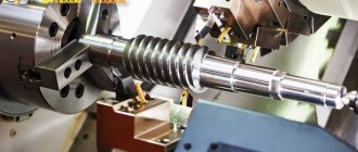
A cylindrical gearbox is mounted in the slide body, which serves to transmit rotational motion from the periodic feed mechanism to the feed screws 6 and the installation movement 11.
When working with periodic automatic feed or manually, rotation from the ratchet wheel of the periodic feed mechanism is transmitted through gears 2 and 3 to the splined shaft 8, on which a double block of gears 5 sits. From block 5 through gear 4, rotation is transmitted to the feed screw 6 in the forward position. The feed screw can move the thrust washer 9 by 0.6 mm. The grinding head, pressed by a weight to the feed screw, through the splined sleeve 13 and the set screw 11, moves after the feed screw until the thrust washer 9 meets three stops 7. The feed screw, rotating further, breaks the contact. A light signal turns on indicating that the supply has stopped.
When setting the machine to a certain grinding diameter, the block switch handle with rod 12 is pushed in all the way. In this case, the gear block 5 moves to the extreme right position and engages with gear 10. Gear 10 is rigidly connected to the set screw 11. When the flywheel of the periodic feed mechanism rotates, the set screw rotates and the grinding headstock is installed in the desired position.
Headstock (unit 50-00)
The headstock (Fig. consists of a rotating cast iron body, which is attached with bolts 12 to the slide 11. The headstock rotates toward the worker by 30° and away from the worker by 90°.
The work is carried out both in a stationary spindle 9 (in the centers) and in a rotating spindle (in the chuck). Rotation from electric motor 1 is transmitted through a V-belt drive to pulley 3. Rotation from the pulley to the product is transmitted through faceplate 5 and driver 4. When working in the centers, spindle 9 is fixed using lock 2.
When working in a chuck, the spindle is connected to the spindle 9 through a faceplate 5 using a screw (used to fasten the driver). Instead of the center 6, a faceplate with a chuck 7 is inserted into the conical hole of the spindle and tightened with a screw 13.
The spindle 9 is mounted on rolling bearings 10.
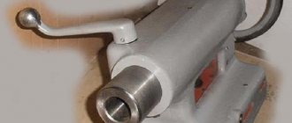
Tailstock (unit 51-00)
The tailstock (Fig. 9) consists of a box-shaped cast iron body 4, in which a system of levers 8 is mounted for supplying and removing the quill 3 with the center.
The tailstock is secured with two bolts in the required location to the upper turntable.
The quill is retracted using handle 1 through a system of levers. The design of the levers allows the quill to be fixed in the retracted position and when retracted manually. The fixation is adjusted with screw 6.
The quill is supplied using spring 5, the force of which is adjusted by screw 2. The screw has a through hole through which the rear center can be pushed out.
Intermittent feed mechanism (unit 60-00)
The periodic feed mechanism (Fig. 10) is mounted on the front wall of the right side of the frame. The mechanism provides manual and automatic periodic feeding to a hard stop or to zero marks on the dial.
Manual movement is carried out by turning flywheel 1 through shaft 4, which is connected with the splined end to the gears of the slide (Fig. 7).
Periodic feeding is carried out using a pawl 5 and a ratchet wheel 2. The feed amount is set with a handle 7 within the range of 0.002-0.024 mm.
The amount of allowance to be removed is set by dial 3 on flywheel 1. When the dial is in the zero position, visor 8 closes ratchet wheel 2 and the feed stops.
Manual push feed is carried out using pawl 6 (handle 22 in Figure 3).
Types of cylindrical grinding equipment
In the process of developing metalworking technology, the production of the following types of cylindrical grinding machines was launched:
- The classic type involves installing the workpiece in centers. The role of clamps is performed by the front and tailstocks. As soon as work begins, the part begins to rotate thanks to the drive of the apparatus. Metal removal occurs when the abrasive disc comes into contact with the surface. The method for removing metal shavings depends on the model of the device.
Such models are popular with various repair shops. For example, this equipment is used to grind crankshafts of internal combustion engines.
- The centerless design is considered universal, since the product being processed is mounted on a special carriage. On one side it is fixed to prevent the part from moving during processing. An auxiliary circle is used as fastener. Grinding is performed on the back side of the part. This allows you to work with hollow cone-shaped products.
CNC cylindrical grinding machines deserve a separate description. Process automation increases productivity by reducing the role of the equipment operator. In addition, the quality of processing increases significantly, since automatic feeding increases the accuracy of work - the permissible error does not exceed hundredths of millimeters. Software control reduces the likelihood of defects.
Purpose
Cylindrical grinding machines are used to process the outer cylindrical surface; the workpiece is fastened in the centers and in the chuck. In this case, longitudinal and transverse feeding can be carried out to achieve the desired result. The universal version is suitable for various sizes; some types can be used in industry to produce particularly large parts.
During operation of a universal machine with centers, the direction of rotation of the workpiece is opposite to the direction of rotation of the abrasive material. Such models can be used in various types of production.
It is worth noting that the cylindrical grinding machine is used at the final stage of production. Centerless and other types of models carry out grinding after turning, milling, drilling and so on.
Device and design features
The design of cylindrical grinding machines depends on the working materials and quality requirements for the finished products. The following accuracy classes of devices are distinguished:
- increased accuracy;
- high precision;
- especially high precision.
The machines are used for processing various materials: from cast iron, steel and alloys based on them to high-strength materials - polycrystalline diamonds and cubic nitrides.
Let's consider the design features of various devices and the most common layout options.
Working nodes
Regardless of the type of design, the main elements of cylindrical grinding machines are:
- bed;
- Desktop;
- grinding and headstock;
- control mechanisms.
The drive to the spindle is mounted in the headstock, and the drive to the wheel is mounted in the grinding headstock.
The main element of the control mechanism is the push-button station. Flywheels are responsible for manual movement of the work table and spindle head, which are controlled using the following handles and stops:
- fast feed of the headstock;
- moving the quill;
- adjustable desktop speed;
- disabling automatic table movement and reverse.
In addition to the above components and parts, the following elements play an important role:
- Grinding headstock. Differs in rigidity of a design. Depending on the layout of the machine, it can be a fixed or movable element. It contains a spindle mounted on hydrodynamic or other supports.
- Balancing mechanism. Reduces oscillatory processes during the working cycle. There are models with both manual and automatic machine balancing.
Automatic balancing is performed using switchable spindle stiffness or additional balancing weights.
- Working tool editing mechanism. Adjusts the shape of the contact tool and maintains its functionality.
- Feeding unit. Responsible for moving the grinding wheel.
- Tailstock. It is one of the design elements of machines for which the working location of the workpiece is installation in the centers.
- Lunettes. Special supports for working with long parts.
Possible layout options
The most common ways to configure cylindrical grinding machines are:
- cartridge;
- center;
- centerless.
An important factor is the presence of a second table. In centerless models, the shoe is a fixed element.
In some machines, the support knife is mounted on the leading stock slide. In this case, it moves simultaneously with the grinding tool relative to its axis.
Fixed knife models have found their application on automatic assembly lines. They are valued for their high quality characteristics, because this arrangement ensures the stability of the workpiece axis, regardless of the condition of the machine’s grinding tool. The design of such equipment is characterized by high technological complexity due to the movable headstock and the mechanism for its movement.
Main settings
When choosing equipment, you should take into account its type, which determines many important grinding parameters. The main parameters include:
- Possible dimensions of the installed center. In the case of a centerless model, an important indicator is the size of the table.
- The diameter of the circle and the speed of its rotation. Universal design options can be used to produce parts of various shapes; they can be conical.
The passport contains all important information. The drawing and passport allow you to determine what technical characteristics the design has. The drawings are drawn up taking into account GOST, just like the passport.
The above information should be taken into account when choosing a model; the diagram of a cylindrical grinding machine reflects all its features. Therefore, to determine important points, you should consider the drawings and passport drawn up in accordance with GOST.
Principle of operation
There are several methods of external processing, which depend on the technical parameters of metalworking equipment.
In repair shops, the longitudinal grinding method is most often used. In this case, the workpiece to be processed must be secured in the centers of the machine. An electric motor rotates the headstock along with the fixed object. Longitudinal movement is performed by the feed mechanism, changing the position of the workpiece relative to the grinding wheel.
In addition to longitudinal grinding, the following processing methods can be performed on modern machines:
- Deep. The amount of allowance in one pass can reach 0.4 mm of metal. The impact on the surface is carried out by the conical part of the tool.
- Mortise. This technology involves the use of wide grinding wheels to perform roughing or finishing work. During processing, the position of the workpiece relative to the circle does not change.
- Ledges. The method combines deep-feed and plunge grinding. This makes it possible to process products of complex shapes.
Types of machines
According to the mounting method, a universal cylindrical grinding machine can be:
- cartridge;
- center;
- centerless (several surfaces are polished at once).
According to the basing scheme, there are 2 types of units:
- on shoes with end driving support;
- with support knife.
During pass grinding, the cylinders are completely stripped off. The shape of the part does not change. With the mortise method, the shape depends on the degree of wear of the wheel. Such units are used for processing shaped, stepped workpieces, surfaces with collars, and for simultaneous processing of the end and neck of the product.
Important equipment parameters and technical specifications
The main parameters are indicated in the manufacturer's passport. These include:
- Electric drive power. The performance of the device depends on the value of this parameter. The unit of measurement is kW.
- Voltage. Defines the scope of use. Compact models for household work operate on a home network with a voltage of 220 V. Industrial machines operate on a voltage of 380 V.
- Desk dimensions. Limit the dimensions of processed workpieces.
- Maximum grinding wheel diameter. Its dimensions are determined by the interstate standard.
- Nominal speed. The rotation speed of the tool depends on this indicator.
- Availability of CNC and precision processing. Numerical program control allows you to increase the accuracy of the work performed, but the cost of such devices is quite high.
Arrangement of components of the grinding machine 3151
Arrangement of components of the grinding machine 3151
List of main components of the grinding machine 3151
- A - headstock of the product;
- B - grinding head;
- B - tailstock;
- G - bed;
- D — hydraulic drive of the table;
- E - table;
- F—rotary plate.
3151 Cylindrical Grinder Controls
- handwheel for manual transverse movement of the grinding head;
- table hydraulic drive control handles;
- handwheel for manual longitudinal movement of the table;
- push-button station.
What to look for when choosing a cylindrical grinding machine
At the equipment selection stage, it is necessary to pay attention to the standard equipment and the possibility of its modification.
As an example, consider the R-grind 1660 CNC CNC cylindrical grinding machine. The standard package includes:
- X-axis linear scales;
- grinding wheel with flange;
- diamond pencil for editing the circle;
- a set of auxiliary tools;
- carbide center;
- hydrostatic bearings on the spindle;
- coolant supply system;
- hydraulic oil cooling system;
- lighting of the work area.
The supplier offers the following elements as additional equipment for the machine:
- device for internal grinding work;
- set of driving mandrels;
- lunettes;
- self-centering chuck;
- stand for balancing the grinding wheel;
- device for automatic wheel balancing;
- control measuring sensor;
- filtration system for coolant.
Modifying a cylindrical grinder can increase the final cost by 20-30%.
External surface grinding machines are a popular product in the metalworking market. The presence of CNC allows you to increase the accuracy and productivity of work, but increases the cost of production. Do you think it makes sense to purchase a CNC machine for a small workshop or would such a purchase be impractical? Write your opinion in the comments.
Device
Equipment with fixed knives is used for automatic lines. A cylindrical grinding machine for metal can have different configurations. The most common arrangement is with 3 types of cartridges. These are cartridge ones with 1-2 tables, center ones with 1-2 tables. There are also centerless installations with fixed or movable knives and a fixed shoe.
The installation axis of the part will be constant in any position of the working grinding wheel, which guarantees high quality processing. When the unit wears out, no further adjustment is needed, and no loss of grinding quality is observed. However, the design of such machines is more complex. Machines with fixed heads are characterized by increased rigidity, but the dimensions of the unit are smaller, which allows the equipment to be used not only in workshops, but also in small workshops.
Purpose of the machines
Using a grinding machine, you can process wood, stone, plastic, and metal. It is designed to perform various technological operations:
- Processing of cylindrical, rectangular, triangular, square workpieces. Removing different layers of metal.
- Creating a rough surface. For this purpose, a special type of abrasive is selected.
- Sharpening cutting tools, accessories. To avoid damaging the cutting edge, water cooling is used.
To process cylindrical parts, you need to select the grain size of the abrasive material. The layer of metal, wood, plastic, stone that is removed depends on this. The smaller the particles, the more precise grinding occurs.
Description of the main components of the V-88 cylindrical grinding machine
- Bed - B 88.01.001
- Table - B 88.02.001
- Front headstock - B 88.03.001
- Rear headstock - B 88.04.001
- Cross feed mechanism - B 88.05.001
- Longitudinal feed mechanism - B 88.06.001
- Grinding head - B 88.07.001
- Headstock for internal grinding - B 88.08.001
- Electrical equipment - B 88.09.001
- Cooling - B 88.10.001
- Lunette - B 88.11.001
- Wheel straightening device - B 88.12.001
- Faceplate - B 88.13.001
B-88 machine bed (drawing B 88.01.001)
The main parts of this unit are the bed itself and the cabinet, which have a T-shape in plan. The internal cavity of the cabinet is used to install starting electrical equipment, for access to which there is a window in the front wall of the cabinet that is closed with a lid.
On the top of the frame there are front flat and rear prismatic guides for installing the table. The guides are equipped with four pockets for lubricant, which is supplied to the rubbing surfaces by means of spring-loaded rollers (parts 107 and 108).
On the front wall of the frame there is a processed plate for fastening the longitudinal and transverse feed mechanisms.
There is a machined area on the back of the upper wall of the bed to install the grinding head.
Table (drawing B 88.02.001)
The table assembly consists of a lower table with guides for moving along the frame and an upper one for turning the table.
The lower table is molded integrally with the visors covering the frame guides when the table is in its extreme positions. A rail is screwed to the bottom of the table to move the table along the frame guides.
On the front of the table there is a processed plate for attaching longitudinal movement stops.
On the upper plane of the lower table there are plates - supports for the upper table with a rotation axis in the middle; Along the edges there are pads for clamping and the upper table. On the right block there are two scales for counting the angles of rotation of the upper table: one - in degrees, the second - in taper values, referred to 100 mm of the length of the product.
To accurately set the angle of rotation of the upper table, use a screw (part 106).
The upper table is made with guides for installing the front and rear headstocks, which are fastened to the guides using a T-shaped groove.
Front headstock (drawing B 88.03 001)
The headstock with its base is installed on the guides of the upper (rotary) table and is attached to it using a block (part 150) and a bolt (part 154). The headstock body can be rotated around its axis (part 144).
After turning to the required angle, measured on the scale marked on the base of the headstock, the headstock body is secured using two groove bolts (parts 152 and 153).
To accurately set the headstock body to the zero position, as well as to rotate it to the required angle, use adjustable stops (part 147).
To drive the headstock, a flange electric motor mounted on a bracket (part 014) is used. By moving the bracket with el. The engine regulates the tension of the drive belt.
The headstock drive chain includes a friction clutch, the structure and operation of which is as follows:
On the clutch shaft (part 126), connected to the electric motor shaft, a two-stage drive pulley (part 129) with a brake drum (part 128) having an internal conical surface, to which the cone is pressed by the force of the spring (part 140) is mounted on ball bearings (part 127), connected by two keys to the shaft (part 126).
When using the handle (D61-1) to turn the sector (part 134) engaged with the teeth of the pressure cup (part 125), the latter, turning around the bushing (part 124), moves axially to the right and acts on the cone (part 127), which as a result comes out of contact with the drum (part 128).
At the same time, under the action of the spring (part 137), the brake lever (part 136) comes into operation, which slows down the drive pulley, and with it the headstock spindle.
The movement of the pressure cup (part 125) in the axial direction is achieved due to the presence of four wedge cams on its left end.
The transmission of rotation from the drive pulley (part 129) to the spindle pulley (part 104) is carried out using a V-belt, when rearranged on the pulley steps, the spindle can be given two different rotation speeds.
The design of the headstock provides the ability to work both with a rotating spindle (work using centers or a collet clamp), and with a stationary spindle and a rotating drive faceplate.
Drawing B 88.03.001 in section along AA (option-1) shows the position of the parts in the case of working with fixed centers.
When working with a rotating spindle (using centers or a collet clamp), the following must be done:
- a) unscrew the screw (part 115) until its shank comes out of the spindle groove
- b) unscrew the screw (part 118) and through the opened hole, screw the screw (part 119) all the way so that its shank fits into one of the 3 holes of the pulley (part 104)
- c) put the screw (part 118) in place
Rear headstock (drawing B 88.04.001)
The design is typical for cylindrical grinding machines; it is attached to the rotary table guides with a groove bolt. The quill retraction is lever-type and is carried out using a handle (part 012). The quill is pressed against the product by a spring. A screw (part 105) is used to push out the center.
The quill can be secured in a certain position using the handle (D61-4)
Cross feed mechanism (drawing B 88.05.001)
The mechanism is driven manually and is located on the front wall of the frame. The grinding head is installed on the upper plane of the caliper (part 011), which moves along the guides of the rotary plate (part 012).
The latter, together with the support and the grinding head, can be rotated at an angle of ±45° relative to the bottom plate (part 013), mounted on the bed plate.
The support with the grinding head is moved by rotating the flywheel (part 015) mounted on the shaft (part 101).
A worm (part 128) is installed at the rear end of the shaft, working in tandem with a worm gear (part 019) mounted on the lower end of a rack and pinion gear (part 132), which meshes with the rack (part 131).
The feed amount is measured by the dial ring (part 112), which sits loosely on the flywheel disk (part 113). For one revolution of the flywheel, the amount of movement of the caliper is 0.75 mm (reduction in the diameter of the product by 1.5 mm), the price of one division of the dial is 0.0025 mm.
To count the fine feed value, use the second dial, located in front of the main one, with a division value of 0.001 mm.
Fine feed is carried out using a handwheel (part 016), a worm (part 120) and a worm gear (part 017), freely sitting on the shaft (part 101).
Switching the drive from coarse feed to fine feed and vice versa is carried out by a handle (D 61-3) connected to a cam (item 103) that controls the rocker (item 105).
The link with its bevels acts on the expansion pins (parts 114 and 118), which, moving under the action of the link, enter with wedge-shaped ends into the cuts of the friction rings (parts 111 and 117), causing the latter to expand.
Thanks to this, the limb ring (part 112) or the worm gear (part 017) are connected to the shaft (part 101).
In drawing B 88.05.001 the parts are shown in the position corresponding to the included fine feed, i.e. the friction ring (part 117) is released and the worm gear (part 017) is connected to the shaft (part 101), and the dial ring (part 112) can freely rotate around the disk (part 113). To fix the dial ring (part 112) in the zero position, use the valve (part 141), which must be moved to the right using the handle (D 61-2) so that the cracker (part 143), fixed to the dial ring, entered the groove of the valve.
To turn off fine feed and turn off coarse feed, you need to move the cam (part 103) using the handle (D 61-3) to the position shown by the dash-dot line.
In this case, the rocker (part 105) will move to the right, compressing the spring, the pins (parts 114- and 118) will take a position in which the worm gear will be released, and the limb ring will be connected to the shaft (part 101).
After this, if the limb ring was fixed, move the valve to the extreme left position.
Longitudinal feed mechanism (drawing B 88.06.001)
Designed to move the table along the bed guides and is attached to the left side of the front wall of the bed.
The movement of the table is carried out using a flywheel (part 013) through gears (parts 102, 107, 108, 110) and a rack and pinion gear (part 111), coupled with the table rack.
For smooth table movements in the case of face grinding, a fine longitudinal feed device is provided, similar in design to a similar device for transverse feed.
Fine longitudinal feed is carried out by a handwheel (parts 05, 016); turning on the fine feed is done using the handle (D 61-3; 48×8) by moving it to the position shown in drawing B 88.06.001 with a dash-dot line.
On the front side of the mechanism panel there is a stop (part 113) that limits the movement of the table.
Grinding head (drawing B 88. 07 001)
It is installed on the upper plane of the cross-feed mechanism support and secured to it with two groove bolts (part 112).
The spindle head housing has a platform for installing a sub-motor plate (part 013) with an electric motor.
The transmission of rotation from the electric motor to the spindle is carried out by two V-belts.
To maintain the required peripheral speed of the grinding wheel as it operates, replaceable electric motor pulleys are provided. When working with a new grinding wheel on the shaft el. The engine must be fitted with a pulley dia. 70 mm and only when the circle is worked to a diameter of 190 mm can a pulley dia. 92 mm.
It is strictly forbidden to install on email. engine pulley with a diameter of 92 mm when working with a new circle having a diameter of more than 190 mm. An exception may be made for wheels intended for high-speed grinding.
The spindle supports are two adjustable bimetallic plain bearings. Axial play of the spindle is selected by a double-row thrust ball bearing mounted at the rear end of the spindle.
Oil is supplied from the crankcase to the spindle bearings using lubricating rings.
Oil is poured into the crankcase and headstocks through the plug (part 111) to the level of the marks and oil indicators located on the front wall of the headstock.
The grinding wheel is protected by a guard (part 014).
Email The engine and drive belts are covered with a casing.
Headstock for internal grinding (drawing B 88. 08. 001)
Installed as needed in place of the grinding headstock B 88.07.001.
The headstock body has a split boss in front for installing a grinding spindle. dividing, there is a platform at the rear for the electric motor. The transmission of rotation from the electric motor to the spindle is carried out by a flat cotton paper belt.
Electrical equipment (drawing B 88. 09. 001)
The electrical equipment of the machine is designed for connection to an alternating current network with a voltage of 220/380 volts and consists of:
- Starting electrical equipment mounted inside the machine cabinet.
- Local lighting lamps.
- Electric drive systems.
- a) The grinding wheel spindle is driven electrically. 1M motor, which is turned on and off using a 1K magnetic starter. Electrical connection The motor is connected to the mains using a plug.
- b) The drive of the headstock for internal grinding is carried out electrically. 1aM engine. The headstock for internal grinding is installed as needed in place of the grinding headstock, and el. The 1M engine is disconnected from the network using a plug and the electric power is turned on. 1aM engine.
- c) The headstock spindle is driven electrically. 2M motor, which is started and stopped by a 2K magnetic starter.
- d) The cooling pump is driven electrically. 3M motor controlled by 3K magnetic starter.
The machine's electric motors are started using the universal switch UP-5312 in the following sequence: first, the electric motor is turned on. engine 1M (1aM), then alternately 2M and 3M.
Power supply local lighting lamps are produced through a step-down transformer TPB-50.
Location of controls for the V-88 grinding machine
Location of controls for the V-88 grinding machine
List of controls for the V-88 grinding machine
- Universal switch for controlling machine motors
- Local lighting switch
- Plug for turning on electric power. grinding head motor
- Headstock clutch engagement handle
- Front center traction flywheel
- Longitudinal feed flywheel
- Fine longitudinal feed switch handle
- Fine longitudinal feed flywheel
- Longitudinal feed stop handle
- Longitudinal feed stop
- Cross feed handwheel
- Fine cross feed switch handle
- Fine cross feed handwheel
- Cross feed dial lock handle
- Tailstock bolt
- Tailstock quill retraction handle
- Tailstock quill clamp handle
- Rear center pusher flywheel
- Table rotation screw
- Table rotation bar clamp
- Headstock Spindle Lock Screw
- Headstock mounting bolt
- Bolt securing the rotating part of the headstock
- Headstock rotation stop
- Grinding head bolt
- Coolant valve
- Bolt securing the rotating part of the grinding headstock
- Batch switch for electric reverse. headstock motor
Technical characteristics of the V-88 machine
| Parameter name | 3У10А | B-88 |
| Main settings | ||
| Accuracy class according to GOST 8-82 | A | |
| Largest diameter of the installed product, mm | 100 | 140 |
| Maximum length of the installed product (RMC), mm | 160 | 180 |
| Maximum grinding length, mm | 140 | 180 |
| Largest grinding diameter, mm | 0..40 | |
| Smallest grinding diameter, mm | ||
| Recommended grinding diameter, mm | 3..15 | |
| Largest diameter of the hole to be ground, mm | 40 | |
| Recommended hole grinding diameter, mm | 3..15 | 25..50 |
| Maximum length of hole grinding, mm | 50 | |
| Distance from the axis of the headstock spindle to the table mirror - height of centers, mm | 120 | |
| Maximum weight of the installed product, kg | 1 | |
| Height of headstock centers above table, mm | 100 | 95 |
| Height of centers above the machine sole, mm | 1070 | |
| The largest diameter of the clamping chuck, mm | 100 | |
| Machine bed and table | ||
| Maximum longitudinal movement of the table, mm | 200 | |
| Maximum number of double table moves per minute, mm | 30 | |
| Minimum table travel between stops, mm | 1,5 | |
| Manual slow movement of the table per revolution of the flywheel, mm | 0,176 | |
| Manual accelerated movement of the table per revolution of the flywheel, mm | 2,5 | |
| Speed of automatic table movement (from the hydraulic system), m/min | 0,025..1,0 | No |
| Maximum angle of rotation of the upper table clockwise, degrees | 6 | 10 |
| Maximum angle of rotation of the upper table counterclockwise, degrees | 7 | 90 |
| Upper table rotation scale division value, deg | ||
| Scale division of the upper table (taper), mm/m | ||
| Grinding head | ||
| Maximum movement of the grinding head along the feed screw, mm | 100 | 80 |
| Displacement of the grinding head during rapid approach, mm | 15 | No |
| Angle of rotation of the grinding head clockwise, degrees | 30 | 45 |
| Angle of rotation of the grinding head counterclockwise, degrees | 30 | 45 |
| Time for rapid approach of the grinding head, s | 3 | No |
| Grinding wheel according to GOST 2424-67 | PP250x20x76 | 250 x 25 |
| Grinding wheel wear in mm per diameter | 80 | |
| External grinding spindle rotation speed, rpm | 2800 | |
| Jog feed - periodic feed with table reversal, mm | 0,00125 | |
| Manual jog feed - periodic feed at the moment of table reverse, mm | 0,00125 | No |
| Automatic jog feed - periodic at the moment of table reverse, mm | 0,0025..0,01 | No |
| Maximum stroke of automatic feed, mm | 0,25 | No |
| Transverse feed dial division price, mm | 0,0025 | 0,0025 |
| Fine cross feed dial division price, mm | 0,001 | |
| The amount of transverse movement of the grinding head per one revolution of the flywheel, mm | 0,5 | 0,75 |
| Maximum movement of the grinding head along the microfeed chain, mm/rad | 0,05 | |
| Speed limits of mortise microfeed, mm/min | 0,01..0,1 | No |
| Speed of fast installation movement of the grinding head, mm/min | No | |
| End of the grinding spindle according to GOST 2323-67 (taper 1:5, nominal diameter), mm | 32 | |
| Internal grinding attachment | ||
| The largest diameter of the workpiece installed in the chuck, mm | 60 | |
| Maximum length of the hole to be ground, mm | 85 | |
| Diameter of internal grinding head, mm | 20..45 | |
| Maximum width of the internal grinding head, mm | 16 | |
| Speed of internal grinding spindle | 40000..80000 | |
| Headstock (product headstock) | ||
| Product rotation speed (stepless regulation), rpm | 85..1000 | |
| Angle of rotation of the chuck clockwise, degrees | 30 | |
| Angle of rotation of the chuck clockwise, degrees | 90 | |
| Headstock spindle cone according to ST SEV 147-75 | Morse 3 | |
| Tailstock | ||
| The amount of retraction of the tailstock quill by hand, mm | 15 | |
| Tailstock quill spindle cone according to ST SEV 147-75 | Morse 2 | |
| Drive and electrical equipment of the machine | ||
| Number of electric motors on the machine | 7 | 4 |
| Grinding head spindle electric motor, kW (rpm) | 1,1 | 0,6 (2800) |
| Product drive electric motor, kW | 0,245 | 0,18 (1400) |
| Electric motor driving the internal grinding spindle, kW | No | 0,4 (2800) |
| Table drive electric motor, kW | 0,245 | No |
| Hydraulic pump electric motor, kW | 0,75 | No |
| Magnetic separator electric motor, kW | 0,06 | No |
| Paper pulling motor kW | 0,18 | No |
| Electric motor of the cooling system pump, kW | 0,12 | 0,125 (2850) |
| Overall dimensions and weight of the machine | ||
| Overall dimensions of the machine (length x width x height), mm | 1250 x 1400 x 1690 | 1140 x 920 x 1350 |
| Weight of the machine with electrical equipment and cooling, kg | 1980 | 580 |
- Alperovich T.A., Konstantinov K.N., Shapiro A.Ya. Design of grinding machines, 1989
- Alperovich T.A., Konstantinov K.N., Shapiro A.Ya. Setup and operation of grinding machines, 1989
- Dibner L.G., Tsofin E.E. Sharpening machines and semi-automatic machines, 1978
- Genis B.M., Doctor L.Sh., Tergan V.S. Grinding on cylindrical grinding machines, 1965
- Kashchuk V.A., Vereshchagin A.B. Grinder's Handbook, 1988
- Kulikov S.I. Honing, 1973
- Lisova A.I. Design, adjustment and operation of metal-cutting machines, 1971
- Loskutov V.V. Grinding machines, 1988
- Lurie G.B. Grinding machines and their adjustment, 1972
- Lurie G.B. Design of grinding machines, 1983
- Menitsky I.D. Universal sharpening machines, 1968
- Mutsyanko V.I. Bratchikov A.Ya. Centerless grinding, 1986
- Naerman M.S., Naerman Ya.M. Guide for training grinders. Textbook for vocational schools, 1989
- Naerman E.S. The Young Grinder's Handbook, 1991.
- Popov S.A. Grinding work, 1987
- Tergan V.S. Grinding on cylindrical grinding machines, 1972
- Shamov B.P. Types and designs of main components of grinding machines, 1965
Bibliography:
Related Links. Additional Information
- Classification and main characteristics of the grinding group
- Repair, restoration and modernization of grinding machines: the American approach
- Cylindrical grinding. Processing on cylindrical grinding machines. Grinding Methods
- Setting up a cylindrical grinding machine when installing parts in centers
- CNC grinding machines
- Marking of grinding wheels
- Testing and checking metal-cutting machines for accuracy
- Grinding machines. Market of grinding machines in Russia
- Manufacturers of grinding machines
- Directory of grinding machines
- Manufacturers of metal-cutting machines
Home About the company News Articles Price list Contacts Reference information Interesting video KPO woodworking machines Manufacturers