Depending on the working environment, different types of grinding machines are used. The process of wearing out the old layer and forming a fresh layer is known as the process of self-sharpening of the grinding wheel.
Grinding is one of the machining processes that consumes the highest specific cutting energy at a very low material removal rate compared to other machining processes. This is due to the following reasons:
- When grinding, most of the abrasive gets inside the wheel and a small part of the abrasive can interact with it, so less material is removed. This reason is the most important.
- The angle of inclination of the displacement of the abrasive wheel relative to the center of the workpiece. Typically, the abrasive particles interact with the workpiece with a negative rack angle. As is known, a negative rake angle increases strength and requires greater cutting forces, so it is better not to work at such an angle, otherwise it will have a bad effect on the wear of the grinding wheel.
General information about internal grinding
Internal grinding is one of the ways to finish a hole. This type of processing of parts is always performed using an abrasive wheel.
A special feature of internal grinding is the ability to correct the misalignment of the hole along the axes, which may appear during the run of previous operations.
Internal grinding can be used to grind a variety of holes:
- cylindrical;
- conical;
- deaf;
- end-to-end.
Internal grinding is used in various fields of mechanical engineering.
- work with ball bearings and roller bearings (in particular with their inner rings);
- work with smooth and splined gear wheels;
- work with roller tracks on the outer rings of roller bearings;
- working with different cutting tools (this may include: shaver, cutters, attachment reamers).
This type of grinding uses plunging and longitudinal feed grinding. During this process the following movements occur:
- rotation of the grinding disc;
- rotation of the workpiece (circular feed);
- feed of longitudinal and transverse type.
An internal grinding machine can reproduce the processing of a part with minor deviations from the dimensions and shape, with slight surface roughness.
Internal grinding machines are designed for grinding internal conical and cylindrical holes, as well as for other rotating surfaces.
A significant advantage of hole grinding before reaming is the ability to machine holes in hardened parts.
Since during operation the grinding wheel is inserted into the hole, and its diameter must be less than the diameter of the hole being ground. The length of the spindle of the grinding wheel must be within such limits that it is possible to grind the hole along its entire length.
Purpose and principle of operation
Internal grinding machines are used for processing blind and through holes of cylindrical or conical shape, as well as with materials and parts of complex configurations.
The following types of machine equipment are used in various industrial areas:
- in the production of auto parts, spare parts for aircraft;
- in mechanical engineering;
- in the manufacture of interior and facade elements;
- for the production of building structures.
Most often, the use of internal grinding machines is relevant at manufacturing enterprises engaged in the manufacture of the following types of metal products and parts:
- roller or ball bearings;
- sealing rings, discs;
- tools for cutting metals, drilling, milling cutters, attachments;
- bushings, gears.
The operating principle of these types of machines is based on the impact of abrasive materials that sharpen the surface of the product. In this case, grinding is carried out using the longitudinal feed method with plunging. In this case, the following actions occur:
- Rotation of the grinding wheel.
- Rotation of the workpiece fixed in the chuck.
- Longitudinal and transverse feed of the grinding unit relative to the workpiece.
The whole procedure takes place in several stages, the first of which is the installation of a suitable grinding wheel and the workpiece itself. Then, after starting the equipment, the abrasive tool is brought strictly along the axis of rotation to the center of the workpiece.
First, roughing is performed with relatively coarse grinding to remove roughness. After this, the required dimensions of the resulting surface are achieved using fine processing.
Design features and technical requirements
Almost all models of internal grinding machines are characterized by common design solutions. A device of any modification includes the following engineering components and parts:
- durable frame, resistant to deformation and vibration;
- Desktop;
- control cabinet and electrical equipment;
- cooling system elements;
- spindle;
- unit for fixing the workpiece.
In order to achieve the established technological characteristics of the future product during the grinding process, the machine equipment must meet the standard requirements:
- have a processing speed of up to 35 m/s;
- grinding accuracy from 0.16 microns to 1 microns;
- motor rotor speed is within 12-80 thousand revolutions per minute;
- electric motor power is in the range of 1.5-11.5 kW.
With these characteristics, the new high-precision internal grinding machine has the ability to process parts with a wide range of machined hole diameters, depending on the technical characteristics of the equipment itself and the grinding disc used.
During fine grinding, the accuracy of the machined surface is checked using special calibration tools.
Description of operational benefits
The use of such equipment in the production cycle allows us to solve a number of metalworking problems and achieve greater intensity of the process. Also, the advantage of machines in this category is considered to be a reduction in labor intensity, the elimination of manual labor and an increase in the profitability of production operations.
Other practical benefits include:
- the function provided by the design for adjusting the number of revolutions and rotational speed of the grinding wheel or workpiece;
- increased wear resistance of machine structural parts;
- ideal accuracy and correctness of the dimensions of the hole being machined;
- increased technological resource of moving units and parts, long period of operation;
- the ability to perform grinding operations in holes of any shape and size;
- complete with automatic control units;
- processing of materials with any structural properties, degree of density;
- selection of grinding wheel sizes;
- choice of grain size of abrasive materials for the tool being processed;
- grinding holes in hardened parts.
At the same time, each internal grinding machine has simple functionality that allows you to easily perform even complex procedures. Such equipment does not require high professional skills; it is easy to maintain. All components have excellent maintainability and the ability to quickly replace or restore.
Signs of classification
Before you buy an internal grinding machine to complete a production line, you will have to decide on the volume of expected work, the degree of its complexity, the type of processes and productivity.
Based on the method of control and automation, we can divide internal grinding machines into the following types:
- Universal ones with manual control are used when processing single products, while installation and alignment of the part, adjustment of working units, as well as control over the operation of the equipment is carried out manually by the operator.
- It is advisable to use semi-automatic machines in mass production; in this case, the grinding process is controlled by a special measuring device, and the cycle is switched off upon completion of processing.
- The machines are additionally equipped with devices for loading blanks and unloading finished products. In this embodiment, grinding is carried out according to a certain cycle. This type of equipment is common in mass production, where frequent changeovers are not required.
When determining the required machine by type, configuration and design, the choice remains with the buyer. In turn, we offer our assistance in selecting the appropriate model, based on price considerations and power indicators. The selection also includes criteria such as:
- stroke length;
- headstock rotation angles;
- degree of grinding accuracy and probability of error;
- maximum and minimum parameters for the diameter of the workpiece;
- level of process automation.
Types of internal grinding machines
Depending on the design and functional features, there are the following types of internal grinding machines:
- single-spindle.
Such machines are intended exclusively for grinding the internal surfaces of conical and cylindrical workpieces;
- duplex.
In addition to the main function, the second spindle can perform edge processing of the product, which leads to increased productivity and, therefore, improved manufacturing quality;
- double-sided double-spindle.
These machines belong to the type of special equipment. In such machines, the part is fixed to a structure, thanks to which the product can be polished on both sides at once. This method is used to process parts with complex configurations.
In addition to such indicators, when choosing, it is necessary to take into account not only the specifics of equipment configurations, but also methods of managing the production process. For maximum automation, it is recommended to choose CNC machine models. Such machines will improve the quality of processing. But for this it is necessary to accurately, without any errors, create a program and carefully calculate the initial and required configuration of the part.
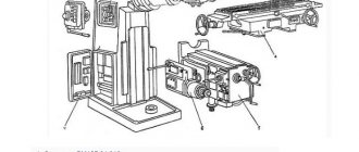
Surface grinding machine
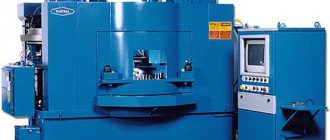
Surface grinding machines (Fig. 4) are designed for processing flat surfaces of parts using an abrasive tool, usually a grinding wheel.
Figure 4. Surface grinding machine.
Figure 4. Surface grinding machine.
Structurally, a surface grinding machine consists of a frame on which a table is mounted. The workpiece is fixed in it. A support is installed on the frame. Depending on the degree of mobility of the elements, surface grinding machines are divided into three subgroups:
- with a movable table;
- with movable support;
- with movable table and support.
The support has a grinding head in which the abrasive wheel is fixed. The circle is driven by an electric motor. To change the rotation speed there is a gearbox.
Grinding is carried out by reciprocating movements of the workpiece relative to the abrasive wheel or with a constant feed in one direction until the pass is completed.
Classification
Modern internal grinding machines are mainly divided into several types. They are structurally similar to vertical and horizontal or milling installations. But the difference may lie in the choice of the method of processing parts, while the spindle is located in the workpiece, removing excess material from the workpiece, using the rotation method.
Often the workpiece may remain stationary. In this case, the rotation coming from the main drive is transmitted to the spindle head shaft. Afterwards, various types of grinding tools are installed on it. The choice of tools directly depends on the level of processing and the material from which the part is made. To process large-sized products, special models of machines are used that are designed for significantly high loads.
Main components of an internal grinding machine
Any internal grinding machine has the following components:
- headstock of the product;
In turn, the grandmother is divided into:
a) the headstock of the internal grinding machine. It provides both transverse and circular feed of the part. The front headstock support is a double-row roller bearing with a cone-shaped hole. The rear headstock support often consists of a pair of duplexed angular contact bearings. Also, the spindle assembly can be provided with several long spacer bushings with tightening and independent adjustment of the tension in the bearings, secured with separate nuts. The spindle drive is always carried out by overdrive flat toothed belts.
b) Tailstock, which has only adjustment movement, in order to be adjusted to a given machining length. This headstock has a quill into which the rear center is inserted. The quill can be moved by clamping and releasing the part.
- grinding head:
As a rule, the grinding head is one of the main components of the machine. It consists of a grinding wheel spindle with supports and a drive to it,
and hulls;
- table:
The table, placed along the guides, carries a grinding headstock;
- hydraulic table drive;
- bed.
Often, a headstock is installed on the bed, which is rigidly fixed and remains motionless.
Purpose of the 3K228A internal grinding machine
The 3K228A universal cylindrical grinding machine is produced by a Russian machine tool manufacturer and is used for processing cylindrical and conical holes in parts of rotating bodies such as bushings and disks by grinding. The machines of this series can process the holes of gears (smooth and splined), inner rings of ball bearings and roller bearings; roller tracks of the outer rings of roller bearings; holes of conductor bushings, adapter bushings with a Morse taper, various cutting tools, such as milling cutters, attachment reamers, etc.
A significant advantage of universal internal grinding machines such as 3K228A is that they can grind through and blind holes in materials of various hardness and structure - unhardened and hardened steel, cast iron, non-ferrous metals and alloys, as well as non-metallic materials.
Another advantage of this equipment is that, using the internal grinding operation on 3K228A machines, it is possible to correct the deviation (displacement) of the hole axis resulting from previous workpiece processing operations.
We offer to buy an internal grinding machine 3K228A at the price of the manufacturer.
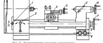
Internal grinder controls
The main controls of the internal grinding machine are:
- flywheel for changing the spindle speed;
- flywheel for manual transverse movement of the grinding head;
- fungus for turning on the fine radial periodic feed of the grinding wheel;
- flywheel for manual longitudinal movement of the table;
- handle for turning on the hydraulic drive of the table;
- handles for changing table speed;
- lever for retracting the table to the non-working position;
- push-button station;
- square for transverse movement of the headstock of the product;
- square for turning the headstock of the product;
- handle for hydraulic clamping of the product.
Accessories for internal grinding machine 3A228
Face grinding device
The machine can be equipped with an end grinding device that allows you to grind the end of the part with a special wheel. The spindle of this device rotates from an individual electric motor 1 through a V-belt transmission 3-15. The adjustment longitudinal movement of the grinding wheel is achieved by rotating the flywheel 7. The working (axial) feed is produced by rotating the flywheel 14, while the sleeve of the end spindle carrying the wheel moves longitudinally through the worm pair 11-13 and the screw pair 12. The trunk 9 has three positions and is rotated by a hydraulic drive from the upper non-working position to the lower working position and back using the piston-rack 8 and the gear sector 2. The trunk is turned to the position of wheel editing (intermediate between the working and non-working positions) by the piston 10 through the same rack and sector.
Mechanism of oscillatory motion of the table
As a device, the machine is equipped with a mechanism for the oscillatory movement of the table, which, imparting longitudinal oscillatory movements to it, forces the grinding wheel to perform oscillating movements, which contribute to obtaining a less rough sanded surface. The mechanism has an individual electric motor 54, from which an adjustable eccentric 51 is driven through a worm pair 53-52. From it, a lever 50 comes into oscillatory motion, which, in turn, acts through a stop 49 on the table, pressed against it by a hydraulic cylinder.
Movements in an internal grinding machine
The cutting movement of this machine is the rotation of the spindle associated with the grinding head combined with an abrasive wheel. The pair consisting of the spindle of the headstock of the product and the part is given a circular feed. Longitudinal feed is the reciprocating rectilinear movement of the table with the grinding headstock. Transverse feed is the periodic movement of the grinding head in the radial direction during the table stroke. Auxiliary movements may include movements of the workpiece headstock, manual movements of the table and grinding headstock.
Operating principle of internal grinding machine
In an internal grinding machine, the workpiece is fixed in a membrane or three-jaw chuck using a hydraulic clamp, the cylinder of which rotates with it, located at the left end of the spindle.
The release of the processed part is carried out by a special pilot. This release can only be reproduced with the extreme right non-working position of the machine table. The spindle of the product headstock is rotated, which corresponds to the selected circular feed speed. The grinding wheel, which is mounted on the spindle of the grinding headstock, can rotate at the highest speeds that correspond to the selected cutting speed.
When grinding a cylindrical hole, the spindle axis of the workpiece headstock is located parallel to the table guides. When grinding a conical hole, the workpiece headstock is installed in such a position that the spindle axis creates an angle with the table guides that is equal to half the angle of the hole cone. The headstock of the product rotates about its vertical axis in the form of a square.
The automatic operating cycle of an internal grinding machine is as follows. First, the processing of parts occurs in a rough grinding operation. After the rough grinding allowance has been removed at the command of the electrical measuring device, the table is moved to the extreme right position. After this, the grinding wheel is dressed. The slow speed of the table that occurs during straightening is set by a special throttle.
After finishing the wheel dressing, the automation panel switches the machine to the pure grinding mode. After finishing grinding, the measuring device sends a command to turn off the periodic cross feed and turns on a time relay, which can control the drying process. After the end of nursing, in a short time the table is moved to the right and stops. At this time, it is possible to release the hydraulic clamp of the part, then the hydraulic system is prepared to switch to the rough grinding mode of the next part.
CNC INTERNAL GRINDING MACHINE PALMARY OIG-150
Devices for fastening gears
- This device is specially designed for quick and convenient gear changes.
- Three-point gear clamping.
Wheelhead guides
- It is possible to select automatic or manual feeding mode.
- Editing characteristics are set using the user interface. The minimum step is 0.001 mm.
- The position of the correct device can be memorized in the PLC.
Automatic belt tension adjustment
- Belt tension is automatically controlled by the weight of the motor to maintain good rotation at all times and prevent belt loosening, which could affect sanding quality.
Machine design features
- OIG series CNC internal grinding machines are designed entirely for ease of operation.
- The machine bed is cast from high-quality Mikhanit cast iron, heat-treated, internal stresses are removed before machining.
- The three-axis CNC internal grinding machine has controlled X, Y and Z axes, 2 grinding spindles, the machine can grind holes, ends and external surfaces in one installation, which is necessary for parts with very high alignment tolerances.
- It is possible to grind cylinder bore, end face, inner corner chamfer, groove, inner cone, inner stepped hole, etc.
- To achieve mass production productivity, it is possible to add automatic part loading and unloading as options to ensure complete automation of the process.
- All guides are automatically lubricated by a lubrication system, thus ensuring extremely smooth movement and high wear resistance.
- The combination of grinding spindles and the use of large grinding wheels allows machining of the outer diameter or face. A large number of special functions are available according to customer requirements.
- All axes work so that many kinds of main and auxiliary processes occur in one cycle automatically, thus reducing piece time.
- Programs are entered into a teach-in mode, which allows the operator to fill in certain program parameters into a table to set different grinding modes. This mode also supports automatic wheel editing and correction to increase productivity.
- Linear feed axes are equipped with optical rulers to increase positioning accuracy.
- The use of a sound frequency sensor and a current control sensor provides the necessary sequence of operations. This also helps to avoid collisions between the workpiece and machine components due to erroneous movements in the control program.
- It is possible to install a large number of devices for fastening parts on the working spindle.
- The electrical cabinet is assembled from high-quality electrical components, providing excellent control of the work process and durability of the electrical equipment.
- The electrical cabinet is equipped with a heat exchanger that maintains a constant temperature of the control circuit and maximum stability of control characteristics
- The electrical cabinet is reliably dust and moisture protected.
Electrical cabinet
CNC system
- Improved usability
- Color graphic display
- Easy program editing
- Complete software package
- Easy to integrate other functions
Main functions of the CNC system
- Capacity – 160 MB
- Program registration
- Search by number
- Program protection
- Background editing of CP
- Bilingual display: English-Russian
- Display of spindle speed, T-codes, number of parts
- Time display
- Display of current grinding speed
- Entering Foreign Keys
- External messages
- I/O device monitoring
- MDI (manually entered program)
- Idle run
- Simple blocks
- Emergency stop
- Status Screen
- Setting the Incremental Rhythm
- Automatic coordinate adjustment
- Setting workpiece coordinates
- Simultaneous Z coordinate adjustment
- Smallest input increment – 0.001 mm
- Smallest command increment – 0.001 mm
- Accelerated longitudinal correction – 0, 25, 50, 100
- Automatic acceleration/deceleration
- Feed Interpolation
- Feed correction from 0 to 150%
- Linear interpolation
- Circular interpolation
- Return to zero point
- Zero point monitoring
- Combination of programs
- Special G-code input
- Programmable manual override data input
- Macro B programming language
- Metric/Inch system
- Tool radius compensation
- Repeat cycle of previous operation
- X Axis Radius/Diameter Command
- Correction value counter input
- Radius symbol on an arc
- External data input/output
- Manual feed by handwheel
- Manual feed speed adjustment
- Stop
- Function of fast skipping part of the program
- External deceleration
- Position signal output
- Low battery alarm
- Gap compensation
- Automatic EIA/ISO code recognition
- Multi-step skip
- Various functions
- 9-inch high resolution CRT display
- Monochrome screen
- Uninstall function
- Program copy function
- Self-diagnosis function
- Memory for 32 tool offset pairs
- Correction of the correct tool
- Tool geometry / wear compensation
- Easy tool life control
- Client macros
Properties of internal grinding machines.
1.The internal grinding machine is equipped with a feeding system and a compensation straightening system. They are two independent systems. After changing a new wheel there is no need to adjust the machine. A single processing cycle to control the final size of the workpiece.
2.The internal grinding machine is equipped with a jumping device, so there is no need for manual re-installation after measuring or straightening.
3. The work table is equipped with an axial micro-motion device to process the end surface with an internal grinding spindle. It is driven by hydraulics. Stepless speed control. There is a manual or hydraulic feed of the grinding wheel. The thyristor converter changes the spindle speed. The bed of the internal grinding machine has a machined surface for installing a steady rest to grind long workpieces.
4.The internal grinding machine is equipped with end surface grinding application. The rotating speed of the grinding spindle is 18000r/min. The largest internal diameter of the sanded product can reach 20mm.
List of main technical characteristics of internal grinding machines
Almost all models and types of internal grinding machines can be designed for processing metal products. Similar operations for processing wooden blanks are reproduced using other types of equipment. Therefore, the technical characteristics of internal grinding machines can only be calculated for processing large-sized products with the largest dimensions.
So, firstly, the maximum and minimum dimensions of the workpieces are determined. This can be attributed to the internal diameter of the hole, as well as the external dimensions of the workpiece. Next, you need to calculate the maximum permissible mass of the part. Secondly, you need to select the processing degree parameter from the following: end, internal or double-sided. Based on the above data, it is necessary to select the optimal model of an internal grinding machine.
Additionally, it is recommended to familiarize yourself with the following technical characteristics of the internal grinding machine equipment:
1.Maximum length of workpiece grinding.
v The grinding length may depend on the diameter of the workpiece. Often, the manufacturer indicates this parameter for maximum and minimum diameters;
2. Processing of cones.
v It is imperative to know:
- Allowable cone angle;
- Distance from the spindle axis to the worktable surface;
- The greatest distance from the end of the workpiece to the support cylinder of the spindle head;
- Electric motor power.
In most cases, this only applies to the drive of the main movement of the spindle head.
v The power of the coolant system and the lubricating element of the machine is taken into account;
3.Dimensions and weight of equipment:
For overall characteristics, it is imperative to know all the dimensions of the support platform and the dimensions with possible additional equipment;
4. An indicator of the accuracy of workpiece processing and the roughness of the prepared surface.
v Based on these indicators, it is necessary to select the most optimal equipment option. Also, it should be taken into account that for processing large-sized products you will need special installations that are necessary for installing the fastening block. This condition is mandatory only when the mass of the workpiece significantly exceeds 20 kilograms.
The detailed technical characteristics of the internal grinding machine can be viewed on the RIG-150СNC model, since this machine is in demand:
- Maximum Grinding Hole Diameter (mm) – 6~150;
- Maximum Length of Grinding Hole (mm.) – 150;
- Diameter of processing over the bed (mm.) –520;
- Processing Diameter with Installed Chuck Protection (mm.) –320;
- Maximum Table Movement (mm.) –540;
- Table Movement Speed (m./min.) – 27
- Speed of movement of the hydraulic table (m/min) – 7.2;
- Speed of movement of the hydraulic table along one of the axes (m/min) – 20;
- Spindle Rotation Speed (rpm) – 0~800;
- Working Feed Speed of the Spindle Head (mm./min.) – 50;
- Accelerated Movement along the X Axis (m/min.) – 6;
- Minimum Step Value along the X Axis (mm) – 0.001;
- Minimum Step Value along the Z Axis (mm) – 0.001;
- Headstock Rotation Angle (degrees) Right – 13°;
- Headstock Rotation Angle (degrees) Left – 5°;
- Distance from the Spindle Center to the Floor (mm.) – 1060;
- Adjustable Grinding Spindle Length (mm.) – 100;
- Feed: Automatic hydraulic, stepless, automatic, servomotor;
- Headstock Motor Power (kW) – 0.75;
- Power of the Servomotor for Feeding the Spindle Head (W) – 400;
- Grinding Head Motor Power (kW) – 1.5;
- Hydraulic Pump Power (kW): First axis – 1.5 / Second axis – 0.75;
- Coolant Pump Power (kW) – 0.09375;
- X-Axis Servomotor Power (kW): First axis – 0.6 / Second axis – 0.9;
- Power of the Z-Axis Servomotor (kW) – 2;
- Hydraulic Tank Capacity (liter) – 90;
- Coolant tank capacity (liter) – 80;
- Area (mm.) – 2600 x 1430;
- Machine height (mm.) – 1400;
- Machine weight (kg) –2600.
Technical characteristics of the machine 3K228A
| Parameter name | 3K228A | 3K229A |
| Main settings | ||
| Accuracy class according to GOST 8-82 | A | A |
| Largest diameter of the installed product, mm | 400 | 800 |
| The largest diameter of the installed product in the casing, mm | 400 | 630 |
| Maximum length of the installed product, mm | 320 | 500 |
| Smallest and largest diameter of the hole to be ground, mm | 50..300 | 100..500 |
| The longest grinding length with a grinding diameter of at least 100 mm, mm | 320 | 500 |
| Maximum recommended grinding length at smallest diameter, mm | 125 | 200 |
| Distance from the axis of the headstock spindle to the base of the bed, mm | 1225 | 1300 |
| Distance from the axis of the headstock spindle to the table mirror (height of centers), mm | 340 | 410 |
| Distance from the supporting end of the product spindle flange to the end of the grinding headstock bracket, mm | 1335 | 1570 |
| Distance from the end of the new face grinding wheel to the supporting end of the spindle flange, mm | 150..400 | 250..550 |
| Machine work table | ||
| Maximum table movement length, mm | 800 | 800 |
| Manual movement of the table per revolution of the flywheel, mm | 25 | 25 |
| Table movement speed when grinding, m/min | 1..7 | 1..7 |
| Table movement speed when editing a wheel, m/min | 0,1..2 | 0,1..2 |
| Table movement speed with rapid longitudinal approach and retraction, m/min | 10 | 10 |
| Face grinding device | ||
| Face spindle rotation speed, 1/min | 4000 | 4000 |
| Longitudinal movement of the end grinding wheel is maximum adjustment, mm | 250 | 250 |
| Longitudinal movement of the end grinding wheel is greatest working (fine), mm | 4 | 4 |
| Longitudinal movement of the face grinding wheel per revolution of the adjustment movement handwheel, mm | 27 | 27 |
| Longitudinal movement of the end grinding wheel per revolution of the working (fine) feed handwheel, mm | 0,1 | 0,1 |
| Longitudinal movement of the end grinding wheel per division of the working (fine) feed dial, mm | 0,0025 | 0,0025 |
| Grinding head | ||
| Rotation speed of internal grinding heads, 1/min | 4500,5300,8200,12000 | 2500,4500,5250,8200 |
| The largest diameter of the grinding wheel according to GOST 2424-83, mm | 200 x 76 x 63 | 250 x 76 x 63 |
| Maximum peripheral speed of the grinding wheel, m/s | 35 | 35 |
| Diameter of the internal grinding head sleeve, mm | 125 | 125 |
| Diameter of the end of the grinding spindle according to GOST 2324-77, mm | 30, 40, 50 | At least 45 |
| Transverse movement of the grinding head | ||
| Movement per one revolution of the handwheel - rough (adjustment), mm | 5 | 5 |
| Movement per revolution of the handwheel - fine, mm | 0,5 | 0,5 |
| Movement by one division of the dial, mm | 0,002 | 0,002 |
| Movement per swing of the manual dosed feed lever, mm | 0,002 | 0,002 |
| The largest adjustment movement of the grinding head is backward (to the worker), mm | 10 | 10 |
| The largest adjustment movement of the grinding head is forward (from the worker), mm | 80 | 100 |
| Headstock (product headstock) | ||
| Nominal diameter of the end of the spindle of the product, according to GOST 12595-72 | 2-8M | 2-11M |
| Maximum angle of rotation of the headstock of the product, degrees | 30 | 30 |
| The largest adjustment movement of the headstock of the product is backward (to the worker), deg | 50 | 50 |
| The largest adjustment movement of the headstock of the product is forward (from the worker), deg | 250 | 300 |
| Product rotation speed (stepless regulation), rpm | 60..600 | 20..240 |
| Drive and electrical equipment of the machine | ||
| Number of electric motors on the machine | 7 | 7 |
| Grinding head spindle electric motor, kW | 7,5 | 7,5 |
| Electric motor drive of the face grinding device, kW | 2,2 | 2,2 |
| Electric motor of the product drive (product headstock) DC, kW | 1,6 | 1,6 |
| Hydraulic pump electric motor, kW | 3,0 | 3,0 |
| Electric motor of the filter-conveyor, kW | 0,09 | 0,09 |
| Electric motor of the cooling system pump, kW | 0,15 | 0,15 |
| Magnetic separator electric motor, kW | 0,09 | 0,09 |
| Total power of electric motors, kW | 14,63 | 14,63 |
| Thyristor converter ET1E2-10, kW | 1,3 | 1,3 |
| Overall dimensions and weight of the machine | ||
| Overall dimensions of the machine (length x width x height), mm | 3535 x 1460 x 1870 | 4165 x 1780 x 2000 |
| Weight of the machine with electrical equipment and cooling, kg | 6400 | 8300 |
- Universal internal grinding machines of especially high precision 3K228A, 3K229A. Manual for machines
- Alperovich T.A., Konstantinov K.N., Shapiro A.Ya. Design of grinding machines, 1989
- Alperovich T.A., Konstantinov K.N., Shapiro A.Ya. Setup and operation of grinding machines, 1989
- Dibner L.G., Tsofin E.E. Sharpening machines and semi-automatic machines, 1978
- Genis B.M., Doctor L.Sh., Tergan V.S. Grinding on cylindrical grinding machines, 1965
- Kashchuk V.A., Vereshchagin A.B. Grinder's Handbook, 1988
- Kulikov S.I. Honing, 1973
- Lisova A.I. Design, adjustment and operation of metal-cutting machines, 1971
- Loskutov V.V. Metal grinding, 1985
- Loskutov V.V. Grinding machines, 1988
- Lurie G.B. Grinding machines and their adjustment, 1972
- Lurie G.B. Design of grinding machines, 1983
- Menitsky I.D. Universal sharpening machines, 1968
- Mutsyanko V.I. Bratchikov A.Ya. Centerless grinding, 1986
- Naerman M.S., Naerman Ya.M. Guide for training grinders. Textbook for vocational schools, 1989
- Naerman E.S. The Young Grinder's Handbook, 1991.
- Popov S.A. Grinding work, 1987
- Tergan V.S. Grinding on cylindrical grinding machines, 1972
- Shamov B.P. Types and designs of main components of grinding machines, 1965
Bibliography:
Related Links. Additional Information
- Classification and main characteristics of the grinding group
- Repair, restoration and modernization of grinding machines: the American approach
- Cylindrical grinding. Processing on cylindrical grinding machines. Grinding Methods
- Setting up a cylindrical grinding machine when installing parts in centers
- CNC grinding machines
- Marking of grinding wheels
- Testing and checking metal-cutting machines for accuracy
- Grinding machines. Market of grinding machines in Russia
- Manufacturers of sharpening and grinding machines in Russia
- Directory of grinding machines
Home About the company News Articles Price list Contacts Reference information Interesting video KPO woodworking machines Manufacturers
Setting up internal grinding machines
Significant stages in each machine are mastering the manual for the operation of this machine, safety measures when handling the machine, working on it, as well as monitoring the operation of absolutely all controls and locking devices of this machine. Before starting to work on the machine, it is necessary to lubricate all the required parts of the machine in accordance with the lubrication frequency schedule, and also check the suitability of the coolant and the condition of the machine controls. As a rule, the setup of machines begins by checking the location of the headstock of the product.
First of all, you need to install the first part, then grind all the necessary working jaws, installing them at a distance that becomes equal to the outer diameter of the surface of the clamped part, taken by the base. In addition, it is necessary to grind the surface of the faceplate using a cup-type wheel or a G1B-shaped wheel. The size of the circle is used in accordance with the diameter of the hole of the part that will be processed, and the properties of the circle are selected in connection with the required surface qualities and accuracy of the hole, established by the drawings of the part.
After securing the workpiece in the chuck, it is necessary to install the table stops so that when the table moves to the right and left, the exit of the grinding wheel from the workpiece is equal to 1/3-1/2 of its width. When setting up to process parts of different shapes and lengths, it may be necessary to move the grinding head along the table. To do this, it is necessary to connect the headstock to the bridge with a special bar and the flywheel of the manual table movement mechanism moves the table relative to the headstock.
To ensure safe operation of the machine, it is necessary to install the sliding protective cover of the product so that it completely covers the part. For each grinding wheel it is necessary to select the appropriate replacement guard.
First, the dressing mechanism is adjusted in the longitudinal direction, placing the diamond from the end of the part at a distance equal to the width of the circle plus 15-20 mm. In the transverse direction, the top of the diamond is set along the generatrix of the grinding wheel when it touches the surface of the hole being processed. The top of the diamond must lie in a plane passing through the axes of the grinding wheel and the hole being processed. This is achieved by adjusting the diamond holder stop.
In order to make the first wheel edit, you must perform the following steps:
- Turn on the machine (the signal light should light up);
- Move the table to the extreme right position;
- Turn on the electric motor of the hydraulic system and together with it the coolant pump;
- Insert the grinding wheel into the grinding zone by turning the “START” handle and reversing the table;
- Check the table stroke length when grinding;
- Use to adjust the speed of table movement;
- By turning the reverse handle to the right, bring the wheel into the straightening zone, checking that the length of the table stroke is correct when straightening;
- Use the throttle to adjust the speed of the table when editing;
- Turn on the rotation of the internal grinding spindle;
- Set the cross feed mechanism handle to the “Slow movement” position.
- Correct in several strokes using the cross-feed flywheel.
Information about the manufacturer of the 3K228V internal grinding machine
Machine tools produced by the Voronezh Machine Tool Plant
Features of internal grinding
Internal grinding is one of the main methods for finishing holes, in which, depending on the grinding modes and characteristics of the grinding wheel, machining accuracy of 1-3 classes and surface roughness V7-V9 can be achieved.
The advantage of the internal grinding process is the ability to correct the misalignment of the hole axis formed in previous operations, as well as ensuring the perpendicularity of the end surface to the hole axis, which is achieved when grinding the hole and end from one setting.
Internal grinding can be used to machine cylindrical and conical through and blind holes in parts made of non-hardened and hardened steel, cast iron, non-ferrous metals and non-metallic materials.
Internal grinding is widely used in all branches of mechanical engineering. Internal grinding machines process the holes of gears (smooth and splined), inner rings of ball bearings and roller bearings; roller tracks of the outer rings of roller bearings; holes of conductor bushings, adapter bushings with a Morse taper, various cutting tools, such as cutters, shaver, attachment reamers, etc.
In internal grinding, both grinding with longitudinal feed and the plunge method are used. The first method is most widespread. Plunge grinding is used when grinding short holes, as well as holes limited by shoulders or ledges.
For internal grinding, longitudinal and transverse feed methods are used. The following types of movements are distinguished:
- rotation of the grinding wheel at a speed specified in m/sec
- rotation of the part (circular feed) at a speed specified in m/min
- longitudinal feed, specified in fractions of the wheel height and transverse feed in mm/double stroke or mm/min
When grinding with longitudinal feed, the feed rate should not exceed 3/4 of the wheel height per revolution of the part. The cross feed is intermittent for each single or double stroke or continuous.
Plunge grinding is used when processing short holes, as well as internal cylindrical surfaces limited by precise ends or steps, for example, roller tracks of bearing rings. To ensure uniform wear, the circle is given additional oscillating motion if the configuration of the part allows it.
The features of internal grinding create a number of limitations for the use of this method. These include:
- dependence of the diameter of the grinding wheel on the diameter of the grinding hole of the part
- the need to insert the wheel into the hole, which requires a significant overhang of the spindle carrying the grinding wheel, especially when grinding long holes. This leads to a decrease in system rigidity and limits the use of performance modes.
The dependence of the diameter of the grinding wheel on the diameter of the grinding hole, as well as the need for a significant overhang of the grinding spindle, especially when grinding long holes, caused by the insertion of the grinding wheel into the hole being processed, leads to a decrease in the rigidity of the system and creates a number of restrictions for the use of internal grinding.
Design of internal grinding machines
Internal grinding machines can be divided into two main groups.
- Machines in which the workpiece and grinding wheel rotate, and longitudinal and transverse feeds are carried out by moving the grinding spindle or headstock. Depending on the method of basing the workpiece, these machines can be cartridge or centerless. In Fig. 85 shows various basing schemes. In Fig. 85, a, b, c show cartridge methods for installing parts, respectively, with basing in a membrane cartridge (c), in a cartridge at the ends (b), in a sleeve along the outer diameter with a clamp at the ends (c). In Fig. 85, d, e show centerless methods of basing on shoes (d) and on rollers (e).
- Machines in which the workpiece, usually large in size and weight, is mounted motionless on the machine table, and the grinding wheel carries out planetary motion, rotating simultaneously around its axis and around the axis of the hole. Longitudinal and transverse feeds are carried out by moving the grinding wheel along arrows 3 and 4, respectively. Such machines are called “planetary”, they can be either with a vertical or horizontal spindle and have very limited use.
Depending on the nature of production, universal internal grinding machines, semi-automatic and automatic machines are used.
Universal machines with chuck clamping are used for processing short and long cylindrical and conical holes. Tapered holes are ground by turning the headstock to the appropriate angle. These machines are common in auxiliary workshops of mass production factories, as well as in the main workshops of mass production factories. Universal machines are usually equipped with a face grinding device, which makes it possible to ensure high precision in the processing of the perpendicularity of the end to the hole. Grinding heads on universal machines are mounted on a slide and can be replaceable.
Semi-automatic machines , widely used in mass and large-scale production, are equipped with measuring and control devices that automatically control the grinding process and stop processing when the specified size is reached.
Automatic machines - center and centerless - are additionally equipped with loading devices that supply parts to be processed into the grinding zone, as well as devices for automatically securing and removing parts and controlling wheel dressing.
The main internal grinding machines produced by the domestic industry are machines of the ZK range. These machines are designed for processing holes with a diameter of 3 to 800 mm and are produced in accuracy classes P, B and A. All universal machines of the ZK range, with the exception of the ZK230V model, are equipped with face grinding devices.
Based on the basic models, various modifications of machines are produced - with an extended table stroke for processing long parts.
Features of operation of internal grinding machines
As a rule, the operation of any metalworking equipment begins with choosing the correct installation plan for the machine. First, you need to prepare a site for installation, taking into account the weight and dimensions of the machine. Also, it is additionally necessary to take into account the impact on the slab in the form of vibrations that occur during operation.
Next, you should calculate all the necessary parameters of the connected electrical network. To do this, you need to know the maximum power consumption of the machine. Based on these values, electrical wiring with the appropriate cross-section is selected. An RCD and ground loop must be installed.
When carrying out work on an internal grinding machine, you must adhere to the following rules:
1.Preparation of equipment.
- After a long period of inactivity, it is necessary to inspect all components and assemblies. The machine starts only in idle mode and without installing a workpiece. The correct operation of the lubricating and cooling system and chip removal must be checked;
2.Staff.
- Before starting work on the machine, personnel are required to undergo a training course, which includes studying the design of the machine, as well as familiarization with the rules of operation of the machine and safety precautions;