The name of the semiconductor element, similar to a diode, speaks for itself. It allows you to stabilize already smoothed tension due to its physical characteristics. Often there is such a need as checking the zener diode. It is necessary to find out the serviceability of a part when voltage stabilization in the circuit where it is installed is not ensured.
Appearance of the zener diode
What is a zener diode
Almost no voltage stabilizer can do without this semiconductor. In appearance it can easily be confused with a diode. You can find out which element stabilizes the potential difference by marking. A Zener diode (zener diode) has high resistance until breakdown occurs. The applied reverse bias causes a breakdown of the junction, and the current begins to rapidly increase, and the resistance decreases in the range from hundreds of Ohms to its fractional values. This mode of operation makes it possible to maintain a constant voltage value on the element with a certain accuracy.
The main task of a semiconductor is to stabilize the voltage. They produce parts in series that are designed to maintain 1.8-400 V. The radio component is included in the circuit in parallel with the load.
Conventional graphic designation of an element
Attention! A two-terminal network has conclusions: a cathode and an anode. If we consider the region of the pn junction, then the terminal connected to the p-region is the anode, and to the n-region is the cathode.
Semiconductor elements that are composed of two counter-directed zener diodes are called double-sided (two-node).
Double-sided zener diode
The classification of these two-terminal networks according to their functional purpose is as follows:
- parts for general use (discrete), power: 0-0.3; 0.3-5; 5-10 W and above;
- precision elements with a complex microcircuit in their structure (hidden structure);
- limiting zener diodes designed for interference suppressors.
The latter are designed for short-term transmission of pulsed current up to hundreds of amperes. Long-term operation with high currents causes overheating of the part and thermal breakdown.
Attention! A silicon diode (zener diode) connected to the circuit in the reverse direction has three types of breakdown: tunnel, avalanche, and caused by thermal instability. Their design implies the occurrence of the first two breakdowns before thermal destruction of the junction occurs.
Switching circuit and current-voltage characteristic (volt-ampere characteristic) Zener diode
Checking the photodiode
In a simple test, the reverse and forward resistance of a radio element placed under a light source is measured, after which it is darkened and the procedure is repeated. For more accurate testing, you will need to take the current-voltage characteristic; this can be done using a simple circuit.
An example of a circuit for measuring current-voltage characteristics
To illuminate the photodiode during testing, you can use an incandescent lamp with a power of 60 W or more as a light source or bring the radio component to a chandelier.
Photodiodes sometimes have a characteristic defect, which manifests itself in the form of a chaotic change in current. To detect such a malfunction, it is necessary to connect the element under test as shown in the figure and measure the reverse current for a couple of minutes.
Testing for "creep"
If during testing the current level remains unchanged, then the photodiode can be considered working.
Testing without desoldering.
As practice shows, it is not always possible to test a diode without desoldering it when it is on the board, like other radio components (for example, a transistor, capacitor, thyristor, etc.). This is due to the fact that elements in the circuit may produce an error. Therefore, before checking the diode, it must be desoldered.
Externally, a zener diode is similar to a diode and is available in glass and metal housings. Its main property is to maintain a constant voltage at its terminals when a certain potential is reached. This is observed when the tunnel breakdown voltage is reached.
Conventional diodes with such values quickly reach thermal breakdown and burn out. Zener diodes, also called Zener diodes, can be in tunnel or avalanche breakdown mode constantly, without harm to themselves, without reaching thermal breakdown. The device is made of monocrystalline silicon and acts as a stabilizer or reference voltage in electronic equipment. High-voltage surge protectors, integrated zener diodes with a hidden structure are used as a reference voltage in analog-to-digital converters.
Read also: What gas is used to fill cylinders for a gas stove?
Check procedure
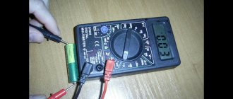
The test is carried out with a conventional tester, switching the device to the range for measuring diodes or resistance.
Connecting a multimeter for testing
How to test a resistor with a multimeter
The element-by-element description of the check looks like:
- the resistance measurement mode is selected on the device;
- the tester probes are connected to the pins of the part;
- The instrument readings displayed on the display are evaluated.
When the multimeter’s own power supply is connected with a positive probe to the anode, the display can record resistance readings from a few fractions of an ohm to its units. After replacing the measuring probes with a working element, an infinitely large resistance is obtained.
Keeping in mind that the zener diode behaves like a simple diode, set the measurement interval in kOhms. In this case, the resistance of a working radio component reaches hundreds of kOhms.
Information. The readings displayed on the display by the tester often mislead the person conducting the measurement.
The same high resistance with different probe connections does not always mean a breakdown of the element. The internal source voltage supplied for measurements may exceed the rated breakdown voltage, then the results obtained will be false.
How to check a zener diode with a multimeter on a board
How to check battery capacity with a multimeter
When it is not possible to free both terminals of an element for measurements, how to check the zener diodes? It is advisable to unsolder at least one of the legs (leads) of the semiconductor device. In this way, break the circuit circuit on the board where the semiconductor is soldered. This will avoid distortion of readings during measurements. Inaccuracy may arise from the influence of other elements included in the circuit. In addition, you need to de-energize the board on which the element being tested is located.
Is it possible to check the part without desoldering?
Zener diode TL431
Soldering a semiconductor part is not always convenient, especially if the boards have double-sided circuit mounting. Checking zener diodes with a multimeter without dismantling is quite possible. If the readings of the measuring device do not indicate damage, then they can be considered real. If the results show a break, you can be sure that this is also a fact. But when measurements register a breakdown - low resistance with any polarity of connecting the probes, this is not always the case. In this case, the part must be desoldered.
Carefully. Measurements with a tester with an internal voltage greater than the breakdown voltage of the zener diode can lead to a real breakdown. To check such elements, it is convenient to use pointer analog instruments. Their supply voltage is no more than 3 V.
Analog pointer tester
Scheme to check
Let's consider another simple circuit for determining the stabilization voltage, which consists of:
- Regulated power supply. The DC voltage should vary smoothly with a potentiometer from 0 to 50 V (the higher the maximum voltage, the larger the range of elements you can test). This will allow you to test almost any low-power zener diode.
- Set of current limiting resistors. They usually come in denominations of 1 Kom, 2.2 Kom and 4.7 Kom, but there can be more. It all depends on the voltage and current stabilization.
- Voltmeter, you can use an ordinary multimeter.
- Block with spring-loaded contacts. It must have several cells to be able to connect semiconductors with different packages.
To check, connect a zener diode according to the above diagram and gradually increase the voltage at the power source from 0. At the same time, monitor the voltmeter readings. As soon as the voltage on the element stops increasing, regardless of its increase on the power supply, this will be voltage stabilization.
If there is a marking on the element, then the data obtained during measurement is checked against the table in the parameter reference book.
Note that zener diodes can be produced in various designs. For example, KS162 are produced in ceramic cases, KS133 in glass, D814 and D818 in metal.
Here are the characteristics of some common domestic zener diodes:
- KS133a stabilization voltage is 3.3 V, produced in a glass case;
- KS147a maintains voltage at 4.7 V, glass case;
- KS162a – 6.2 V, ceramic body;
- KS175a – 7.5 V, has a ceramic body;
- KS433a – 3.3 V, produced in a metal case;
- KS515a – 15 V, metal housing;
- KS524g – in a ceramic case with a voltage of 24 V;
- KS531v – 31 V, ceramic case;
- KS210b – stabilization voltage 10 V, ceramic body;
- D814a – 7-8.5 V, in a metal case;
- D818b – 9 V, metal case;
- D817b - 68 V, in a metal housing.
To test a zener diode with high stabilization voltages, another circuit is used, which is shown in the figure below.
The check is carried out in the same way as described. Similar devices are produced by Chinese manufacturers.
However, you can assemble a simple circuit for testing zener diodes using a multimeter. This is clearly shown in the video below.
It should be warned that the electrical circuit shown in the video is not recommended for use, because it is unsafe and requires compliance with safety precautions. Otherwise, you may get injured (at best).
How to test double-sided zener diode
It happens that after desoldering a semiconductor element from the board, when changing the polarity on the probes, the resistance turns out to be high in both cases. This does not necessarily indicate a break. The circuit component under test may be a double-ended zener diode. How to check a zener diode with a multimeter?
To test its performance, you need to:
- increase the applied measurement voltage;
- change the polarity supplied by the tester probes to the terminals;
- measure currents and compare the current-voltage characteristics of the part under study.
A set of actions will help determine whether such a zener diode is working or not. Knowing that in such a radio component the cathodes are internally connected to each other, it is necessary to assemble a circuit.
The circuit includes the following components:
- tester;
- resistor with a resistance of 1 kOhm (R);
- IP up to 30 volts.
To measure, everything is connected together into a circuit:
- connect the resistor to the “+” power source;
- The zener diode is connected to the second contact of the resistor;
- the tester probe is connected to the free terminal R and the “-” terminal IP;
- the device is connected to the gap: “+” IP and “-” IP;
- The most suitable mode is selected on the device.
When checking a zener diode with a stabilization voltage, the circuit will be working if, by changing Upit within 13-30 V, the device display remains within 12 V, even when changing polarity.
Important! No measuring device can guarantee that the results obtained are truly correct. To check, you need to connect a semiconductor to the circuit, apply power and take measurements that identify the faulty part.
General information about the operating principle
If you do not know how a zener diode works, then before reading the current article, read the previously published one -.
When a certain voltage is reached, an avalanche-like breakdown of the pn junction occurs. The junction resistance decreases. As a result, the voltage across the diode remains constant. And the current flowing through the semiconductor increases.
The principle of operation can be illustrated by a barrel of water with an overflow tube. No matter how much water we pour into the barrel, the level will remain constant.
The figure below shows the operation diagram using the example of a barrel of water.
This element in the diagram is switched on in the opposite direction. Those. plus to minus, and minus to plus. If you turn it on in the forward direction, it will work like an ordinary diode.
The figure above shows the current-voltage characteristic, the designation on the diagram and its inclusion.
Main faults of the zener diode
The performance of a part located in the equipment units can be determined by knowing the main faults. These include the following damage or deviations from the norm:
- transition breakdown;
- break;
- incorrect voltage;
- inaccurate current.
If the first two points do not raise questions, then the second two points relate to implicit damage.
Attention! When the forward voltage drop measured by a multimeter across the zener diode matches the declared value, this means that the element is working.
When checking a zener diode, connect the positive probe to the anode, and the negative probe to the cathode. In diode testing mode, the screen will display the voltage drop across the element under test. When the polarity of the probes is reversed, there will be no values on the display and “1” will be displayed.
When a junction breaks down when touching the measuring probes forward and backward, numbers will appear on the tester display. When there is a sound alert (beeper) on the tester in the diode test mode, it will work.
If the junction is broken, the measurements will not show anything no matter how much the tester probes are applied. In this case, even without unsoldering the zener diode from the board, you can determine its malfunction.
Incorrect stabilization voltage is detected only when the circuit is turned on. In voltmeter mode, probes touch the pins of the part and measure the parameter. If there is a deviation from the required value, the zener diode is replaced.
When determining the serviceability of an element with a stabilization voltage of up to 20-30 V, a simple method is used. To do this, you need to assemble a small prototype model for testing, it includes:
- panel for fixing microcircuits (any);
- limiting resistor with a resistance of 4.7 kOhm, power up to 0.25 W;
- power source: a laptop power supply is suitable, ideally a source with adjustable output voltage.
The panel from the microcircuit will help to secure any element being tested in its grooves.
Carefully. When connecting the semiconductor being tested to the circuit, connect the “plus” to the cathode, the “minus” to the anode. Incorrect activation will damage the part under test.
Circuit for checking stabilization voltage
Voltage stabilization using zener diodes is a successful solution in electronic circuits. Proper testing of the zener diode using a multimeter will help identify the faulty part and protect the circuit from damage.
Checking the rectifier diode and zener diode
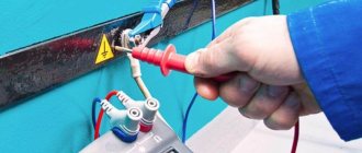
The protective diode, as well as the rectifier diode (including the power diode) or Schottky diode, can be checked using a multimeter (or use an ohmmeter); to do this, we switch the device to the continuity mode as shown in the photo.
Multimeter mode in which semiconductor rectifier diodes are tested
We connect the probes of the measuring device to the terminals of the radio element. By connecting the red wire (“+”) to the anode and the black (“-”) wire to the cathode, the multimeter (or ohmmeter) display will display the threshold voltage value of the diode being tested. After we change the polarity, the device should show infinitely high resistance. In this case, we can state that the element is in good condition.
If, when connecting back, the multimeter registers a leak, it means that the radio element has “burnt out” and needs to be replaced.
Note that this testing technique can be used to test diodes on a car generator.
Zener diode testing is carried out according to a similar principle, however, such a test does not allow one to determine whether the voltage is stabilized at a given level. Therefore, we need to assemble a simple circuit.
Read also: How to choose a compressor for a sandblasting machine
Testing using a regulated power supply
Designations:
- PSU – adjustable power supply (displaying load current and voltage);
- R – current-limiting resistance;
- VT – Zener diode or avalanche diode under test.
The verification principle is as follows:
- we assemble the circuit;
- set the multimeter mode, which allows you to measure DC voltage up to 200 V;
Selecting the required mode for testing
- turn on the power supply and begin to gradually increase the voltage until the ammeter on the power supply shows that current is flowing through the circuit;
- connect the multimeter as shown in the figure and measure the stabilization voltage.
Video
Coffee capsules Nescafe Dolce Gusto Cappuccino, 8 servings (16 capsules)
435 ₽ More details
Coffee capsule Nescafe Dolce Gusto Cafe O Le Coffee with milk, 3 packs of 16 capsules each
1305 ₽ More details
Gaming steering wheels