Thyristors are used in many electronic devices, ranging from household appliances to high-power power plants. Due to the characteristics of these semiconductor elements, it is difficult to check their serviceability using only one multimeter. As a last resort, you can determine the breakdown of the transition. For full testing, you will need to assemble a simple circuit; its description will be given in the article.
Let's start with the preparatory stage, namely with what we need to do before the test.
Thyristor check
Despite high reliability and long service life, such radio electronics can fail due to various overloads, overheating, voltage surges and manufacturing defects. Before purchasing a new device, you should make sure that the part you are replacing is actually damaged. That is why it is important to understand how you can check the performance of a thyristor without the help of specialists.
The entire verification process is based on an understanding of what voltage such a radio element is controlled by (we are talking about negative or positive voltage). It doesn’t matter if the markings are erased, since you can always change the probes and immediately check the performance again. There are several testing methods: using a homemade device, which is assembled from a AA battery and a small light bulb, as well as using special devices (multimeter, oscilloscope, ohmmeter or tester). Let's consider these methods in more detail.
How can you check a thyristor for serviceability?
To test the thyristor for functionality without desoldering it, you can use special devices:
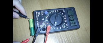
- Multimeter. At the ends of the probes of the device there is voltage that can be applied to the electrode. To do this, the anode and electrode are closed. As a result, the resistance drops sharply: this can be seen on the multimeter. This indicates that the thyristor has opened. If you release the multimeter, it will again show infinite resistance.
- Tester. To check, you will need not only a tester, but also a power source from 6 to 10 Volts, as well as wires. It is necessary to turn on the tester between the cathode and the anode, and then connect the battery between the control electrode and the cathode. If power is not supplied, the thyristor does not work correctly. Also, if the power is constant at any voltage, then the element also does not work correctly.
You may be interested in this Metal detector for wiring
This is how the described thyristor element circuit looks like in practice
Thus, it was considered how to test the thyristor for performance and the main methods for checking it. You can check the correct operation and ring the state of the thyristor using several methods: multimeter and tester. Both do an excellent job.
Special electrical measuring instruments
If you have a special electrical measuring device nearby, checking the thyristor with a multimeter will only take a couple of minutes. The algorithm of this method is simple:
- switching the multimeter to the position of measuring resistance with a range of up to 2000 Ohms (ohmmeter);
- connect the black probe to the cathode, and the red probe to the anode;
- attach the red probe to one end of the switch;
- evaluate the performance by turning it on and off (if the current passes unhindered, then the thyristor is working);
- if current conduction is not observed, it is necessary to swap the probes (if this does not help, the thyristor can be considered faulty).
In this case, the power source is the multimeter battery, and the indicator is digital or dial indicators.
Testing a thyristor with a tester will require wiring, a battery, and the electrical measuring instrument itself. You should proceed according to the following scheme:
- a tester is turned on between the anode and cathode (the device should show “infinity”);
- a power source (battery) is connected between the control electrode (CE) and the cathode, reducing the resistance.
The device can be considered to be functioning incorrectly if there is no power or if the supply to the electrodes is constant at any voltage.
You can also check the operation of the element with an ohmmeter. The algorithm for this method is also not complicated: you need to connect the positive probe to the anode, and the negative probe to the cathode (if done correctly, the ohmmeter will show high resistance). Next, you should short-circuit the control electrode and the anode terminal, which should lead to a sharp drop in resistance.
Before testing a powerful thyristor, you must have a multimeter with special current clamps on hand, since performance testing will be carried out with the equipment turned on. It is extremely important to follow safety precautions when performing the process and read the operating instructions supplied with the equipment.
Circumstances may arise such that it is necessary to test the functionality of the thyristor, excluding desoldering from the circuit. This means that the first step is to disconnect the control electrode and connect the electrical measuring device to the cathode and anode in constant voltage mode (the board must be de-energized). Next, you will need to connect a second testing device in ohmmeter mode to the UE and the anode. The readings of the first tester will not go beyond a few tens of millivolts. If the readings differ, the probes should be swapped.
Characteristics and operating principle
According to the diagram that will be presented below, we can consider the principle of operation of the element. A light bulb is connected to the anode of this radio element, to which the positive terminal of the power source is connected using switch K2. The cathode of the radio element is connected, accordingly, to the power supply minus. When the circuit turns on, voltage is supplied to the element, but the light bulb still does not light. By pressing switch K2, electric current will pass through the resistor and go to the control electrode and the light bulb will begin to glow.
1 kOhm thyristor connection diagram
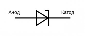
Important! This is the essence of a thyristor. On the diagram it is often denoted by the Latin letter G, which means the English word Gate (translated into Russian as a gate or gate).
You may be interested in Measuring the capacitance of capacitors
The resistor works in such a way that it limits the flow of current from the control pin. The minimum operating current of such an element is 1 mA, and the permissible current for operation is 15 mA. It is because of this that a resistor with a resistance of 1 kOhm is selected. If you press the switch again, nothing will change. You can close it by turning off the power. Thus, a thyristor is a kind of latching electronic key.
Thyristor with connected wires
As far as technical characteristics are concerned, it all depends on the model of a particular element. In general, this element is characterized by:
- Reverse voltage;
- Closed voltage;
- Pulse;
- Repeating impulse;
- Medium voltage;
- Reverse current;
- On and off time;
- Constant pressure;
- Current in open voltage.
Connecting a light bulb to a thyristor
Light bulb and battery
Before checking the KU 202N thyristor, you will need to prepare everything you need. This method will require a AA battery (1.5 volts), a small light bulb, a power supply, a soldering iron and three wires. It is important to remember that the load should be applied briefly. Instead of a battery, you can use multimeter probes.
The algorithm is as follows:
- The negative voltage is connected to the cathode through the light bulb, and the positive potential from the power supply is supplied to the anode (if the light bulb lights up, it means the radio element is faulty).
- Using probes or a 1.5-volt battery, voltage is applied to the control electrode and the light comes on.
- The battery or probes are removed, but the light continues to light.
- A reverse voltage is briefly applied to close the thyristor (you can simply break the circuit by removing the light bulb or probes).
Breakdown testing
Let's start with a preliminary check, which will consist of measuring the resistance between outputs “K” and “UE”, then “A” and “K”. The algorithm of our actions will be as follows:
- We turn on the device in the “continuity” mode and take measurements from the transition between the “K” and “UE” terminals, in accordance with Figure 3. If the semiconductor is working properly, the transition resistance will be displayed in the range from 40 Ohms to 0.55 kOhms.
Fig 3. We measure the resistance between the UE and K - We swap the probes and repeat the process, the result should be approximately the same as in step 1. Note that the greater the resistance between the “UE” and “K” terminals, the lower the opening current, which means the higher the sensitivity of the device.
- We measure the resistance between terminals “A” and “K” (see Fig. 4). The multimeter indicator should display an infinitely large resistance, regardless of the polarity of the connected measuring device. A different value indicates a breakdown in the transition. To ensure a “clean” test, it is better to remove the suspicious part and repeat the testing.
Fig. 4. Measuring the resistance of the Anode-Cathode junction
As mentioned above, this method of testing with a multimeter does not allow us to fully test the performance of the thyristor; we will need to complicate the process somewhat.
Some useful tips
A few recommendations before ringing the thyristor:
- it is necessary to familiarize yourself with the technical characteristics of the radio element in order to act more confidently and effectively;
- it is better to use modern devices, since they are very easy to operate and can provide more accurate information;
- When collecting diagrams, it is necessary to maintain accuracy and carefully monitor the sequence of actions;
- Compliance with safety precautions will prevent damage to electronics and harm to health.
Functionality check
The second testing option is as follows. A lamp at the same voltage is connected to the DC power supply through a thyristor.
A multimeter is connected to the anode and cathode in DC voltage measurement mode. The measurement range must be greater than the source voltage.
Then, control voltage is supplied to the control electrode using a battery of any rating and a pair of wires. The thyristor should open and the light should light up.
The tester first shows the voltage of the power source, after exposure to a small value, which corresponds to the potential drop across the thyristor in the open state.
After this, you can remove the control action, the lamp will continue to burn, since the current flowing through the device is greater than the holding current.