Metal drawing and its types
Main types of rotary metal drawing:
Step molding
A sheet blank in the shape of a circle is fixed between the mandrel and the support. The mandrel must match the internal configuration of the product. The drive begins to rotate the blank, and controlled forming pressure is carried out by a special passive roller driven by the rotation of the blank. Pressure is applied in both longitudinal and radial planes. The roller presses the metal against the mandrel and moves along a complex curve, either towards the edge of the blank or back.
The clamping is carried out in several passes, in steps. At the end of the treatment, a series of smoothing movements of the roller are carried out with reduced pressure to obtain a high-quality surface.
Projection - One-Pass Molding
Extraction is carried out in one pass. The roller moves parallel to the mandrel, depending on the angle of its installation, the wall of the blank is thinned more or less, its material moves under the influence of the roller in the axial direction.
Projection - One-Pass Molding
The method is characterized by efficiency and dimensional accuracy, as well as a high class of the resulting surface.
Rolling with or without mandrel
In this case, the outer diameter of the workpiece is reduced with a simultaneous thickening of its wall due to the redistribution of the material. Rolling is carried out towards the center, in several passes.
Rolling with or without mandrel
As an option, the part is formed by individual segments of the mandrel using a roller with an offset center. Cutting, additional profiling or flanging are carried out as final operations.
Combined
For parts with complex configurations, stepwise forming, rolling, profiling and cutting are used together in various combinations.
Sheet stamping
Sheet stamping is a method of manufacturing flat and three-dimensional thin-walled products from sheet material, tape or strip using stamps on presses or without the use of presses. Sheet stamping is divided into hot and cold.
Hot stamping. It is mainly used in the production of boiler bottoms, hemispheres, buoys and other hull parts for shipbuilding. They are made from steel sheet with a thickness of 3. 4 mm. Hot sheet metal stamping operations are similar to cold stamping operations. However, when designing a technological process, heating is always taken into account. When drawing up a drawing of a workpiece, it is necessary to take into account the shrinkage of the metal during cutting, punching and bending, as well as the degree of warping when the part cools, since its dimensions are somewhat reduced. This circumstance forces us to increase dimensional tolerances in comparison with cold stamping. Workpieces are heated in flame and electric furnaces, as well as in electric heating devices.
Cold stamping . This is the most progressive method of pressure processing, since it allows you to obtain parts that in most cases do not require further cutting. Cold sheet stamping is used to produce both large and small parts (car frames and bodies, aircraft chassis, ship trim elements, watch mechanism parts, etc.).
Sheet stamping allows for greater savings in metal usage while at the same time providing high productivity. But it gives the greatest effect in mass and large-scale production.
Cold sheet stamping uses carbon and alloy steel, aluminum and its alloys, copper and its alloys, as well as non-metallic materials: cardboard, hard rubber, leather, rubber, fiber, plastic, supplied in the form of sheets, tapes and strips.
Sheet stamping technology. The main technological equipment for the manufacture of products by sheet stamping are vibrating shears (Fig. 77), crank presses (see Fig. 87 and Fig. 88) and hydraulic presses. Sheet stamping operations can be divided into two main types: parting and forming. The main separating operations include: cutting, punching and punching.
Cutting is an operation where sequential separation of part of the workpiece occurs along a straight or curved line. Cutting is used to obtain both finished parts and cutting the sheet into strips of the required width. When cutting a sheet, it is necessary that the output of parts from the sheet is maximum and waste is minimal. The rationality of cutting is determined based on the calculation of the material utilization rate. The coefficient is understood as the ratio of the area of the cut parts to the area of the sheet. The cutting operation is carried out using vibrating, disk, guillotine and other shears.
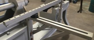
Vibrating shears (Fig. 77) are a machine with short knives. The upper knife 5 receives oscillatory movements from the electric motor 1 through an eccentric mechanism. The sheet metal is installed on the table 7 and moved between the upper 5 and lower 6 knives until it stops 3, which can be moved and secured in the frame bracket, 2.4 - the head, 8 - the bed stand.
Cutting is an operation to obtain a closed-loop blank (Fig. 78). In Fig. 79 shows drawing (I) and diagram (II) of a typical part made from strip by cutting.
Punching - making holes in a part of the desired shape (Fig. 80).
The main forming operations * include bending, drawing, flanging, crimping and forming.
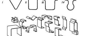
Bending is an operation in which a flat workpiece is given a curved shape (Fig. 81: 1 - punch; 2 - neutral layer; 3 - matrix): R and r - outer and inner bending radii, S - thickness of the material. It can be V-shaped, U-shaped, etc. (Fig. 82).
In Fig. 83 shows a drawing of a part in which the holes are made by punching. After this, the part is bent on the die.
Drawing is an operation that turns a flat workpiece into a hollow spatial part or semi-finished product 2 (Fig. 84). The hood is used to produce not only cylindrical parts, but also complex-shaped box-shaped, conical and hemispherical ones. When drawing, the flat workpiece 5 is pulled by the punch 1 into the hole of the matrix 3. To prevent the formation of folds in the workpiece under compressive stress, clamps 4 are used.
The hood can be without thinning or with thinning. In the first case, it occurs without a noticeable change, in the second, not only the shape of the workpiece changes, but also the thickness of its walls. In the case when it is necessary to obtain a deep drawing, it is carried out in several passes. In Fig. 85 shows a drawing of a typical part made from metal sheet 1, made by stamping with drawing.
Beading is the operation of forming edges along the outer contour of a sheet blank or around pre-punched holes (Fig. 86). It is used mainly for the formation of necks in flat parts 2, necessary both for threading and welding or assembly. Usually it is performed sequentially (I, II, III) in one or several passes in dies consisting of punch 1 and matrix 3. The flanging operation is very often performed at the ends of pipes when connecting flanges to them, with the help of which the pipes will be connected in the future.
Rotary metal drawing process
As a rule, a sheet plate in the shape of a circle is used as a blank. In addition, for some parts other flat shapes are used - an oval or an ellipse, as well as complex curvilinear closed contours. Blanks are also used - sections of pipes, most often round.
Preparatory operations for unique parts and small series are performed on round cutters. In the case of large series, cutting is more efficiently performed on hydraulic cutting machines, due to the fact that laser or plasma cutting is associated with high temperature exposure in the cutting area. This may impair the ductility of the material.
Rotary metal drawing process
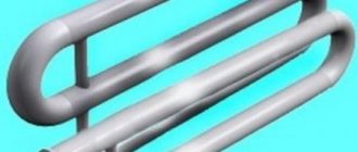
Rotary drawing technology is used in the production of pipe-shaped products with varying diameters and wall thicknesses. In addition, it is possible to form stiffening ribs on the outside. Rotary metal drawing is also used in complex technological processes in conjunction with stamping, welding, riveting and metalworking operations.
Methods for rotary drawing of metal
The variety of techniques for rotary drawing of metal comes down to one of two types:
- Straight. The metal moves along the forming roller.
- Back. The metal moves against the movement of the forming roller.
Direct method
The outer contour of the punch corresponds to the inner contour of the future product (taking into account the necessary allowances). Because of this, the mandrel is made longer than the product. The design of the punch becomes more complicated, the weight, cost and labor intensity of debugging the technological process increases.
Direct method of rotary drawing of metal
This method is applicable for molding parts in the form of a cone and cylinder with a large ratio of length to diameter and diameter to wall thickness.
Back
In this case, the mandrel must match in size and shape with the inner surface of the workpiece, which makes it possible to make the mandrel much shorter than the future product.
Thick-walled rotary hood
The method is used in the production of products with a small length-to-diameter ratio and relatively thick walls.
Rotary metal drawing operations are also divided into forming:
- With thinning, the outer size is maintained, the wall thickness is reduced.
- Without thinning - the wall thickness is maintained during processing, but the outer diameter changes.
- With rolling, the outer diameter is maintained, the wall thickness increases.
Main types of rotary metal drawing
The workpiece is secured between the mandrel fixed to the drive and the caliper clamp.
Deep drawing of sheet metal
Deep drawing Deep
drawing is a process in which a hollow part of any shape is obtained from a flat blank. Shaping is the result of plastic deformation, accompanied by displacement of a significant part of the processed metal along the height of the product. With a large degree of deformation and a small thickness of the starting material, an unfavorable stress-strain state occurs, which leads to the formation of corrugations, cracks, and ruptures of the metal. Parts obtained by deep drawing, depending on their shape, are divided into three groups: 1) axisymmetric (cylindrical, conical, stepped, curved, etc.); 2) box-shaped; 3) complex asymmetrical. Such parts are produced in two ways: 1) by deep drawing without thinning the wall. 2) deep drawing with wall thinning. In deep drawing without wall thinning, the process is carried out by continuously moving the punch with the workpiece into the die, as a result of which the outer diameter of the workpiece continuously decreases. The degree of deformation along the height of the generatrix of the cylinder continuously increases and is maximum at its end. The unevenness of the deformation also determines the unevenness of the work hardening along the height of the part. The thicknesses of the initial workpiece and the resulting product are different, and the thickness of the bottom of the product is close to the thickness of the workpiece, and at the transition of the bottom part to the side wall a thinning (10-25%) is formed, and at the end of the product there is a thickening (15-25%). Wall thickness at the end for part I without a flange and for part with a flange where and si is the wall thickness at the end of the part without a flange and with a flange; r - coefficient; I—workpiece thickness; D3—diameter of the workpiece; D is the outer diameter of the part; flange diameter. The amount of thinning of the transition from the bottom to the wall is related to the radius of rounding of the corners of the matrix, the degree of deformation, the gap between the matrix and the punch, the clamping force of the workpiece and the conditions of contact friction. Deep drawing with wall thinning is characterized, along with a change in the thickness of the starting material, by a decrease in the outer and inner diameters of the workpiece. When developing a drawing technology with thinning, the calculated volume of the sheet blank should be 15-20% greater than the volume of the product (trimming allowance). The number of operations is determined depending on the degree of deformation, where F and f2 are the cross section before and after deformation, mm; and I—wall thickness before and after deformation, mm; t is the elongation coefficient. Height of the elongated part where d is the internal diameter of the part. When deep drawing cylindrical parts, the diameter of the workpiece can be determined in several ways, using the equality of the areas of the workpiece and the finished part (when drawing parts without wall thinning) or the equality of the volumes of the workpiece and the finished part (when deep drawing parts with wall thinning). When applying the calculation method based on the equality of the areas of the workpiece and the finished part, the allowance for trimming is also taken into account. The area of a part is calculated by dividing it into simple geometric elements depending on its shape. The sum of the calculated areas of the individual elements of the product determines the area of the workpiece. The method of calculating D3 based on the equality of the volumes of the initial workpiece V3 and the finished part Ud, taking into account the required volume for trimming, is used when drawing with wall thinning. The volume of the elongated part is determined by the difference between the volumes of the outer and inner cylinders: where s is the thickness of the workpiece, mm. Determination of the degree of deformation and elongation coefficient. Depending on the relationship between the height and diameter of the part, as well as the thickness of the sheet blank, drawing can be carried out in one or several transitions. Determining the number of transitions is one of the most important tasks for a technologist, who must take into account the following basic indicators: drawing coefficient where D is the diameter of the part, mm. The permissible value of the drawing coefficient depends on the shape and dimensions of the part, its mechanical properties, the state of the workpiece surface, the thickness of the starting material, the geometric shape of the punch and matrix, the drawing method (with or without clamping), lubricant, etc. In Table. 8.4 shows the optimal permissible drawing coefficients for cylindrical parts without a flange (when drawing with a clamp) depending on the thickness of the workpiece for steels 08, YuG and 18G. In this case, small values of m must be used for small edge radii (r - 4-H8S), and large values for large edge radii (r = 8 h - 15s). Table 8.4 Deep drawing coefficient t for parts without a flange When drawing low-carbon steels, cold-rolled aluminum, the drawing coefficient should be increased by 1.5-2.0%, and when drawing steels 05, 08, 10, aluminum and other materials, it should be reduced by 1.5-2% compared to the values given in table. 8.4. If intermediate annealing is used, the drawing ratio for each subsequent operation is increased by 2.5–5%. In practice, in some cases, traction can be carried out without pressure. Clamping is recommended when the condition is met. When carrying out technological calculations, along with determining the number of individual transitions, it is necessary to calculate the height of the cylindrical part according to the transitions. The formulas used for this purpose are given in table. 8.5. Determination of pulling and pressing force. Engineering calculations when determining the clamping force are based on the fact that the permissible stresses in dangerous sections must be less than the fracture stress of the deformable material.
Machines for rotary drawing of metal
To implement the technology, the following types of machines are used:
- Pressing and rolling machines for rotary drawing of metal.
- Rotary forging machines.
- Round cutters.
On manual lathes, molding is performed by the muscular strength of the worker. Used to produce unique products or especially small series. For medium and large series, pressing and rolling (rolling) machines with numerical control are used. Hydraulics or electric drives, controlled by a controller according to a program loaded into the central CNC unit, allow precise control of the force and direction of the clamp, as well as the direction of movement of the roller, including the most complex curved trajectories. Such machines ensure absolute identity of products in a series, which is especially important for jet engine parts and other high-tech products
Scheme of forging on rotary machines
Rotary forging machines allow you to form conical-shaped products from pipes by crimping the pipe with a special tool - a forging die. The peculiarity and main advantage lies in the unique ability to produce products that have:
- the length is many times greater than the diameter.
- along the length, the diameter and opening angle of the cone can be repeatedly changed.
- knurling of stiffeners is required.
Round cutters
Circular cutters are designed for cutting rolled sheets into flat pieces in the shape of a circle or ellipse. Also used are both manual and electro-hydraulic.
Scope of application of rotary metal drawing
The method is used to produce:
- jet engine parts in weapons systems;
- tank bottoms and covers;
- various screens in radio engineering, including radar screens;
- thin-walled vessels of complex shape: cans, teapots, cylinders, kettles;
- parts of construction mixer bodies;
- parts of fans and exhaust hoods.
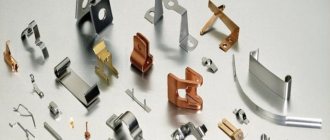
Products made by rotary drawing
The method is also used in the production of contemporary art objects and in the studio for customizing unique motorcycles and cars.
Scope of product application
According to foreign data, the widest area of application of crush-rolling processing is the production of parts for jet engines and guided missiles, as well as the bottoms of radar screen tanks, searchlight housings, and lamp screens.
For example, this method is used to produce:
- The conical part of the exhaust pipes is made of 3 mm thick sheet steel; the finished part has a cone angle of 34°, the diameter of the base of the part is 500 mm, height is 640 mm, wall thickness is 1 mm;
- Nozzles (nozzles) made from stainless steel blanks, conical in shape, 127 mm long, processed on lathe-type machines. After rotary drawing, the nozzle has the following dimensions: height 305 mm, wall thickness 1.14 mm, part cone angle 12°;
- Bearing housing (ring). The workpiece is a machined forging of alloy chromium steel. The largest diameter of the finished part is 508 mm, the cone angle is 84°, the wall thickness along the cone is from 3.2 to 2.3 mm;
- Compressor rear casing. Welded blank made of stainless steel sheet. After rotary drawing, a hollow cylindrical part with an internal diameter of 710 mm and a length of 197 mm is obtained. The part is then machined internally and externally to achieve a wall thickness of 6.4mm. The operations of edging, turning and pressing-rolling produce five internal ribs and a wall thickness of 1.5 mm while increasing the length of the part to 380 mm. At the end of processing, the operation of applying corrugations is performed using specially shaped rollers.
Rotary drawing can easily produce massive tubular parts with variable thickness of machined wall ends and external annular ribs. In combination with rotary drawing, additional operations can be used to obtain complex shapes of parts: rolling, stamping, welding. Rotary drawing can also be used as an auxiliary tool for giving the final shape to the workpieces obtained by drawing. Often, pressing machines process individual sections (parts) of parts assembled by welding or riveting. This makes it possible to produce tubular parts with different combinations of sections.
It is effective to rotary draw long copper conical parts used in some industries. It is difficult to produce such parts on presses, if, in addition, there are strict requirements for the quality of their surface.
A rotary hood is also useful for making household utensils and similar thin-walled products of complex shape: ladles, cups, cans, teapots, coffee pots, cylinders, kettles, barrels, round parts of fans and exhaust hoods, shaped copper parts of brewing installations, concrete mixer drums, large vessels and utensils products for the chemical and food industries.