tubular screw conveyors made of n
rigid and flexible screw conveyors
Jun 27, 2017· Rigid augers. Tubular screw conveyors in a stationary or mobile configuration, designed for loading silos or for transporting grain and feed from silos to different unloading points.
BIOLOGICAL LOAD8
Plant and production LLC NPK "Techvodpolymer" PRODUCTS. TANKS AND CONTAINERS. Rectangular tanks and containers (RVS, RGS)
Silo filter, auger, level sensors from WAM
SCREW CONVEYOR FOR SILAGE te, tp (wam, ITALY) Screw conveyors (conveyors) of the te and tp series are tubular screws that are specially designed for heavy (TR) and especially heavy (TE) working conditions.
Heavy Duty Screw Conveyor TP-TE
Heavy-duty auger conveyors tp and te are used in mineral processing, glass production, foundries, cement plants, gypsum and lime production, and mining.
Screw conveyor: sale, price in Minsk. conveyors.
Belt conveyors; Components made of stainless steel; Bunkers and silos; Screw conveyors; Conveyors with modular belt; Devices and.
suppliers belt conveyors purchase estimates | Europages
Specialist in the field of drive belts and conveyor belts since 1936, tanals, an Alsatian manufacturer, promotes and develops technical solutions aimed at improving performance.
Screw conveyors
In the food industry, stainless steel screw conveyors are used to eliminate the possibility of oxidation of food products.
Screw (screw) conveyor, conveyor buy in.
7. Stainless steel screw conveyor. Call our toll-free number 8 800 indicated in the ad (the call is free from any region of the Russian Federation)
CIRCULATORY AUGER CONVEYORS Ag-Projekt
Screw conveyors (skag stripping screws, psr tubular screws). tubular psr) . An innovative solution is to place a gasket inside the pipe made of a material with a reduced coefficient of friction.
Prices for screw (screw) conveyors - buy at.
Buy screw (screw) conveyors in Cherkassy - prices, products and »: +380 (47) office/fax
Canagro screw conveyors (KanAgro), driven in .
Canagro screw conveyors (KanAgro), driven by a hydraulic motor. Tubular augers driven by a hydraulic motor are designed for installation on a vehicle. . Extractor from .
Contacts – Factory and production in Russia
Your name (required) Your e-mail (required) Your phone (required) File (Upload for calculation.)
Online store of agricultural goods
from 8-00 to 21-00 Mon-Fri; from 10-00 to 21-00 Sat-Sun - at other times, write requests via the website, email, WhatsApp, Viber or SMS
Pneumatic transport, screw and belt conveyors.
Pneumatic transport, screw and belt conveyors, bulk material conveyors. Roller support, installation of a roller support - serves as a support, consisting of one or more rollers, for a drain.
flexible screw feeders ssc
Shaftless screw conveyors ssc for . Shaftless screw conveyors ssc are one of the latest developments in the field of transportation of bulk products.
CycloPhens OWO
cyclelowent. The axial fan (toc) is a modular design that includes: an electric motor module, two or one rotor, air flow control, impurity separation system, cyclone.
3D models and drawings of screw feeders (Screw conveyors)
According to GOST 2037-43, screw conveyors are manufactured with a diameter of 100, 120, 150, 200, 250, 300, 400, 500 and 600 mm. The screw conveyor (Fig. 124) consists of a fixed chute 1, inside of which a screw 2 is installed.
used conveyors and belts complete for a crusher in the south
used conveyors and belts complete for a crusher in the south, drawings of a vibrating screen from China, belts for a vibrating screen grafika24. vibrating screen size from China ascrane. vibrating screen belts biabarbados. vibrating sieve with pneumatic vibrator.
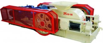
roller-screw crushing plants
roller-screw crushing plants The crushing complex includes a vibrating feeder, a jaw crusher, an impact crusher, a vibrating screen, belt conveyors, etc.
screw feeders
Sluice and screw feeders. Feeders, Chains, Gates for . Screw feeders. Designed for feeding dry products into weighing dispensers, mixers and other devices.
Czech crushing screening line - Mining machine
Exhibition participants 2014 - St. Petersburg - Lenexpo. March 21, 2014 The goal of the alliance is to promote Czech companies, their Mechanical engineering, Production of crushing and screening equipment for solid waste, Mechanical processing.
Stainless steel screw conveyors
tubular screw conveyors made of stainless steel on . Screw conveyors. Flexible spiral augers, vertical auger, screw conveyor, .
Scale drawings.ru | Conveyors - page 3
One of the ways out for . In the past, conveyors were used by people, for example several thousand years BC. e. in Ancient China and India for continuous supply of water from reservoirs to irrigation systems.
Installation of screw conveyors
In order for the screw conveyor to work productively and without annoying failures, attention should be paid to the correct choice of location for its installation and installation and configuration of the unit. https://www.youtube.com/embed/7hABui18lQw
The device should be placed on a level, reliable base to prevent it from falling or being systematically soiled.
A very important stage in preparing the unit for operation is its installation. The installation requirements outlined in the assembly manual must be strictly followed. Such work should be entrusted to qualified assemblers who already have experience in working with under-face mechanisms. Violation of the assembly order, installation dimensions and other errors can lead to the following consequences:
- shocks and vibration when turned on and during operation;
- drop in rotation speed, torque, performance;
- accelerated wear of main parts, frequent repairs;
- reduction in service life.
It is recommended to carry out the assembly and installation of horizontal and vertical screw conveyors in two stages.
The first one is preparatory. within its framework the following operations are performed:
- checking the packaging according to the shipping lists of the manufacturing plant;
- re-preservation of mothballed units and parts;
- initial assembly of large units from individual parts;
- preparation of the installation site, including electrical installation work.
After completing the preparation, you can move on to the main stage, which includes work such as:
- installation of lifting and rigging devices;
- supply of large-unit assemblies to the installation site;
- installation of the unit base;
- installation of other parts with mandatory control of inclination angles and installation dimensions;
- checking the correct assembly, turning the screw manually;
- connecting power supply, setting operating parameters and fine adjustment.
First, a test run is carried out without load. If everything is working normally, the blades do not touch the pipe, no extraneous sounds or impacts are heard, you can test the device under load.
PROJECT
- Crushing Equipment CS Cone Crusher
- HCS Cone Crusher
- HJ Series Jaw Crusher
- HPC Cone Crusher
- Mobile Cone Crushers
- Mobile Impact Crushers
- Mobile Jaw Crusher
- PE Jaw Crusher
- Impact Crusher PF
- PY Cone Crusher
- Crusher VSI
- VSI5X Crusher
- Ball Mill
- Belt Conveyor
- High frequency rumble
- Crawler Mobile Crushing Plant
Design and applications
Today, screw conveyors have become very widespread. This is due to the simplicity of the device, as well as its reliability. The operating principle is as follows:
- The main part is represented by a screw, which moves the bulk substance along the chute. At the same time, the screw has a certain shape, which ensures favorable conditions for transporting bulk materials.
- The conveyor body is represented by a trough, the lower part of which resembles a cylinder. The absence of edges eliminates the possibility of accumulation of transported bulk material.
- The lower part of the propeller is immersed in the transported load. When rotating around an axis, the substance is transported.
- The auger is installed in special supports, represented by bearings. Their use reduces wear.
- An electric motor with a drive is also installed to rotate the propeller. The engine can be powered from a 220 V or 380 V network. As for the drive, in most cases it is represented by a gearbox, the purpose of which is to reduce the number of revolutions and increase the transmitted force.
- The mobile screw conveyor also has a protective casing and two hatches, one is required for loading material, the second for unloading.
The considered operating principle of the device determines that it can be used for horizontal and vertical movement of bulk cargo. At the same time, the purpose of GOST roller conveyors can be significantly expanded through the use of additional equipment.
Screw Conveyors (Screw Feeders)
In industry, screw conveyors (Fig. 124) are used to transport dusty and granular materials (cement, lime, ground clay, fireclay, etc.) mainly horizontally, and in some cases in the vertical direction (Fig. 125).
Screw conveyors often perform both transport and technological functions (for example, transporting and simultaneously mixing materials). They can also be used as feeders.
The advantages of screw conveyors compared to other types of conveyors are their small overall dimensions and the ability to transport goods in closed chutes with little dust generation and minimal loss of materials. The disadvantages of such conveyors include partial crushing of fragile materials during transportation and slightly higher energy consumption. Therefore, they are usually used for transportation over short distances (up to 30-40 m).
According to GOST 2037-43, screw conveyors are manufactured with a diameter of 100, 120, 150, 200, 250, 300, 400, 500 and 600 mm.
A screw conveyor (Fig. 124) consists of a fixed chute 1, inside which a screw 2 is installed. The shaft is supported by suspended bearings 5. When the blades rotate, the material moves along the axis of the chute in the same way as a nut held from rotation moves along the screw. In this case, the role of the nut is played by the material. The latter is kept from rotating along with the propeller blades by friction against the walls of the chute.
The conveyor trough consists of separate sections of standard lengths of 2000 and 4000 mm. The sections are made of steel sheets 3-6 mm thick, to the ends of which flanges made of angles are welded, increasing the rigidity of the gutter and serving to connect the individual sections to each other. The top of the gutter is covered with lids, which are attached to it with staples.
To eliminate dust formation when transporting materials, such as, for example, cement, a sand seal 4 is installed, which hermetically closes the lid.
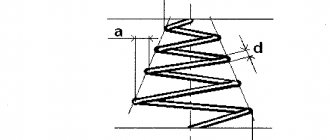
Some factories have installed stepped screw conveyors designed by the Giprocemeint Institute; The plan diagram of such a conveyor is shown in Fig. 126. Such a conveyor consists of sections, each of which has supports only at the ends of the chute. Due to the absence of support bearings inside the chute, the operational reliability of the conveyor has increased. The disadvantage of such conveyors is their high design complexity.
The transport screw (Fig. 127, a) consists of a shaft, usually tubular, to which blades made of sheet steel are welded or mounted on holders, forming a helical surface. The blades are stamped from sheet steel 3-8 mm thick in the form of cut round washers, which are then bent along the helical surface. In standard conveyors, the screw pitch is taken to be 0.8D. The screw is made up of separate sections, each 1500-3000 mm long.
For highly abrasive materials, screws made from individual cast iron sections are sometimes used. In some cases (mainly when moving large pieces and sticky materials), the propeller blades are made in the form of an umbrella spiral spiral conveyors (Fig. 127, b), made by passing steel strips between conical rollers. Sometimes, to work with caking loads, when, in addition to transportation, it is also necessary to mix the materials being moved, propellers with shaped blades or with separate blades are used (Fig. 127, c and d). The screw sections are connected by couplings that have a trunnion in the middle part that fits into the outboard bearing. To give the installation greater rigidity, the lengths of the gutter and screw sections must be different so that their connection points do not coincide. The end bearings of the screw are installed outside the chute on the end posts. To absorb axial forces arising in the screw during conveyor operation, one of these end bearings is made thrust (ball or comb).
Screw conveyor drives are made with gearboxes. The propeller and gearbox shafts are connected by an equalizing coupling, and the gearbox and electric motor shafts are connected by an elastic coupling.
Loading and unloading devices are equipped with valves.
The productivity of a screw conveyor is determined by the formula
In standard conveyors S =0.8D; Substituting this value into formula (239) and performing the calculation, we obtain
The number of revolutions of the screw is taken depending on its diameter and the nature of the material being moved.
The recommended number of screw revolutions per minute according to GOST 2037-43 is given in Table. 41.
The highest number of screw revolutions is for transporting light materials. When moving heavy abrasive materials, as is the case, the number of screw revolutions should be taken in accordance with the table. 42, having previously determined n using the formula
where R = 60, 45 and 30 - respectively for fine non-abrasive, heavy non-abrasive and heavy abrasive material.
Conveyor screw shaft power
where Q is the conveyor productivity in t/h;
Lg is the length of the horizontal conveyor or the length of the horizontal projection of the inclined conveyor in m.
w is the coefficient of resistance to movement, which for heavy abrasive materials (cement, gypsum, fireclay, lime, sand) can be taken equal to 4, and for coal 2.5;
H - material lifting height in m,
Rз = 1.15-1.25 - safety factor.
In our case, the angle of elevation of the helix a = 17 0 40′, the angle of friction between the matella and the screw is p = 35°, r = 0.8D/2 =0.2 m. Based on the force P, a thrust bearing should be selected.
In addition to screw conveyors, screw pipes are used (Fig. 128), which are hollow cylinders into which spirals made of strip steel are inserted and secured, forming a helical surface inside the pipe. The pipe is placed on supports and rotated using a gear ring. The material is loaded inside the pipe and when the pipe rotates, it moves in the axial direction. The performance of a screw pipe is calculated using formula (239).
Advantages and disadvantages
Screw conveyors have a fairly large number of advantages and disadvantages that must be taken into account. An example is that the productivity of a screw conveyor can be very high. The advantages include the following:
- Compact and simple design. Simplicity ensures maintainability and long service life. Compactness determines the possibility of integrating the mechanism into various systems.
- Complete safety of dusty cargo. At high productivity, the basic properties of the transported substance are preserved. Some conveyors, due to their operating principle, can compromise the integrity of fragile materials.
- Low cost is another reason why many decide to purchase and install a screw conveyor.
- The absence of external moving elements significantly increases safety in an industrial structure, and also expands the scope of application of the device.
- Easy to maintain and do-it-yourself maintenance.
However, there are also several significant disadvantages. For example, the performance of a screw is ensured only with a high power consumption. In addition, the length of the device is limited to a small range. When transporting large cargo, there is a possibility of its partial crushing. Long-term operation of the conveyor can cause wear of the main part, which is due to the constant movement of the load. This is why the conveyor has to be serviced periodically. The coefficient for calculation is taken depending on the main parameters of the screw and other structural elements.
https://youtube.com/watch?v=epuGmAuUxQs
3D models and drawings of screw conveyors
Screw conveyor KSh 01
A screw conveyor (or auger conveyor, auger) is a transporting device for bulk, small-piece, dusty, powdery materials. Augers are used in enterprises producing building materials, in the feed mill, flour-grinding and chemical industries to move bulk, small-sized, dusty, powdery materials in horizontal, vertical and inclined directions (usually at a distance of up to 40 m horizontally and up to 30 m vertically ). In machine-building shops it is used for transporting waste chips from machine tools. It is not advisable to use augers to move sticky, highly abrasive, or highly compacted loads. The positive properties of screws include ease of maintenance, simplicity of design, small overall dimensions, tightness, and ease of intermediate unloading. The negative qualities of augers are significant abrasion and crushing of the load, high specific energy consumption, and increased wear of the chute and screw. Classification Screw conveyors are classified • by the inclination of the trough (horizontal, gently inclined, steeply inclined, vertical); • in the direction of the spiral; • by the variability of pitch and diameter of the propeller; • according to the design of the propeller (solid, bladed, tape, shaped). The shape of the screw is selected depending on the type of cargo being transported. Horizontal screw This type of conveyor consists of a drive (gearbox and electric motor), rotating a screw (the working part of the machine), a drive shaft with turns of the transport screw mounted on it, a chute with a semi-cylindrical bottom, a loading and unloading device. A bulk load is fed through the holes in the chute cover and slides along the chute as the screw rotates. The joint rotation of the load with the screw is prevented by the gravity of the load and its friction against the chute. The chute is unloaded through holes in the bottom equipped with shutters. The auger screw is made with one, two or three threads, with a right or left spiral direction. The surface of the auger screw can be bladed, shaped, belt, solid (used when moving bulk powder, dry fine-grained cargo that is not prone to caking). When moving caking loads, auger screws with a bladed, shaped, or belt surface are used. The auger screw shaft consists of separate sections and can be tubular (fastened together using short connecting rollers inserted at the ends, have less weight) or solid. The screw shaft of the auger rests on end bearings (fixed in the end walls of the chute) and intermediate bearings (suspended from above on transverse bars mounted on the chute). One of the end bearings is made thrust and installed on the side where the load begins to move. The intermediate bearings have a small diameter and length, as well as a reliable seal to avoid contamination by cargo particles. Vertical auger This type of auger consists of a short horizontal feeder screw rotating in a cylindrical casing (pipe) and a shaft suspended on a thrust bearing with solid screw turns, also rotating in the pipe, and one or two separate drives for both screws. The auger is unloaded through a pipe at the top of the casing. The load is fed into the lower section of the vertical screw of the auger, and it is made either with a reduced pitch or with a variable diameter decreasing upward. Vertical augers are used to lift loads to a height of up to 15 m, and when moving granular, powdery, and fine-grained materials with limited productivity - no more than 30 m. Vertical augers are used as installations for drilling wells. Vertical augers are energy-intensive, and also have small overall dimensions, making it easy to unload in any direction.
Equipment video
- Registration
To come in
Copyright
All works posted on the website keyprod.ru are subject to copyright
Accordingly, they are subject to the requirements of the law on the protection of exclusive rights to a work. Therefore, works downloaded from this resource are prohibited from being distributed or posted on third-party resources on the Internet.
Types
The most common types of conveyors are:
Screw (auger) conveyor
consists of a groove and an Archimedean screw located in it; used for bulk solids.
- Rope conveyor
- Oscillating Conveyor
used for small objects rolling or sliding on an inclined swaying surface.
Bucket Conveyor
the load-carrying part of the conveyor is buckets, the suspension axis of which passes through the middle point, which allows them to swing; for transporting bulk materials (coal, crushed stone, slag, clinker), buckets are installed with an overlap without gaps, in contrast to mechanisms for gravity loading, like elevators.
Belt Conveyor
consists of an annular belt, tension and drive drums and support rollers; It is usually used for transporting bulk substances; modifications are possible (tubular, z-shaped, rotatable by 90 and 180 degrees) due to the deformation of the belt.
Conveyor with modular belt
consists of a plastic (polyurethane, polypropylene, polyacetal) tape, tension and drive unit with sprockets; used for transporting bulk substances, piece goods, and open products. Conveyors with a modular belt can have a different movement path: rotary, zigzag, spiral.
Plate Conveyor
the load-carrying part of the conveyor is the plates;
- consists of two parallel circuits connected to each other by plates.
- special plastic or stainless steel chains
Pneumatic conveyor
conveyor, the traction of which is provided by air flow
- consists of a tube and closed containers moved along it, tightly adjacent to the walls;
- Bulk material moves in the air flow as a suspension (air chute).
Overhead conveyor
differ in that the moving bodies do not lie, but hang on load-carrying fasteners, and the conveyor mechanisms themselves are also suspended.
Roller conveyor (roller conveyor)
consists of rollers fixed to a frame, individual rollers can be driven, or the entire frame is inclined, as is the case with a gravity roller conveyor; used for large solid objects.
Scraper Conveyor
consists of a chute and scrapers moving bulk material along it, usually attached to a ring chain; unloading can be carried out either at the end of the conveyor or through openings in the chute.
Spiral conveyor (flexible)
consists of a groove and a spiral located in it; used for bulk solids, higher productivity compared to a screw conveyor. consists of a chute and a (wire, ring) rope on which metal discs are attached that move a non-abrasive material (for example, coal) inside the chute.
Trolley conveyor
used for moving assembled and welded units in production lines. When using a floor-mounted trolley conveyor, it is advisable to use trolley platforms for mounting assembly and welding equipment on them.
Walking Conveyor (Stepping Conveyor)
used for moving assembled and welded units in production lines. When using a floor-mounted trolley conveyor, it is advisable to use trolley platforms for mounting assembly and welding equipment on them.
Drawings of mills, conveyors, screens, conveyors and
- Condition: Used
Working drawings for mining machines and equipment.
A database of 20,000 drawings, 130 sets of design documentation for operating equipment that is relevant today.
DRAWINGS OF THE MILL, partially and completely: • Drawings of the tangential mill MMT-1300 • Part of the CD: MSHR-2.1x3.0; 3.6x4.0; 2.4x3.0; 2.7x3.6; MTs-1.25, • MMPS-5000x3400, SM-6001, SM-1456, Sh-16, Sh-16A, Sh-25A, • Sh-50, Sh-50A, MMT-1300, MMT-2000, MV- 2700
DRAWINGS EXCAVATORS, PROCESSING, partially and completely: • Drawings spiral classifier, washing, hydrocyclone, • 2KSN-2.4, 2GMK-14, GC-250, 1KSN-12, 1KSN-15, • Drawings cyclone TsN-15x800, bag filter FR-0.1, separator, • Drawings of excavators EKG-4.6B, EKG-5A, EKG-8I, EKG-10, EKG-12.5 • Drawings of excavators (part of the CD) ESH-10/70, ESH-15 /90, ESh-20/90 • Part of the CD: drilling rig SBSH-250MNA, EKG-15
NOMENCLATURE IN ENLARGEMENT: • Drawings of conveyors, conveyors, belt screws... • Drawings of inertial screens, etc. GIL, GIS, GIT, GSS, GPV • Drawings of rotary crushers SMD, DR, DRO • Drawings of jaw crushers DSCH, ShchDS, ShchD, SMD, SM • Drawings of crushers cone KMD, KSD • Drawings of centrifugal crushers DC, hammer S, SM, SMD • Drawings of swing, plate, belt, roll, • vibrating feeders PC, KT, PP, TK, DRO, PL, GPV, PV • Drawings of semi-mobile units crushing and sorting feed • Drawings of stationary feed units, sorting, crushing • Drawings of the mill MShR, MMT, MV, MTs, MMPS, Sh, SM • Drawings of EKG, ESh excavators, SBSh machine • Drawings of cyclones TsN, bag filters FR, separators and more • Drawings of spiral classifiers KSN, trough gravel washers MMC
WE PRODUCE CD DRAWINGS OF INDUSTRIAL EQUIPMENT: Raymond mills, rotary kilns, vertical mills, ball mills, refrigerators, boilers, gas furnaces, thickeners, flotation machines, jiggers, centrifuges, air separators centrifugal magnetic drum powder rotary combined vortex, cyclones, butars, classifiers non-submersible spiral one two, screw bucket sand washers, vibrating centrifugal dewatering machines, conical drum screens round arc high frequency linear, disc screw feeders piston tray pendulum, granulators, stackers, vacuum filters, shot blasting machines, cement trucks, industrial fans, screw presses, scrubbers , bucket chain elevators, crushers rotary disc roll hammer multi-cylinder hydraulic reversible gear clinker vertical centrifugal impact ring, electric bag jet pulse filters, dust collectors, conveyors belt conveyors self-propelled scraper mobile bucket chain screw spiral suspended caterpillar telescopic, silos, mixers, concrete mixers, concrete stationary mobile modular prefabricated plants, asphalt plants and much more
DRAWINGS OF PARTS OF UNITS UNITS: frame body, support ring, support bowl, crushing cone, drive shaft, gear wheel, tray, receiving hopper, grate, unbalance, eccentric body, Uralmash frame, scrubber, compass, fixed armor, eccentric shaft, butara stone concrete , solid, cheek, Drobmash pulley, flywheel, crushing plate, Kanmash slider, 3d cracker, spacer plate, adjusting, AutoCAD vibrator unit, bearing housing, assembly drawing pusher, tape, blade, plate, download roller block, sprocket model, gateway, roller , drive drum, Metso tension station, detail beam connection, Sandvik spring, general view, 2d counterweight, auger scraper chain, rotor, Terex beater, lining, reflective plate, hammer, and much more
Essential elements
The mechanism under consideration for transporting bulk materials consists of a fairly large number of different elements. The screw conveyor scheme is characterized by the following features:
- As previously noted, screw conveyors move bulk materials. That is why an important design element can be called a screw or auger. It receives force from the drive and transmits force to the material itself. There are quite a large number of different versions of augers: shaped, solid, belt, bladed and others. The performance characteristics of the device largely depend on the shape.
- Solid screws, which are assembled by connecting sections, have become quite widespread. Sheets with a thickness of 2-5 mm are used as the main material. The basis is a hollow shaft.
- The robust screw shaft can withstand a very high degree of impact. That is why it is made up to 50 meters long. However, the required operating conditions can only be ensured by fastening at several points.
- The gutter is represented by a body, which is often made using a metal sheet 2-8 mm thick. As previously noted, the lower part resembles the shape of a half-cylinder. The main parameter can be called the capacity of the structure.
- On the end sides there are special holes intended for installing bearings.
- The gutter is closed with a lid, thereby ensuring the required degree of tightness.
- The main part of the structure can be assembled from several separate sections. The width of the cylindrical part can vary from 5 to 10 meters. The rigidity of the structure can be significantly increased by placing a large number of stiffeners.
- Bearings can also be located in the middle part, which increases the degree of screw fixation. Tail bearings are designed to support radial loads only.
- The drive of a screw conveyor is represented by a combination of a fairly large number of different elements that are designed to change the parameters of rotation and its transmission. The main element is an electric motor, which is connected to a gearbox or a system of pulleys and gears. In most cases, the drive is responsible for reducing the number of revolutions and increasing the transmitted force.
The dimensions of the screw conveyor window are selected depending on what substance will be transported.
Screw conveyor
Screw conveyor is equipment for transporting and dosing bulk materials (granular, dusty, powdery, less often small-piece media). The conveyor can perform the functions of a mixer, dispenser and feeder.
Other names for conveyor: auger, screw conveyor, screw conveyor.
Screw conveyors are easy to maintain, have high tightness, are convenient for intermediate unloading, and eliminate dust generation when transporting bulk media.
Application of screw conveyor
- production of building materials
- feed and flour milling industry
- chemical production
- moving materials in any direction (distance: max. 40 m horizontally - and 30 m vertically)
- transportation of drain chips in machine-building workshops
Not suitable for use on: sticky, highly abrasive, highly compacted working media.
Types of screw conveyors
- Depending on the inclination of the gutter, horizontal, gently inclined, steeply inclined and vertical are distinguished;
- The direction of the spiral may also be different;
- The variability of the pitch and diameter of the screw depends on the design;
- The design of the propeller can be different: solid, bladed, tape or shaped). The shape of the screw is selected according to the type of product being transported.
The working mechanism of a screw conveyor
The horizontal conveyor consists of:
- drive (gearbox with electric motor),
- rotating screw (is the working body),
- drive shaft,
- gutters with a semi-cylindrical bottom,
- loading and unloading openings.
The product is poured into the loading device on the chute; when the screw rotates, the medium passes along the chute to the discharge hole in the bottom. The auger screw can be single, double or triple, with a right or left spiral direction.
The tubular shaft of the conveyor screw is constructed of sections that are connected using rollers; the shaft can also be solid. The propeller shaft can be located in end bearings (in the end walls of the chute) or in intermediate bearings (on top of the transverse bars). Intermediate bearings have small diameters and lengths, as well as a reliable seal to protect against contamination.
The vertical auger consists of:
- horizontal feeder screw in the pipe;
- thrust shaft bearing with solid screw turns,
- one or two drives for screws.
The pipe at the top of the pipe serves for unloading (in any direction). The medium is fed into the lower section of the vertical screw. Maximum load lifting is to a height of 30 m.
Main types of screw conveyors
Screw conveyors BKV (auger in a trough)
Application: flour milling and feed milling industry.
Screw diameter: 160, 200, 250, 320, 400 and 500 mm.
Step: constant / variable.
Conveyor inclination angle: up to 20 0 .
Screw conveyor in the BKV trough
Stationary screw conveyors KV in a trough/pipe
Application: general industrial (working media: cement, sand, gypsum, concrete, coal, dust, etc., bulk density 0.2 - 3.5 t/m3).
Screw diameter: 160, 200, 250, 400 and 500 mm.
Conveyor inclination angle: up to 20 0 .
Methodology for calculating key indicators
Tsam alloys - composition, properties and scope of application
To produce screw conveyors, it is necessary to perform a large amount of design and technological preparation. It includes the production of product drawings, the construction of its kinematic diagram, and engineering calculations.
To calculate a screw conveyor, it is necessary to take into account the main parameters. These include:
- Spiral pitch t. depends on the specific gravity ρ of the transported substance; with increasing density, the step must be reduced.
- Shaft rotation speed n. For light loads, the speed reaches 120 rpm; for dense and viscous loads, the speed must be reduced to 30 rpm.
- Screw diameter d. also decreases with increasing specific gravity and viscosity.
- The gutter filling rate ψ, depending on the density of the material, ranges from 15 to 40%.
- C - correction for the elevation angle, for horizontal devices C = 1, for vertical screw conveyors the value is taken from the tables;
The performance of the screw mechanism is calculated using the formula:
Engine power sufficient for reliable operation of the conveyor with a given performance is determined by:
- mass of the shaft with blades;
- weight of the load in the pipe;
- linear speed of movement;
- a number of correction factors for friction.
Finally, the power is determined taking into account the efficiency of the gearbox and adding the standard power reserve required to start a conveyor filled with cargo.
Complex option
This method of manufacturing a screw will allow you to assemble a high-quality and accurate device that will serve for a long time. First, calculations and drawings are made, then measurements are made. It is also worth preparing tools and suitable material in advance, and only then start assembling a homemade drill.
Step-by-step instructions for installing a screw mixer are as follows:
- Take the prepared pipe, and it should be smooth, without any bends or deformations. Drill a perpendicular hole with a diameter of 8 mm at one end. This is where the top part will connect to the handle.
- Install the tip from below - this part will set the direction of movement of the earth. You can make it from an old car spring. You can cut the required square using a grinder.
- Make a longitudinal cut in the pipe, which should have a thickness equal to the tip. Next you should insert it with its sharp tip inside the pipe. The result should be a device that resembles a spear.
- Connect the parts using a welding machine, not forgetting about safety measures.
- Cut a cutter from the spring equal to ½ the diameter of the drill being made, and cut the teeth on it. It is these elements that will bite into the soil, loosen it, and only after that the soil will fall onto the spiral of a homemade auger.
- Position the cutters so that they are at an acute angle to the main surface. After this, the parts should be welded to the steel pipe.
- Cut a circle from a metal sheet, the same in diameter as the auger spiral. Make a hole in its center into which the pipe will be inserted. Attach the manufactured disk to the cutter welded to the tube. Mark their contact using a pencil or a special marker.
- Using the marks obtained, cut the circle from the edge to the center; it is best to do this with a grinder. Place the cut disk in a vice and twist the elements into a spiral with a hammer. Place the self-made auger onto the pipe and weld it. Finally, brush the surface with a wire brush and paint.
Transport pipes
A type of screw conveyor can be called transport pipes. The main purpose is to move bulk materials that cannot be crushed. It is advisable to use transport pipes if several operations are combined, for example, drying and transportation. The key features of this design option include the following:
- Simplicity and reliability of design.
- At the time of transportation, a high degree of tightness is ensured.
However, there are several significant disadvantages, which are as follows:
- Transporting the material requires quite a lot of energy.
- The design is characterized by large dimensions and weight.
Structurally, the device resembles a pipe, which can be positioned horizontally or at an angle. A two- or three-way spiral can be located inside. There are also versions that do not have a screw element inside.