Hello dear readers of the site. In this article I will tell you how to collect simple power regulator for soldering iron, which allows you to smoothly change the voltage on the heating element, thereby maintaining the optimal temperature of the soldering iron tip.
If the tip is not warmed up enough, the solder melts slowly, and the soldering iron has to be kept pressed to the leads of the parts longer, which can lead to their failure.
Soldering with an overheated tip also turns out to be fragile. The solder does not stick to such a tip, but simply rolls off it.
Hence the conclusion: so that soldering is not painful, and the working part of the soldering iron is always well heated, it needs to be maintained at an optimal temperature.
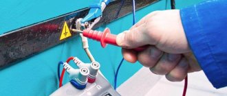
Attention! This design has transformerless AC power supply. When assembling it, pay special attention to compliance with safety precautions when working with electrical installations.
Schematic diagram of the power regulator.
I assembled this circuit so long ago that I don’t even remember when. It was published in the magazine “Radio” No. 2-3 for 1992 by I. Nechaev, and during the entire period of operation of the regulator there was not a single failure.
As you can see, the circuit is very simple, and consists of only two parts: a power circuit and a control circuit.
The power part includes thyristor VS1, from the anode of which an adjustable voltage is removed, through which the soldering iron is connected to a 220V network.
A control circuit assembled on transistors VT1 and VT2 controls the operation of the thyristor. It is powered through a parametric stabilizer formed by resistor R5 and zener diode VD1. Zener diode VD1 serves to stabilize and limit a possible increase in the voltage supplying the control circuit. Resistor R5 dampens excess voltage, and variable resistor R2 regulates the output voltage of the power regulator.
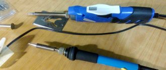
This is the small kit we will need to assemble a power regulator for a soldering iron.
DIY soldering iron power regulator: proven working circuits (6 pcs)
Not everyone likes to buy unknown things. And some people find it more pleasant to make a soldering iron power regulator with their own hands, because this is also experience. Most circuits are assembled using triacs and thyristors; now they are easier to find than transistors. They are also easier to work with, since they are either open or closed, which allows you to make circuits simpler.
Choose any case
Simple thyristor circuits
When choosing a power regulator circuit for a soldering iron, two things are important: power and parts availability. The soldering iron power regulator presented below is assembled using widely used parts that are not a problem to find. The maximum current is 10 A, which is more than enough to perform any kind of work and for soldering irons with a power of up to 100 W. The thyristor in this circuit is used KU202n. Pay attention to the bridge connection. There are many circuits with connection errors. This option is working. Tested more than once.
Temperature controller circuit for a soldering iron using a thyristor
When assembling the circuit, be sure to place the thyristor on the radiator; the larger it is, the better. The circuit is simple, but when it is turned on, it creates interference. You can’t listen to the radio nearby, and to remove interference, we connect a 200 pF capacitor in parallel with the load, and a choke in series. The choke parameters are selected depending on the regulated load, but since soldering irons are usually no more than 80-100 W, the choke can be made at 100 W. To do this, you will need a ferrite ring with an outer diameter of 20 mm, on which about 100 turns are wound with a wire with a cross-section of 0.4 mm².
Another drawback of the diagram translated above is that the soldering iron “itches” noticeably. Sometimes you can put up with this, sometimes you can’t. To eliminate this phenomenon, you can select the parameters of capacitor C1 so that when the variable resistor is set to maximum, the connected lamp barely glows.
On other elements but also without interference
The above regulator can be used for any load. Let's give another analogue, but using a different element base. You can regulate not only the power/temperature of the soldering iron, but also any other load with a small inductive component.
A modified circuit for regulating the power of a soldering iron and any other load with the ripple effect eliminated
There is pulsation here, but its frequency is high and it will not be perceived by our vision. So it can be used not only as a dimmer for a soldering iron, but also to regulate the light from a regular incandescent lamp. Is a diode bridge needed to regulate the heating power of a soldering iron? It won't hurt, but it's not necessary.
On a thyristor with high sensitivity
This circuit allows you to smoothly change the temperature of the soldering iron from 50% to 100%. There are two indicators - power and power. The power presence LED always lights up when turned on, but at 75% power the glow is brighter. The power indicator changes the intensity of the glow depending on the operating mode.
Power regulator for soldering iron without interference
In order for the regulator to fit into the case of a mobile phone charger, resistances are used of SMD type (1206). All resistors are installed on the board, except for R 10. Some can be composite (we assemble the required value from series-connected resistors).
For normal operation of the circuit, a sensitive thyristor (with a low control current) and a low state holding current (about 1 mA) is required. For example, KT503 (designed for voltage 400 V, control current 1 mA). The rest of the element base is indicated in the diagram.
If assembled, but the voltage is not adjustable
If the assembled regulator does not regulate anything - the temperature of the soldering iron does not change - the problem is in the thyristor. The scheme seems to be working, but nothing happens. The reason is a thyristor with low sensitivity. The currents flowing in the circuit are not sufficient to open. In this case, it is worth installing an analogue with higher sensitivity (lower control currents).
One of the housing options in which you can hide a homemade power regulator for a soldering iron
The regulator may still work, but the soldering iron begins to “itch.” This problem is solved by installing a choke at the output (in front of the soldering iron). The capacity must be selected - it depends on the soldering iron. The second solution is an analog control circuit, and this is a different circuit.
Well, if you have problems with operation, look for either faulty parts or incorrectly selected components. This is usually the problem.
Construction and details.
The circuit uses two silicon transistors: KT315 and KT361. Since their cases are the same, they differ in the location of the letter marking. In the figure, these places are indicated by arrows.
For the KT315 transistor, the letter is always located in the upper left corner
case, and for KT361 the letter is always printed in
the middle of the case
. All other designations are: year of manufacture, month, batch.
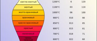
The following figure shows a diode and a zener diode. Here you need to pay attention to the pinout of their conclusions. As a rule, the pinout is applied on the element body in the form of a strip, dot or several dots on the side of the designated pin
.
There are also diodes in which the diode symbol used on circuit diagrams is marked on the body. How exactly the designation is applied to the terminals means that this arrangement of the anode and cathode corresponds to reality.
For imported diodes and zener diodes, a strip is applied on the cathode output side, and for powerful ones, the pinout is applied in the form of a diode symbol.
For Soviet and Russian diodes, the pinout is slightly different from the imported one. Here we use a strip, dots, and the symbol of a diode. In addition, both the anode terminal and the cathode terminal are also designated. So, in any case, it is advisable to use a reference book or measuring device to more accurately determine the conclusions.
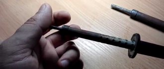
In the power regulator circuit, a thyristor is used as an adjustable element. The thyristor itself resembles a diode, only it has one more terminal - a control electrode.
In the closed state, the thyristor does not pass current, and if an unlocking voltage is applied to its control electrode, the thyristor will open and current will flow through the anode and cathode. The greater the unlocking voltage current, the greater the current the thyristor will pass through itself.
If problems arise with purchasing resistor R5, it can be made from two resistors connected in series. All other details are simple, so we won’t dwell on them.
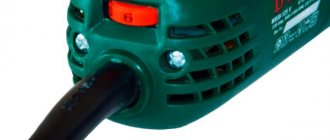
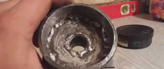
As you may have guessed, we will take a surface-mounted socket as the body of the power regulator. When you buy, pay attention that the socket itself is made of plastic
, not ceramic.
This is necessary so that if suddenly the thyristor does not fit into the housing, then you can always cut off an extra piece from the plastic.
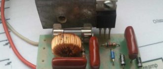
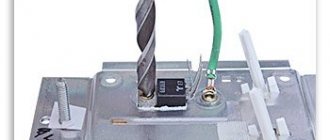
We will assemble the regulator from two parts. It is better to assemble the low-voltage part on foil fiberglass, thick cardboard or any other dielectric material - it will be neater. But we will make the high-voltage part by hanging installation, as shown in the figure below.
Here the holes are indicated by black dots, and all connections between points and parts are paths
, shown with blue lines. The control circuit board and the power section are connected to each other by three red conductors.
Power regulator for soldering iron 20-36 VAC
If the soldering iron operates from a reduced mains voltage of 20-36 V, it is useless to use SCR circuits for it. They practically do not work - the voltage across the trinistor drops by 10-15 V. At the original 220 V, this does not have much effect on the operation of the soldering iron. But at 20-36 V, such a decrease is already critical - the soldering iron operates at half power, which is clearly not enough for normal soldering.
Circuit for a soldering iron operating on reduced mains voltage
What's good about this soldering iron power regulator (and heating element, and other loads without a large inductive component)?
- It gives a voltage drop of only 1.5-2 V, which is not much even for 20 V at the input.
- You can set the power control limits depending on whether you have 20 V AC or 36 V. Variable resistor R4 is responsible for this.
- The same function makes it possible to operate from 45 V.
In general, a universal soldering iron power regulator for low AC voltage networks.
Element base
Most of the element base is indicated in the diagram, but some parts can be replaced.
- Transistor VT1 should be KT815B, you can also install KT815, V and G, KT807 AM and BM; KT817 B, V, G.
- Transistor VT2 - better than KT 814 B V or G, but maybe KT816 B, V, G; GT906 AM.
- The diode bridge VD1 is indicated by KTs401A, you can replace KTs402 A, B, C, D, E. You can assemble a bridge using KD212A, KD213 diodes.
- We install diodes VD3 and VD 4 of any small size - flat or point (D9 series is best).
- Capacitors: C1 and C2 - oxide type K50-3, K 50-6, K 50-24.
- From 3 - K 10-7 or KLS.
- We take resistors from the BC and MLT series.
Is it possible to install items not listed in the list? Only analogues of domestic production are indicated, but there is also an import base. Just be more careful with the characteristics when choosing a replacement.
Installation features
There is a PCB layout for this regulator (in the picture below). We place all the details on this board. Only resistor R4, which sets the adjustment limits, is installed so that it is in the housing. We fasten capacitor C1 in a horizontal position, using wire staples; the rest - no difference.
Printed circuit board for a soldering iron regulator circuit for 20-36 V AC voltage
The parameters of resistors R2 and R3 are selected depending on the desired control limits.
For normal operation, transistor VT2 must be mounted on a radiator. The area is 20-30 cm², the board has space for an L-shaped radiator.
On the front side of the case or on top, in addition to the variable resistor, it is convenient to install a socket for connecting a soldering iron. Actually, these are all installation recommendations.
A simpler option
If you want something simpler, there is a completely workable circuit with a minimum of elements. It generally fits into the case from the charger.
A simple circuit for a low-voltage AC soldering iron regulator
The main modification is to make a hole for the terminal of the variable resistor handle. But no adjustments, everything is “oaky”, but it works.
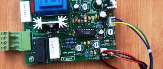
Power regulator control circuit board.
If you do not have experience, then it is better to do the installation on thick cardboard. At the same time, you will understand how the elements are assembled into a circuit, and for such a circuit it is wasteful to spend textolite and ferric chloride. Moreover, almost all radio amateurs started with cardboard or plywood. I myself assembled my first transistor receiver on cardboard.
Everything is very simple here. You make holes in the cardboard and insert radio components into them. Bend the leads on the back of the cardboard and solder them together to assemble the circuit. Take a piece of cardboard to spare. Then cut off the excess.
This is the control circuit board I got.
PS I’ve forgotten how to assemble circuits on cardboard a little, it didn’t turn out very nice, but it’s better than hanging it.
Power part of the power regulator.
We solder the VD2 diode to the anode and cathode of the thyristor. Resistor R6 is soldered to the control electrode and the cathode of the thyristor. Resistor R5 is soldered with one terminal to the anode of the thyristor, and the second to the cathode of the zener diode VD1. The conductor will go from the control electrode of the thyristor to the emitter of transistor VT1.
Now we assemble the power part and the control board into a single circuit. It should look like this.
Everything that we have collected remains to be connected to the socket of the future power regulator.
Be extremely careful here . One mistake, and you can lose a thyristor, a diode, or even create a short circuit .
Just in case, I made a drawing where I indicated where to solder and connect the wires from the regulator circuit and the 220V cord to the socket into which the soldering iron will be inserted.
Before installing all components into the housing, you must check the operation of the power regulator. To do this, insert the soldering iron into the socket of the regulator, switch the measuring device to the AC voltage measurement mode at the highest limit
. In a multimeter it is 750V.
We plug the regulator plug into a 220V power outlet and rotate the variable resistor. If you did everything correctly, then the voltage on the device should change smoothly.
It happens that when the resistor is rotated in the direction, for example, increasing, the voltage decreases. Or vice versa. Here, you just need to swap the extreme terminals of the variable resistor.
From personal experience
. I recommend setting the voltage value at the regulator output to 150 Volts and remembering or marking the position of the variable resistor slider at this value. So that later, when soldering, you can regulate the temperature of the soldering iron tip from this value up or down.
Converters based on controlled diodes
Each of the possible versions of the devices differs in its circuit and control element. There are circuits of power regulators using thyristors, triacs and other options.
Thyristor devices
In terms of their circuit design, most known control units are manufactured using a thyristor circuit controlled by a voltage specially generated for these purposes.
Popular articles Decoupage passport cover
A two-mode regulator circuit based on a low-power thyristor is shown in the photo.
Using such a device, it is possible to control soldering irons whose power does not exceed 40 watts. Despite its small dimensions and the absence of a ventilation module, the converter practically does not heat up under any permissible operating mode.
Such a device can operate in two modes, one of which corresponds to the standby state. In this situation, the handle of the variable resistor R4 is set to the extreme right position according to the diagram, and the thyristor VS2 is completely closed.
Power is supplied to the soldering iron through a chain with a VD4 diode, on which the voltage is reduced to approximately 110 Volts.
In the second operating mode, the voltage regulator (R4) is moved from the extreme right position; Moreover, in its middle position, thyristor VS2 opens slightly and begins to pass alternating current.
The transition to this state is accompanied by the ignition of the VD6 indicator, which is activated when the output supply voltage is about 150 Volts.
By further rotating the R4 regulator knob, it will be possible to smoothly increase the output power, raising its output level to the maximum value (220 Volts).
Triac converters
Another way to organize the control of a soldering iron involves the use of an electronic circuit built on a triac and also designed for a low-power load.
This circuit works on the principle of reducing the effective voltage value on the semiconductor rectifier, to which the payload (soldering iron) is connected.
The state of the control triac depends on the position of the “switch” of the variable resistor R1, which changes the potential at its control input. When the semiconductor device is completely open, the power supplied to the soldering iron is reduced by approximately half.
The simplest control option
The simplest voltage regulator, which is a “truncated” version of the two circuits discussed above, involves mechanical control of power in the soldering iron.
Such a power regulator is in demand in conditions where long breaks in work are expected and it does not make sense to keep the soldering iron on all the time.
In the open position of the switch, a small amplitude voltage (approximately 110 Volts) is supplied to it, ensuring a low heating temperature of the tip.
To bring the device into working condition, just turn on the S1 toggle switch, after which the soldering iron tip quickly heats up to the required temperature, and you can continue soldering.
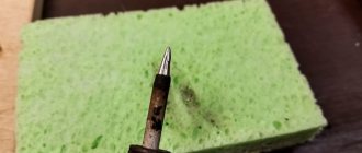
Such a thermostat for a soldering iron allows you to reduce the temperature of the tip to a minimum value in the intervals between solderings. This feature slows down oxidative processes in the tip material and significantly extends its service life.