Mounting options
Power regulator assembly diagrams can be either simple or complex.
You will need:
- Dimmer box;
- Printed circuit board;
- Radio components for circuit assembly;
- Soldering iron;
- Solder;
- Flux;
- Tweezers.
The case can be made of plastic by cutting out blanks and gluing the box, or matched to the size of the board using an old charger, tee, single or double external socket, etc.
It is important that the entire microcircuit fits in it and that the device is comfortable to operate. The selection of the housing depends on both the power and the tasks of the voltage regulator.
If the dimmer is made for a soldering iron, then it can be mounted in a pre-purchased soldering iron stand. When you need to regulate the power of an incandescent lamp or the rotation speed of a fan, it must be placed so that it is convenient to use. It is better to install it in the device case when there is space inside it, or rigidly attach it to it.
Types of modern devices
The development of semiconductor technology has made it possible to control power using radioelements with an efficiency of eighty percent. This made it possible to comfortably use them in a network with a voltage of 220 volts, without requiring large cooling systems. And the advent of integrated circuits made it possible to achieve miniature sizes of the entire regulator as a whole.
Currently, production produces the following types of devices:
- Phase. Used to control the brightness of incandescent or halogen lamps. Another name for them is dimmers.
- Thyristor. The operation is based on the use of a delay in switching on a thyristor switch during a half-cycle of alternating current.
- Triac. Power is regulated by changing the number of voltage half-cycles that act on the load.
- Travel regulator. Allows you to smoothly change the electrical power supplied to the electric motor.
In this case, the adjustment occurs regardless of the shape of the input signal. Based on their location, control devices are divided into portable and stationary. They can be carried out either in an independent housing or integrated into the equipment. The main parameters characterizing electrical energy regulators include:
- smooth adjustment;
- operating and peak power input;
- range of input operating signal;
- Efficiency
Thus, a modern electrical power regulator is an electronic circuit, the use of which allows you to control the amount of energy passed through it.
Thyristor control device
The operating principle of such a device is not particularly complicated. Basically, a thyristor converter is used to control low-power devices. A typical circuit of a thyristor power regulator consists directly of the thyristor itself, bipolar transistors and resistors that set their operating point, and a capacitor.
Transistors, operating in switching mode, generate a pulse signal. As soon as the voltage value on the capacitor is compared with the operating voltage, the transistors open. The signal is supplied to the control output of the thyristor, opening it too. The capacitor is discharged and the key is locked. This repeats in a cycle. The longer the delay, the less power goes to the load.
The advantage of this type of regulator is that it does not require adjustment, but the disadvantage is that it generates excessive heat. To combat overheating of the thyristor, an active or passive cooling system is used.
This type of regulator is used to convert power supplied to both household appliances (soldering iron, electric heater, spiral lamp) and industrial ones (soft start of powerful power plants). Switching circuits can be single-phase or three-phase. The most used: ku202n, VT151, 10RIA40M.
Triac power converter
A triac is a semiconductor device intended for use in an alternating current circuit. A distinctive feature of the device is that its terminals are not divided into anode and cathode. Unlike a thyristor, which passes current in only one direction, a triac conducts current in both directions. That is why it is used in AC networks.
An important difference between triac circuits and thyristor circuits is that there is no need for a rectifier device. The principle of operation is based on phase control, that is, on changing the opening moment of the triac relative to the transition of the alternating voltage through zero. This device allows you to control heaters, incandescent lamps, and electric motor speeds. The signal at the output of the triac has a sawtooth shape with a controlled pulse duration.
Independent production of this type of device is easier than thyristor one. Medium power triacs of the following types have gained wide popularity: BT137–600E, MAC97A6, MCR 22−6. The power regulator circuit based on a triac using such elements is characterized by ease of manufacture and no need for configuration.
Phase transformation method
The dimmer itself has a wide range of applications. One option for using it is to adjust the lighting intensity. The electrical circuit of the device is most often implemented on specialized microcontrollers that use a built-in electronic voltage reduction circuit in their operation. Because of this, dimmers are able to smoothly change power, but are sensitive to interference.
Phase power regulators are not stabilized using zener diodes, but use thyristors operating in pairs as a stabilizer. The basis of their operation lies in changing the opening angle of the key thyristor, as a result of which the load receives signals with the initial part of the half-cycle cut off, reducing the effective voltage value. The disadvantages of dimmers include high ripple factor and low power factor of the output signal.
A simple option for installing a power regulator with your own hands
There are various options for assembling dimmers. The differences are in the semiconductors (thyristors and triacs), which regulate the intensity of the current supply.
When a microcontroller is present in the circuit, dimmer control is much more accurate. Thus, you can assemble a simple power regulator using a thyristor or triac with your own hands.
There are differences between these semiconductors.
- Thyristor - allows current to flow unidirectionally. When there is a reverse or when there is no voltage supply, it simply closes and works like a simple microswitch, or more precisely, a starter. Only, unlike the latter, it does not spark and has more stable characteristics.
- A triac is one of its varieties. Conducts current in any direction. These are 2 thyristors soldered together in one housing.
The most popular diagram, which can often be seen in photographs, is assembling a power regulator for a soldering iron with your own hands.
Do it yourself
Today, the range of triac regulators on sale is not very large. And, although the prices for such devices are low, they often do not meet consumer requirements. For this reason, we will consider several basic circuits of regulators, their purpose and the element base used.
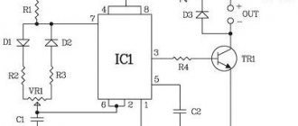
Device diagram
The simplest version of the circuit, designed to work with any load. Traditional electronic components are used, the control principle is phase-pulse.
Main components:
- triac VD4, 10 A, 400 V;
- dinistor VD3, opening threshold 32 V;
- potentiometer R2.
The current flowing through potentiometer R2 and resistance R3 charges capacitor C1 with each half-wave. When the voltage on the capacitor plates reaches 32 V, the dinistor VD3 opens and C1 begins to discharge through R4 and VD3 to the control terminal of the triac VD4, which opens to allow current to flow to the load.
The opening duration is regulated by selecting the threshold voltage VD3 (constant value) and resistance R2. The power in the load is directly proportional to the resistance value of potentiometer R2.
An additional circuit of diodes VD1 and VD2 and resistance R1 is optional and serves to ensure smooth and accurate adjustment of the output power. The current flowing through VD3 is limited by resistor R4. This achieves the pulse duration required to open VD4. Fuse Pr.1 protects the circuit from short circuit currents.
A distinctive feature of the circuit is that the dinistor opens at the same angle in each half-wave of the mains voltage. As a result, the current does not rectify, and it becomes possible to connect an inductive load, for example a transformer.
Triacs should be selected according to the load size, based on the calculation of 1 A = 200 W.
Elements used:
- Dinistor DB3;
- Triac TS106-10-4, VT136-600 or others, the required current rating is 4-12A.
- Diodes VD1, VD2 type 1N4007;
- Resistances R1100 kOhm, R3 1 kOhm, R4 270 Ohm, R5 1.6 kOhm, potentiometer R2 100 kOhm;
- Capacitor C1 0.47 µF (operating voltage from 250 V).
Note that the scheme is the most common, with minor variations. For example, a dinistor can be replaced with a diode bridge, or an interference-suppressing RC circuit can be installed in parallel with the triac.
A more modern circuit is one that controls the triac from a microcontroller - PIC, AVR or others. This circuit provides more accurate regulation of voltage and current in the load circuit, but is also more complex to implement.
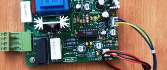
Triac power regulator circuit
Assembly
The power regulator must be assembled in the following sequence:
- Determine the parameters of the device on which the device being developed will work. Parameters include: number of phases (1 or 3), the need for precise adjustment of output power, input voltage in volts and rated current in amperes.
- Select the type of device (analog or digital), select elements according to load power. You can check your solution in one of the programs for modeling electrical circuits - Electronics Workbench, CircuitMaker or their online analogues EasyEDA, CircuitSims or any other of your choice.
- Calculate the heat dissipation using the following formula: voltage drop across the triac (about 2 V) multiplied by the rated current in amperes. The exact values of the voltage drop in the open state and the rated current flow are indicated in the characteristics of the triac. We get the power dissipation in watts. Select a radiator according to the calculated power.
- Purchase the necessary electronic components , heatsink and printed circuit board.
- Lay out contact tracks on the board and prepare sites for installing elements. Provide mounting on the board for a triac and radiator.
- Install the elements on the board using soldering. If it is not possible to prepare a printed circuit board, then you can use surface mounting to connect the components using short wires. When assembling, pay special attention to the polarity of connecting the diodes and triac. If there are no pin markings on them, then test them using a digital multimeter or a “dragstick”.
- Check the assembled circuit with a multimeter in resistance mode. The resulting product must correspond to the original design.
- Securely attach the triac to the radiator. Don’t forget to lay an insulating heat transfer gasket between the triac and the radiator. The fastening screw is securely insulated.
- Place the assembled circuit in a plastic case.
- Remember that there is dangerous voltage at the terminals of the elements.
- Turn the potentiometer to minimum and perform a test run. Measure the voltage at the regulator output with a multimeter. Smoothly turn the potentiometer knob to monitor the change in output voltage.
- If the result is satisfactory, then you can connect the load to the output of the regulator. Otherwise, it is necessary to make power adjustments.
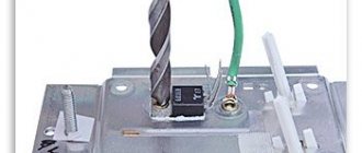
Triac power radiator
Power adjustment
The power control is controlled by a potentiometer, through which the capacitor and the capacitor discharge circuit are charged. If the output power parameters are unsatisfactory, you should select the resistance value in the discharge circuit and, if the power adjustment range is small, the potentiometer value.
Instructions on how to make a power regulator
Initially, we need to manufacture and prepare a printed circuit board for installation. There is no need to use special computer programs for this and print it with a laser printer on special paper. The circuit is not so complex that it requires the use of expensive equipment for its manufacture.
The easiest way is to make your own printed circuit board from a piece of PCB in the following sequence:
We cut off the required size, degrease and sand the surface. We create the outlines of the diagram with a pencil, then trace them with a marker. We perform etching with iron chloride to remove copper residues from the surface of the board.
We drill the necessary holes for the ends of the radio components. We wipe the manufactured board with liquid flux (rosin dissolved in alcohol). Using a thin layer of solder, we create current-carrying paths and pads.
- Certificate of conformity for equipment
How to choose a chicken coop?
Antenna for fm radio: how to make a model for a wide range of frequencies with your own hands. Step-by-step instructions with photos and videos!
When the board is ready, solder the following radio components into it:
- Microcontroller;
- Triac bta16;
- Dinistor db3;
- Resistor, 2 kOhm;
- Capacitor, 100 nF;
- Plate with pins.
We will also need a plug, cord and socket. And a box where the board with the microcircuit will be placed.
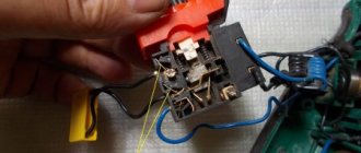
We install the dimmer in the following sequence:
We bite off and solder the pins (4 pcs.). We place all the parts except the microcontroller. We solder it thoroughly. Carefully clean the gaps between the current-carrying tracks using a needle and brush;
We drill a hole in the aluminum radiator. We attach a triac to it. Apply thermal paste KPT-8 to the surface of the radiator. We connect a variable resistor.
We close the middle and outer terminals with a piece of wire. We solder the wires to the extreme terminals. We connect the opposite ones to the board in the appropriate place.
Drive for sliding gates - choice of automation, the best materials for manufacturing and drive characteristicsDo-it-yourself power supply: step-by-step instructions on how to make a homemade, adjustable, universal and pulse model
Calculation of electrical cable cross-section: formulas, tables, online calculator for quick and accurate calculations
We take a socket with two wires connected to it. We solder one end of the core to the board. The other is to the power cord. We solder the remaining core (from the plug) to the board. We place all the collected “stuffing” in the box.
When the dimmer is assembled, we take a multiohmmeter in our hands and test the circuit. When everything is in order, connect the table lamp and rotate the knob on the device body to change its glow intensity. Its brightness will rise and fall depending on the direction of rotation.
If the lamp behaves as described, then the power regulator is made correctly and can be used for its intended purpose.
Power regulator on triac BTA12-600
Today I will tell you about a very useful scheme that will be useful both in the laboratory and on the farm. The device in question is called a triac power regulator. The controller can be used to smoothly adjust the brightness of the lighting, the temperature of the soldering iron, and the speed of the electric motor (AC). My version of using the regulator is more interesting; I smoothly regulate the heating temperature of a 1 kW heating element in a moonshine still. Yes, yes, I am doing this noble work.
The circuit has a minimum of elements and starts up immediately. The load power for a triac regulator is determined by the triac current. The BTA12-600 triac is designed for a current of 12 Amps and a voltage of 600 Volts. The triac must be selected with a current reserve; I chose a double reserve. For example, a BTA12-600 triac with optimal cooling can pass a current of 8 Amps through itself in normal mode. If you need a more powerful regulator, use a triac BTA16-600 or BTA24-600.
The operation of the circuit is described in the article “DIY Dimmer”.
The operating temperature of the triac crystal is from -40 to +125 degrees Celsius. Good cooling is necessary. I have a load of 1 kW, respectively, the load current is about 5A, a radiator with an area of 200 cm2. Heats up from 85 to 90 degrees Celsius during long-term operation (up to 6 hours). I plan to increase the working area of the radiator to increase the reliability of the device.
The triac has a control terminal and two terminals through which the load current passes. These two conclusions can be swapped, nothing bad will happen.
For safety (so that the current does not click), the triac must be installed on the radiator through a dielectric gasket (polymer or mica) and a dielectric bushing.
Components.
Resistor 4.7 kOhm with a power of 0.25 W. The dinistor marked DB3 has no polarity, solder in either direction. A 100nF 400V film capacitor has no polarity.
LED of any color with a diameter of 3mm, reverse voltage 5V, current 25mA. In short, any 3mm LED. The LED gives an indication of the load; do not be alarmed if when you turn it on for the first time (of course without a load), it does not light up.
The first switch-on must be done briefly without load. If everything is normal, no elements heat up, nothing clicks, then turn it on without load for 15 seconds. Next, we connect a lamp with a voltage of 220V and a power of 60-200W, turn the variable resistor knob and enjoy the work.
For protection, I installed a 12A fuse in the break in the power cable (220V).
The power regulator we assembled on the BTA12-600 triac can be used to adjust the temperature of the soldering iron (by adjusting the power), thereby obtaining a soldering station for your workshop.
Printed circuit board for power regulator based on triac BTA12-600
Datasheet for BTA12-600
DIY power regulator photo
- External tiling work - features and unusual solutions
DIY welding machine: simple instructions for creating and using the device
Wall-mounted curtain rods: mounting options, review of modern models
Read here! How to determine phase and zero - step-by-step instructions for determining and choosing the optimal tool