Most rotary electronic hairpieces use a commutator motor. It allows you to obtain the high starting torque necessary in some cases. The principle of its operation is based on the rotation of the rotor under the influence of the magnetic field of the stator, to which voltage is applied.
In order to obtain a suitable rotation speed without loss of power, a rotation speed control device is required. Therefore, this article will discuss how to make an engine speed controller with your own hands.
Difficulties and features
The difficulty in creating a speed controller for a commutator motor lies in the fact that the device consumes not only active, but also reactive power, which increases with increasing speed. The main task is to align and reduce the gap between these two characteristics.
The power of a commutator motor is the product of the current it consumes and the network voltage. Its general meaning consists of active and reactive.
At home it is quite difficult to reduce empty losses to zero. To do this, it is necessary that the device experiences only an active load, which can only be achieved by using semiconductor resistors.
Selection criteria and cost
In order to correctly choose the most suitable type of regulator, you need to have a good idea of what types of such devices there are:
- Various types of control. Can be a vector or scalar control system. The former are used more often, while the latter are considered more reliable.
- The power of the regulator must correspond to the maximum possible power of the motor.
- Based on voltage, it is convenient to choose a device that has the most universal properties.
- Frequency characteristics. The regulator that suits you should match the highest frequency that the motor uses.
- Other characteristics. Here we are talking about the length of the warranty period, dimensions and other characteristics.
Depending on the purpose and consumer properties, prices for regulators can vary significantly.
For the most part, they range from approximately 3.5 thousand rubles to 9 thousand:
- Speed controller KA-18 ESC , designed for 1:10 scale models. Costs 6890 rubles.
- MEGA speed controller is manifold (waterproof). Costs 3605 rubles.
- Speed controller for LaTrax 1:18 models. Its price is 5690 rubles.
Source
Principle of operation
For assembly, it is best to choose a thyristor converter; it will allow you to change the operating mode without significant losses.
In addition, thanks to it, functions such as:
- Acceleration-braking.
- Tight control of characteristics.
- Switching to reverse movement.
In addition, it has pulse-phase control. Which allows you not to lose rotor torque without increasing losses in the reactive characteristic.
The speed controller circuit will consist of the following key components:
- Controlled signal rectifier.
- Control unit.
- Feedback system.
- Network power regulator.
How to make a homemade engine speed controller
You can make a simple triac motor speed controller, its diagram is presented below, and the price consists only of parts sold in any electrical store.
To work, we need a powerful triac of the BT138-600 type, it is recommended by a radio engineering magazine.
Photo - do-it-yourself speed controller diagram
In the described circuit, the speed will be adjusted using potentiometer P1. Parameter P1 determines the phase of the incoming pulse signal, which in turn opens the triac. This scheme can be used both in field farming and at home. You can use this regulator for sewing machines, fans, tabletop drilling machines.
The principle of operation is simple: at the moment when the motor slows down a little, its inductance drops, and this increases the voltage in R2-P1 and C3, which in turn leads to a longer opening of the triac.
A thyristor feedback regulator works a little differently. It provides energy back into the energy system, which is very economical and profitable. This electronic device involves the inclusion of a powerful thyristor in the electrical circuit. His diagram looks like this:
Here, to supply direct current and rectify, a control signal generator, an amplifier, a thyristor, and a speed stabilization circuit are required.
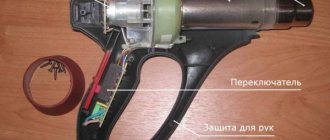
Almost all household appliances and power tools use a commutator motor. Newer models of grinders, screwdrivers, hand routers, vacuum cleaners, mixers and others have engine speed control, but later models do not have this function. It is not always convenient to work with such tools and household appliances, and therefore there are speed controllers with power maintenance.
Types of engines and operating principles
Motors are divided into three types: commutator, asynchronous and brushless. Most power tools use the first type. This electric motor has a fairly compact size. Its power is significantly higher than that of asynchronous, and the price is quite low. As for asynchronous ones, this type is mainly used in the metalworking industry, and they are also widespread in coal mines. Quite rarely they can be found in everyday life.
The brushless electric motor is used where high speeds, precise positioning and small dimensions are needed. For example, in various medical equipment, aircraft modeling. The principle of operation is quite simple. If a rectangular frame, which has an axis of rotation, is placed between the pluses of a permanent magnet, then it will begin to rotate. The direction depends on the direction of the current in the frame. This type contains an armature and a stator. The armature rotates, but the stator stands still. As a rule, there is not one frame at anchor, but 4.5 or more.
An asynchronous motor works on a different principle. Thanks to the effect of an alternating magnetic field in the stator coils, it is driven into rotation. If you delve deeper into the course of physics, you can remember that a kind of magnetic field is created around the conductor through which the current passes, causing the rotor to rotate.
The principle of operation of the brushless type is based on turning on the windings so that the magnetic fields of the stator and rotor are orthogonal to each other, and the torque is regulated by a special driver.
The figure clearly shows that in order to move the rotor it is necessary to perform the necessary commutation, but it is not possible to regulate the speed. However, the brushless motor can rev up very quickly.
Regulator
Having finished with the engine and having understood its performance and operating mode, you can make a speed controller for an asynchronous motor with your own hands.
The following goals must be achieved:
- The adjustment should be carried out from zero revolutions to the maximum possible values.
- At low speeds the torque should be highest.
- It is necessary to achieve a smooth change in the number of revolutions.
Scope of regulators
A simple example of such a converter is a voltage stabilizer, often used in everyday life. However, in comparison with it, the speed controller is more functional. Frequency converters are widely used and are used in all electrical devices. Their use not only provides precise control over engine operation,
but electrical energy savings are also achieved, since the power plant consumes only the necessary power, and not the maximum.
You can buy an engine speed controller without loss of power to solve the following problems:
- Motor temperature control without the use of additional controllers.
- Maintenance costs are reduced.
- Smooth start is ensured.
- Electrical energy is saved.
The device is used in all household appliances, welding machines, etc.
Connection features
When connecting wires and connecting the main components to each other, you should adhere to the following recommendations:
- The wires should not be too long. Especially when it comes to the speed controller of a brushless motor.
- The winding must not be damaged.
- The connection points must be securely sealed and insulated from each other.
DIY bumper: how to make a unique polymer bumper for a car at home (125 photos)Do-it-yourself car painting - preparation for coating and the main stages of high-quality car painting (100 photos)
Polishing a car with your own hands - a step-by-step master class on how and how to polish a car’s paintwork (70 photos)
12V commutator motor speed stabilizer
The speed stabilizer circuit (like other similar ones) is based on receiving a signal proportional to the rotation speed
There are two main differences:
— to isolate a voltage proportional to the rotation speed of the armature, a bridge circuit is used, which allows to select a voltage of the rotor back-EMF proportional to the rotation speed
Next, the resulting voltage Uoc can be used for feedback of essentially any power source.
In the described diagram, the bridge looks like this
Subject to the proportion R1/R2 = R3/Rya (Rya is the armature resistance) and at Uos = 0, we will receive compensation Rya and, accordingly, E of the rotor back-EMF will be equal to the stabilization voltage VD1
If VD1 is made adjustable, then, in essence, by changing its stabilization voltage, we change the voltage directly on the engine rotor (compensating for the influence of Rya) and ensure stability of the rotation speed.
In this case, the TNY268P was taken as a basis in a standard connection circuit (according to the datasheet)
The part of the circuit to the left of the transformer is the standard TNY268 harness (essentially, any UPS design with the widest possible output voltage range (this range determines the range of rotor speed changes) and the required power can be used as a basis.
On the right side of the diagram, the bridge itself is formed by resistors R5, R6 and R9 (similar to R1, R2 and R3 in the diagram in the middle figure).
VT1, VT2 and a string of resistors R3, R4, R7 form an analogue of a zener diode with an adjustable stabilization voltage (can be replaced with TL431).
Actually Uoc appears between the base and emitter VT3, which controls the LED current in optocoupler U2, creating feedback.
VD8 is introduced as a base-emitter voltage compensator for VT3. Capacities C9 and C10 give stability to the feedback node.
The VD9 zener diode limits the maximum voltage at the output of the power supply and, with built-in overvoltage protection, is not needed.
When preparing a circuit for a specific electric motor model, it is possible that the rating of R5 will be different (to maintain the proportion R5 / (0.7 * R6) = R9 / Rya. The voltage drop across R9 at the rated current consumption should be about 1V, more is undesirable - it will get very hot.
Step-by-step instruction
The classic sinistor circuit works on the principle of charging a capacitor through a low-capacitance resistor. After the voltage between the plates reaches the desired value, the triac begins to pass current to the load.
In this way, you can control the capacitance of the capacitor by changing the voltage that goes to the load. A rheostat, which is installed in place of the resistor, is perfect for this.
Unfortunately, such a circuit heats up quickly, which is why it is necessary to install an additional radiator to effectively remove heat.
A more suitable circuit that allows you to save lost power and more accurately control operation is switching with power resistors. Their work is based on repeated opening and closing of an electrical sinusoid in one period.
This installation can operate from an internal storage device with a voltage of 12 V and an external one of 220 V. However, in this case, a quenching circuit is required.
In this operating mode, you can change the threshold power, this directly affects the power of the rotor. Power resistors are set to specific readings of the incoming current, collecting it in the required volumes.
Polishing headlights with your own hands - how and how to properly polish headlights at home (100 photos)Replacing thresholds with your own hands - advice from professionals on repairing the bottom and thresholds (120 photos)
Do-it-yourself carburetor adjustment - 120 photos and tips on how to properly set up and check the unit
Is it easier to buy a dimmer?
They reduce its size and, accordingly, power consumption. According to the Joule-Lenz and Ohm laws for an electrical circuit. Effective control of load power is provided by special technical solutions. And any power regulator circuit contains a semiconductor switch. Anyone who wants to quickly gain the ability to flexibly control their electrical appliances can easily buy a simple power regulator. It is a dimmer. Various models of this device are sold in retail chains.
Such a regulator is very convenient in the country. It will be a wonderful addition to a small boiler or one- or two-burner electric stove. Now during cooking there will be no burning and too much boiling.
When buying a power regulator, be sure to make sure that it suits the tasks being solved. It must be more powerful than the electrical equipment being controlled. Most dimmer models are designed for servicing apartment lighting. For this reason, they mainly regulate power up to 300W.
Didn't find it in the store - do it yourself
To purchase a more powerful model, you will have to look for it in retail chains. An alternative solution is to look at power regulator diagrams and make the selected model yourself. To help our readers choose the optimal circuit, we will describe in more detail the main features of these devices. The controller on a semiconductor switch can be made using
- bipolar transistor;
- field effect transistor;
It will be interesting➡ How to check the zener diode for performance
- thyristor;
- symmetrical thyristor (triac, triac).
A power regulator, the circuit of which contains any of the listed semiconductor switches, is always in one of two states. It either limits the current as much as possible (disconnects the load) or provides almost no resistance (connects the load).
When triggered, the junction resistance of semiconductor devices quickly changes in value. Each value corresponds to a certain electrical power. It is released as heat and is called dynamic losses. The faster the device operates (disconnects or connects the load), the lower the dynamic losses.
The fastest switches are transistors. But they turn on and off at any non-zero voltage value. If these processes occur near its amplitude value, the dynamic losses will be as large as possible. A conventional thyristor switch differs in that it turns off without a control signal when the load current passes through zero. Although it is turned on at the same amplitude of the alternating voltage as that of transistors.
Choose a triac
For this reason, the thyristor circuit, and especially the triac power regulator, turns out to be simpler, more economical and reliable. Especially if it turns on quickly. The power regulator on the triac, apart from it, has no more semiconductor devices through which the load current flows. And regulators with other switches and such devices will definitely have rectifier diodes, including built-in ones.
Therefore, we recommend focusing on triacs - circuits with them are in many reference books, popular magazines and, consequently, on the Internet. They are easy to find and choose something acceptable. The first power regulator based on the KU208G triac has been used for many years, starting in the 80s of the last century.
Modern triacs in regulators
The outdated design of the KU208G is not always convenient for placement in the regulator body. The new model BT136 600E, which has approximately the same switching and adjustment parameters, will allow you to assemble a more compact triac power regulator. With this model, due to its compact size, there are significantly more design options from which to choose.
This is interesting! All about semiconductor diodes.
If you make your own power regulator, the diagram of which is taken from any source, be sure to compare the maximum currents of the switch used and the load. For these purposes, divide the rated load power by 220. For reliable operation of the power regulator on a triac and not only the resulting current value must be 0.7 from the rated value of the switch used in the circuit. Therefore, for many household electrical appliances the KU208G will be rather weak. But it can be replaced with a more powerful one, for example VTA 12.
This key with its 12 amperes will be able to reliably regulate the load up to 1848 W with a short increase to 2000 W. The assembled power regulator on a triac of this model, for example, can be used to control an electric kettle. One such option is shown below.
When choosing a power regulator circuit:
- commutator DC motor,
- universal (also commutator) engines,
- suitable for controlling an electric motor in any electrical equipment,
We recommend paying attention to control safety. It is provided by galvanic isolation in the regulator circuit. The key is reliably released from the control element that the user touches. For this purpose, circuit solutions with transformers, as well as optocoupler electronic devices, are used. Examples of such schemes are shown below. In these schemes, the control element is part of the controller.
An effective, reliable and safe power regulator will add new consumer properties to many of your electrical appliances. You are left with the right choice of device when purchasing or making them without errors with your own hands according to the chosen scheme.