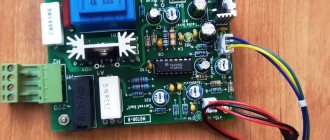
Today it rained all day, and in order not to sit at home, I sat in the garage =) I turned on the air compressor using improvised means.
There was also a receiver, I don’t remember where I got it from
I bought everything else needed in the store - Pressure switch RDM-5...439.90 rub. — Tape-fum...29.90 rub. — Adapter 1″*1/2″…64.90 rub. — Fitting 10*1/2″…48.90 rub. — Five-way valve for the VR-NR pump...249.90 rub. — Pressure gauge...199.90 rub.
The connection diagram is very simple
I won’t describe the assembly process, I think everything is clear, I’ll just show you what happened =)
I started it to check, it turned out that it pumps up to 3.5 bar - it turns off, then drops to 2 bar - it turns on. 1 bar = 0.987 standard atmosphere
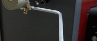
I welded the frame, all that remains is to paint it and buy a moisture separator and gearbox.
Total: 1033 rub. well, + a moisture separator (I don’t know how much it costs yet)
Now you can learn how to aerogrify =)
In general, as requested, the measurement in the relationship of time and pressure turned out like this:
0.5bar - 34 sec. 1bar - 1 min. 13 sec. 1.5 bar - 1 min. 53 sec. 2 bar - 2 min. 35 sec. 2.5 bar - 3 min. 18 sec. 3 bar - 4 min. 9 sec. 3.5 bar - 5 minutes
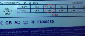
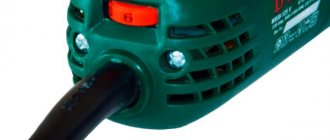
Regarding which tube on the compressor goes where, I have a compressor from the Biryusa-14 refrigeration chamber, compressor marking: HKV5-1LB UHL
Budget air compressor models do not always have an air pressure switch in their design, because the same devices are installed on the receiver. For this reason, companies producing this equipment believe that visual pressure monitoring through pressure gauges is sufficient. However, during long-term work, to protect against overheating, it is better to install a pressure regulator for the compressor, which will automate the switching on and off of the drive.
Purpose
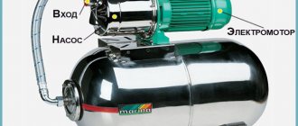
The operation of any air compressor involves producing a stream of air. It must be of a certain pressure, stable and uniform. It must be possible to change the parameters of the air stream. Any compressor has an air reservoir (a container in the form of a cylinder). It must contain the required pressure. If it starts to fall, you need to turn on the engine and replenish the air supply.
If the pressure becomes excessive, it is necessary to stop the supply of air mass. Otherwise, the tank will simply burst. It is the relay and pressure regulator that control this process. The high-quality operation of this mechanism ensures the safety of the engine, protects it from frequent switching on and off, and makes the operation of the system uniform. The reservoir membrane is structurally connected to the relay switch. By moving, it turns the relay on or off.
Alexstut › Blog › Automation for garage compressor
We were lucky to save a Soviet-made two-cylinder compressor from ferrous metal. Externally similar to S412M. But we got the compressor itself without trim, chassis, or engine. Over the course of some time, I collected everything into a pile.
Comments 2
Here is all the information a beginner or an experienced compressor operator needs)))
Let's start by converting a crap foam filter into a normal paper filter from cars of all brands.
Installing the Scatter Filter on Metabo 250-50 W
also a filter
KU KU smart guys! Why would you recommend disposable high-quality Chinese consumer goods to a person? Why would he suffer later? Go advise your enemy! I have already recommended which compressor to buy!
And this is a purebred Italian - ABAC. It does not stink of Chinese paint and chloride plastic. His video review 1)
Remaking its filter 2) Repairing it and T.O. 3) 4) 5) Checking and tensioning the belt. Please pay attention to the well-thought-out and high-quality casing, which directs all the air to cool the compressor head. And not some kind of shitty steel grille like the Ketayts have. Which directs the air anywhere but to cool the head. Replacing head gaskets Installing piston rings on such a compressor head And excellent videos about those. maintenance of such 2-cyl. compressors
It has a clever air cooling system thanks to an interesting casing ia.d-cd.net/E0AAAgKlyOA-1920.jpg
Even though he is Italian, he has one horseradish regular shit foam filter(((
photo of a twisted nozzle: i.ebayimg.com/images/g/Qb…AAOSwspdaqJUe/s-l1600.jpg good video review of it:
And here is an example of a person’s crookedness in handling such a pistol. soda, damn it, he uses)) sugar or table salt should have been used.
Source
Connection
The question is always relevant and important: “How to connect a relay correctly, without errors?” You can connect this device yourself if you have serious electrical and commissioning skills. But it is better to take the help of a competent specialist. Connecting a pressure switch requires attention and vigilance. When replacing and connecting, you need to know exactly what voltage is in your network: 220V or 380V.
The connection diagram of the relay to the compressor involves several important points. The relay works on the principle of comparing the magnitude of air pressure forces. To set up this device, you must first record the on and off pressure using a pressure gauge. Then disconnect the electrical power.
Read also: Two-key switch Schneider electrician how to connect
Any relay in its design has adjusting screws. With their help, the amount of air flow at which the device operates is selected. Several combinations are performed, each of which is accompanied by the start of the compressor. The usual principle of selecting the most optimal, accurate option works. The connection and configuration diagram can be standard, or it can be developed independently.
Connection and setup
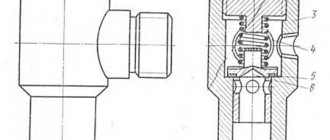
The general diagram of the compressor installation shows that the pressure switch is located between the unload valve and the secondary control circuit. Most often, a pressure switch for a compressor has four threaded heads, one of which connects the device to the receiver, and the other connects a pressure gauge to monitor readings. The third can be fitted with a safety valve, and the last has a quarter-inch threaded plug in the thread. With a free connector, the user can install a control pressure gauge at his discretion.
Read also: Head of the traffic police department of the Russian Ministry of Internal Affairs for the Bryansk region
The pressure switch is connected according to the following sequence:
- The device is connected to the unloading valve of the receiver.
- Install a control pressure gauge or plug.
- The engine control circuits are connected to the contacts.
- If there are fluctuations in the voltage network, then the connection is made through a surge filter, including when the contact power is greater than that available for the motor load current.
- If there is a need for this, the relay is adjusted through the adjustment screws to the required air pressure.
The connection is accompanied by checking that the voltage in the network matches the factory settings of the pressure switch. For example, a three-phase network of 380 Volts requires the use of a three-contact group, and for 220 Volts a two-phase group must be used.
The adjustment is made when the receiver is at least two-thirds full. The relay is disconnected from the network, the top cover is removed and the compression of the two springs is changed. The operating pressure limit is determined by an adjusting screw with an axis of larger diameter. On the board next to it there is a pressure mark in the form of the letter P and an indication of the direction of rotation of the screw, with the help of which the specified parameter is changed. The second screw helps set the required difference ΔP and has an indicator in which direction it rotates.
To speed up the adjustment process , in some cases the adjusting screw is pulled out, which changes the upper pressure level.
Control is carried out according to the readings of the pressure gauge on the pressure regulator for the compressor.
Handicraft production
Making a relay yourself in a garage is very difficult. You must have ingenious knowledge and possess complex technologies in your workshop. The operation of the device is based on the principle of operation of the mechanism when electric current passes through special elements. These elements, at a certain current value, heat up, turning the mechanism on or off. Even an experienced electrician will find it difficult to make such a mechanism. When making a homemade compressor, old refrigerators are used, which always have their own relay.
I made and adjusted the air pressure switch for the compressor myself: find out how
The Russian market offers potential consumers a large number of different tools. Analyzing the state of the market, experts note a slight increase in the popularity of pneumatic tools. However, while surpassing traditional types of power tools in basic parameters (power, reliability, durability), pneumatic tools require a source of compressed air. Such a source is an air compressor, the purchase of which for one-time work is not economically feasible. That is why, widely used by professionals, pneumatic tools are rarely used in everyday life.
It is this device that regulates the air pressure in the compressor
- Pressure switch: purpose and principle of operation
- DIY pressure switch
- Relay malfunctions and their elimination
Structurally, an air compressor is a device that can be manufactured by a person who has certain knowledge and skills in performing plumbing and electrical work at home. The responsible unit is an air pressure switch (pressostat), which you can install and adjust yourself. In addition, you can independently eliminate the simplest malfunctions of the pressure switch.
Acquisition
The air compressor relay operates under difficult conditions, it is subject to wear and tear and may fail. Repair is a very difficult and unprofitable business. It is more profitable to replace the device with a completely new one. There is no point in designing it yourself if you can buy it. The minimum average price is 600 - 800 rubles. There are expensive options from branded manufacturers, but they cost an order of magnitude higher. If you have that kind of money, then it’s easier to buy a completely new compressor.
One of the main indicators of air compressors is operating pressure. In other words, it is the level of air compression created in the receiver that must be maintained within a certain range. It is inconvenient to do this manually, referring to the indicators of the pressure gauge, so the compressor automation unit is responsible for maintaining the required level of compression in the receiver.
How to connect and configure a pressure switch?
In the general circuit diagram of a compressor installation, the pressure switch is located between the unloader valve and the secondary engine control circuit. Typically the pressure switch is equipped with four threaded heads. One of them is intended for connecting the device to the receiver, and the second is for connecting a control pressure gauge. One of the remaining connectors can be used to install a safety valve, and the remaining one can be fitted with a regular ¼-inch threaded plug. The presence of a free connector allows you to install the control pressure gauge in a place convenient for the user.
The pressure switch is connected in the following sequence:
- Connect the device to the unloading valve of the receiver.
- Install a control pressure gauge (if it is not necessary, then the threaded inlet is also plugged).
- Connect the terminals of the electric motor control circuit to the contacts (taking into account the selected connection diagram - to normally open or normally closed contacts). When the voltage in the network fluctuates, the connection is made not directly, but through a surge protector. This is also required when the power for which the contacts are designed exceeds the motor load current.
- If necessary, use the adjusting screws to adjust the relay to the required compressed air pressure values.
When connecting, you need to check whether the network voltage corresponds to the factory settings of the compressor pressure switch.
For example, in a three-phase network with a voltage of 380 V, the relay must have a three-contact group (two phases + zero), and for a voltage of 220 V - a two-contact group. The adjustment is made when the receiver is at least two-thirds full. To perform this operation, the relay is disconnected from the power supply, and, by removing the top cover, the compression of the two springs is changed. The adjusting screw, on which the axis of the larger diameter spring is mounted, is responsible for the upper limit of the working pressure. On the board next to it, the generally accepted pressure symbol (P - pressure) is usually indicated, and the direction of rotation of the screw by which this pressure is reduced or increased is also indicated. The second, smaller adjustment screw is responsible for setting the required pressure range (difference). It is marked with the symbol ΔР, and is also equipped with an indicator of the direction of rotation.
To reduce setup time, in some designs the adjusting screw for changing the upper pressure limit is moved outside the pressure switch housing. The result is monitored using the pressure gauge readings.
Design and principle of operation of the automation unit
To maintain the pressure in the receiver at a certain level, most air compressors have an automation unit, a pressure switch.
This piece of equipment turns the engine on and off at the right time, preventing the compression level in the storage tank from being exceeded or too low.
The pressure switch for the compressor is a unit containing the following elements.
- Terminals. Designed for connecting electrical cables to relays.
- Springs. Installed on adjusting screws. The pressure level in the receiver depends on the force of their compression.
- Membrane. It is installed under the spring and compresses it under the action of compressed air.
- Power button. Designed to start and force stop the unit.
- Connection flanges. Their number can be from 1 to 3. The flanges are designed for connecting the compressor start relay to the receiver, as well as for connecting a safety valve with a pressure gauge to them.
In addition, automation for the compressor may have additions.
- Unloading valve. Designed to relieve pressure after a forced stop of the engine, which makes it easier to restart.
- Thermal relay. This sensor protects the motor windings from overheating by limiting the current.
- Time relay. Installed on compressors with a three-phase motor. The relay turns off the starting capacitor a few seconds after the engine starts.
- Safety valve. If the relay malfunctions and the compression level in the receiver rises to critical values, then in order to avoid an accident, the safety valve will operate, releasing the air.
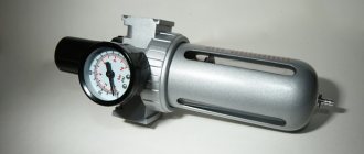
- Gearbox. Pressure gauges are installed on this element to measure air pressure. The reducer allows you to set the required level of compression of the air entering the hose.
The operating principle of the pressure switch is as follows. After the compressor engine starts, the pressure in the receiver begins to increase. Since the air pressure regulator is connected to the receiver, the compressed air from it enters the membrane relay unit. The membrane bends upward under the influence of air and compresses the spring. The spring, compressing, activates the switch, which opens the contacts, after which the engine of the unit stops. When the compression level in the receiver decreases, the membrane installed in the pressure regulator bends down. At the same time, the spring opens, and the switch closes the contacts, after which the engine starts.
Self-production of pressure switches
Having the skills and a working thermostat taken from a decommissioned refrigerator allows you to independently create a pressure switch for the compressor. But at the same time, it will not have practical application due to the inability to hold the upper bar for a long time. After all, the strength of a rubber bellows is very limited.
It is most convenient to remake the KTS 011 thermal relay. They have a strictly reverse operation sequence. This means that the relay turns on when the temperature in the refrigerator rises, and turns off when the temperature drops.
The sequence of actions during the work is as follows:
- Establish the location of the corresponding contacts by testing the circuit.
- You are finalizing the connection of the thermal relay with the compressor, for which the pipe and pressure gauge are connected to the valve, and the contacts are connected to the motor circuit terminals.
- There is an adjustment screw under the cover. Turning on the compressor is accompanied by sequential rotation with monitoring of the readings on the pressure gauge.
- Setting the lower position allows you to gradually move the face button rod.
- The cover is installed in place; it has to be adjusted blindly due to the lack of space for a second pressure gauge.
For safety, the pressure regulation interval on such a thermostat is from 1 to 6 atmospheres. But when using devices with a reinforced bellows, the upper range is increased to 10 atmospheres, which is often sufficient.
When the functionality of the relay has been checked, you need to cut off the capillary tube and remove the accumulated refrigerant from there. The end of the tube is soldered into the unloading valve.
Then you need to take steps to connect a self-made pressure switch to the compressor control circuit. We attach the relay to the control board with a nut and cut a thread on the rod. Then we screw on the locknut to regulate the limits of air pressure change.
Taking into account the fact that the group of contacts of any such relay from a refrigerator is designed for very significant currents, high-power circuits are switched using this method, including secondary compressor motor control circuits.
The device described above is a very important element for any device. With its help, the operation of the electric motor drive is regulated. A home-made relay is not particularly practical, but using a reinforced bellows, you can increase the pressure range and improve the performance of the device. It also allows you to switch high-power circuits like secondary circuits to control the compressor motor.
The Russian market offers potential consumers a large number of different tools. Analyzing the state of the market, experts note a slight increase in the popularity of pneumatic tools. However, while surpassing traditional types of power tools in basic parameters (power, reliability, durability), pneumatic tools require a source of compressed air. Such a source is an air compressor, the purchase of which for one-time work is not economically feasible. That is why, widely used by professionals, pneumatic tools are rarely used in everyday life.
Read also: Volkswagen transporter will not start
It is this device that regulates the air pressure in the compressor
Structurally, an air compressor is a device that can be manufactured by a person who has certain knowledge and skills in performing plumbing and electrical work at home. The responsible unit is an air pressure switch (pressostat), which you can install and adjust yourself. In addition, you can independently eliminate the simplest malfunctions of the pressure switch.
Diagrams for connecting the pressure switch to the compressor
The connection of the relay that controls the degree of air compression can be divided into 2 parts: the electrical connection of the relay to the unit and the connection of the relay to the compressor through the connecting flanges. Depending on which motor is installed in the compressor, 220 V or 380 V, there are different connection diagrams for the pressure switch. I am guided by these diagrams, provided that you have certain knowledge in electrical engineering, you can connect this relay with your own hands.
Read also: Micrometer purpose and device
Connecting the relay to a 380 V network
To connect the automation to a compressor operating from a 380 V network, use a magnetic starter. Below is a diagram of connecting automation to three phases.
In the diagram, the circuit breaker is indicated by the letters “AB”, and the magnetic starter by “KM”. From this diagram it can be understood that the relay is set to a switch-on pressure of 3 atm. and shutdown - 10 atm.
Connecting the pressure switch to a 220 V network
The relay is connected to a single-phase network according to the diagrams given below.
These diagrams indicate various models of pressure switches of the RDK series, which can be connected in this way to the electrical part of the compressor.
Connecting the pressure switch to the unit
Connecting a pressure switch to a compressor is quite simple.
- Screw the pressure switch onto the receiver pipe using its central threaded hole. For better thread sealing, it is recommended to use fum tape or liquid sealant. The relay can also be connected to the receiver through a reducer.
- Connect a relief valve to the smallest output from the relay, if present.
- The remaining outputs from the relay can be connected to either a pressure gauge or a safety relief valve. The latter is installed without fail. If a pressure gauge is not required, then the free output of the pressure switch must be plugged with a metal plug.
- Next, wires from the electrical network and from the engine are connected to the sensor contacts.
After the complete connection of the pressure switch is completed, it is necessary to configure it for proper operation.
DIY pressure switch
Having taken on the task of making an air compressor on their own, some amateur craftsmen may decide to make a pressure switch with their own hands.
Making your own equipment is interesting, practical and very economical
On the Internet you can find options for homemade devices, for example, made from a thermostat from a refrigerator or made using parts from CDs and plastic bottles. However, it should be noted that their design cannot be compared with the design of a commercially produced compressor pressure switch. In addition, the use of a homemade device, in the event of a sudden failure, can lead to an emergency with unpredictable consequences for others.
TIP: given that the air pressure switch is one of the most critical components of the compressor, it is better to install an industrial pressure switch even in a homemade compressor.
Adjusting the compressor pressure
As mentioned above, after creating a certain level of air compression in the receiver, the pressure switch turns off the unit’s engine. Conversely, when the pressure drops to the switching limit, the relay starts the engine again.
Important! By default, relays, both single-phase devices and units operating from a 380 V network, already have factory settings. The difference between the lower and upper engine start threshold does not exceed 2 bar. It is not recommended for the user to change this value.
But often situations that arise force you to change the factory settings of the pressure switch and adjust the pressure in the compressor at your discretion. You can only change the lower switching threshold, since after changing the upper switching threshold upward, the air will be released by the safety valve.
Pressure adjustment in the compressor is carried out as follows.
- Turn on the unit and record the pressure gauge readings at which the engine turns on and off.
- Be sure to disconnect the device from the power supply and remove the cover from the pressure switch.
- After removing the cover, you will see 2 bolts with springs. The large bolt is often designated by the letter “P” with the signs “-” and “+” and is responsible for the upper pressure, upon reaching which the device will be turned off. To increase the level of air compression, turn the regulator towards the “+” sign, and to decrease it, turn towards the “-” sign. First, it is recommended to make half a turn with the screw in the desired direction, then turn on the compressor and check the degree of pressure increase or decrease using a pressure gauge. Record at what indicators of the device the engine will turn off.
- Using a small screw you can adjust the difference between the on and off thresholds. As mentioned above, it is not recommended that this interval exceed 2 bars. The longer the interval, the less often the device’s engine will start. In addition, the pressure drop in the system will be significant. Setting the on-off threshold difference is done in the same way as setting the upper on-off threshold.
In addition, you need to configure the gearbox if it is installed in the system. It is necessary to set the compression level on the gearbox to a level that corresponds to the operating pressure of the pneumatic tool or equipment connected to the system.
Circuit and device
The device is divided into the following types:
- Starting the electric motor of the compressor when the pressure drops below the set value (normally closed);
- Switching off the engine when the air pressure rises above the normal level (normally open).
The executive element in the device is springs. Their compression force is measured using a special screw. As a rule, manufacturers adjust the compression force of the springs so that the pressure in the pneumatic network is in the region of 4-6 at. This parameter is always precisely indicated in the instructions.
Since the flexibility and stiffness of springs always largely depends on temperature, all elements of industrial pressure switches are designed and created taking into account subsequent operation at temperatures from minus 5 to plus 80 degrees.
The pressure switch includes 2 mandatory subassemblies in its design - a mechanical switch and a relief valve. A mechanical switch protects against accidental starting of the engine, thus performing the stand by function. After pressing, the device drive starts, after which the compressor begins to operate in automatic mode. Without pressing the button, the electric motor will not work even with reduced pressure in the pneumatic network.
The unloading valve is connected to the air supply line between the compressor and the receiver and is responsible for engine operation. When the compressor drive is turned off, the unloader valve on the receiver gets rid of excess compressed air, thus relieving the moving parts of the extra effort required when restarting the compressor. This eliminates overloading of the engine during torque. When the unloaded engine is turned on, the valve closes, which prevents unnecessary load from being created.
For greater safety, the pressure switches are additionally equipped with safety valves, which turn out to be very useful, for example, in case of piston failure, sudden stop of the electric motor and in any other emergency situation!
A thermal relay can also be installed in the pressure switch housing, allowing you to monitor the current strength in the primary circuit. When this parameter is increased, the thermal relay will automatically turn off the engine, thus protecting the device from overheating and breakdown of the windings.
Communities › Garage Equipment and Tools › Blog › DIY garage compressor. My version.
I’ve been reading community threads on garage equipment and tools for a long time. I note quite active interest of people in this topic.
So I decided to share my version of self-propelled gun.
For some time I wandered around the shops, studying the prices and offers of Chinese factory equipment, and the idea came to me to build a compressor, using - at the same time - components: both purchased ones, THOSE IT IS BETTER TO BUY READY-MADE, and those made independently or modified with my own hands. The result is to get a more or less decent tool at a reasonable price for its parameters. Therefore, I’ll make a reservation right away: this post is not about how to hack the system and get a canary for a penny!
. This is most likely an illustration of the idea of saving a little money by monetizing your love for hands-on technical creativity)))
So, to begin with, I got my hands on a 50 liter propane cylinder.
It should be noted here that I had to work a little to wash its insides from the remnants of the odorant - it is well known that a mixture of natural mercaptans is added to natural gas, which gives the gas its odor. Getting rid of the smell in the cylinder turned out to be a very difficult task.
Repeated washing with water helped very little, although it removed the main nastiness in the form of fatty deposits.