How to reduce the power of a soldering iron
Many people are familiar with an inexpensive soldering iron from Aliexpress with a built-in voltage regulator. A dimer is better than nothing, but it does not provide normal operation with a soldering iron. At one time, L. Elizarov from Makeevka, Donetsk region, published a diagram of a temperature stabilizer for a soldering iron without a sensor. By measuring the change in resistance of the heating element. The diagram has been published many places. There was another article in Radio magazine.
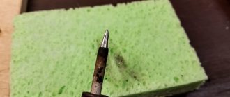
Some time ago I already used the first circuit for a soldering iron with a ceramic heater and a pistol grip. In the picture it is the top one in its already converted form.
I liked the work of the stabilizer. That soldering iron has been my main one for probably a year now. But the handle is a bit thick. It's heavier than new. Yes, and interesting.
Next, we focus on the modified diagram (Refinement of the soldering iron tip stabilizer).
Measuring the resistance of the heater with Ali (bottom in the picture) gave a result of about 450 Ohms in a cold state and about 1.5 kiloohms in a well-heated state. Those. the resistance changes three times. I decided to adapt the scheme for him too. In fact, it turned out according to the second modified scheme. R1 – 820 Ohm, R2 – trimmer 200-500 Ohm. R3 is brought out and its resistance is 470-500 Ohms. With these ratings, my soldering iron regulates the temperature somewhere from 220 to 350 degrees.
Soldering iron regulator circuit:
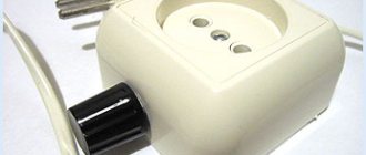
The entire device is assembled directly in the slider body according to the diagram below. A diode is connected to the switch terminals. For a 100 W soldering iron, the diode must have a current of at least 0.5 Amperes. I took the RL207 diode. It is designed for a current of 2 A. This reserve is quite enough for reliable operation. The LEDs are connected in parallel, but in opposite polarity (see diagram!) Thanks to this, their selective operation is achieved. They are brought out of the housing. When the switch is on, the soldering iron receives an alternating voltage of 220 volts and both LEDs light up. When the switch opens, the soldering iron receives a constant voltage , half a sine wave of 220 volts, i.e. 110 volts (either positive or negative half-waves) and one LED lights up. This achieves a decrease in temperature at the soldering iron tip . That is, when soldering you need to choose the heating mode yourself. For example, when tinning pans, full power is needed, but when tinning a small board, half is enough. As a result of even such manual adjustment, the tip practically does not wear out, and the soldering iron itself will last longer. The main thing to remember is that it is not advisable to leave the soldering iron on at full power for a long time.
Source
Modification of the soldering iron itself is not difficult at all
Its essence is simple - remove the triac and connect the soldering iron wire to the heater directly. Personally, I replaced the wire (the wire with the plug will come in handy), and hung the triac by one leg on the soldering iron board. The original regulator is no longer used. I use the twister as a plug and retainer for the board.
I haven't had much practice with this soldering iron yet, but I see no reason for a negative result. The first one I converted works great and is my main one. What should you do if you decide to redo yours? Measure the resistance of the heater when cold and after warming up. Naturally in a state disconnected from the network.
- If they approximately coincide with mine, you can safely repeat them with my denominations.
- If not, then you will have to select the values for R1, R2, R3.
I haven’t experimented with soldering irons with nichrome heaters, so I can’t give any recommendations.
Capacitor and diode for adjusting the temperature of the soldering iron
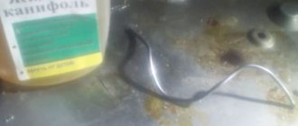
Also, many people solve the problem of overheating of soldering irons by installing a capacitor and diode in parallel. A capacitor is needed for at least 250 Volts, and when connecting it, polarity must be strictly observed. As for installing the diode, a 226 diode is usually used for these purposes.
However, I still would not experiment and would purchase a ready-made device in the form of a dimmer or LATR in order to regulate the output voltage. In any case, it will be much safer than upgrading a soldering iron with diodes and capacitors without knowledge, taking into account all the risks.
Printed circuit board
Now the main thing. Why is all this needed, what does it give? A simple current regulator does not provide stabilization in any way. If there is very little natural cooling so that the soldering iron does not overheat, then when soldering there will clearly not be enough power.
If it’s normal when soldering, then when idle there will be overheating. Inevitably.
This has a very strong impact. For example, my Chinese tips that came with the soldering iron (copper, by the way) simply melted before our eyes. It’s especially unfortunate for the flat one. With a hatchet.
In addition, if it overheats and is left idle for a long time, the tip burns and sometimes it becomes extremely difficult to tin the tip. The solder naturally oxidizes and turns into a gray-black mess. And before soldering you will have to clean the tip every time. In short, the life of the tip and the comfort of soldering are greatly reduced.
A soldering iron modified in this way acquires the features of soldering irons of a completely different price category and quality. This is actually a soldering station.
Another aspect that I checked for myself. Sometimes I solder parts with two soldering irons. Since I now have two such soldering irons, it made sense to check whether there was a potential difference between them that would be detrimental to the part being removed.
Measurements with a voltmeter showed zeros in the range of 20 volts constant and 200 volts alternating. I turned over one of the network plugs. Perhaps it’s just high-quality ceramics in the heaters. True, it’s worth keeping in mind that in the first converted soldering iron, instead of a power supply with zener diodes, there was a Chinese small 12-volt UPS (I didn’t find powerful zener diodes then). Perhaps this is another reason.
Well, why exactly such soldering irons are especially interesting for this alteration.
In normal mode it quickly overheats. This indicates that the heater temperature is too high. And excess power. It has a ceramic heater with a fairly high resistance and a strong change in resistance when heated, which allows you to more accurately monitor the temperature.
Consequently, after the modification it will heat up very quickly, since the voltage is supplied not after the dimmer, in a reduced form, but the full mains voltage.
For the same reason, it will quickly restore the temperature after intensive heat extraction when soldering massive parts.
Temperature stabilizer for a household soldering iron tip
This device, which is easy to repeat, ensures the stability of the temperature of the soldering iron rod set by the regulator (variable resistor) when the mains voltage changes. A miniature incandescent lamp is used as a temperature sensor.
The device we bring to your attention is the result of the author’s desire to obtain high-quality soldered connections with a household electric soldering iron, designed to operate from a 220 V mains voltage with its fluctuations. A temperature sensor is attached to the soldering iron rod, based on signals from which the device maintains the heating temperature of the rod at a given level.
Rice. 1. Stabilizer circuit
The stabilizer diagram is shown in Fig. 1. The stabilizer consists of two units: measuring and regulating, which are galvanically isolated by the network transformer T1 and optocoupler U1. The measuring unit is assembled on op-amp DA2, connected as a comparator, and receives power from the secondary step-down winding of the network transformer. The alternating voltage from it is rectified by the diode bridge VD1, smoothed by capacitor C3 and then stabilized at +12 V by the DA1 microcircuit - a parallel voltage stabilizer.
The voltage at the inverting input of op-amp DA2 is determined by a divider consisting of resistors R7, R8 and incandescent lamp EL1, the current through which is about 3 mA set by resistors R7, R8. As you know, the resistance of the filament changes with temperature changes. This property made it possible to use the lamp as a temperature sensor (hereinafter referred to as the sensor), attaching it to the rod of a soldering iron. The heating temperature of the soldering iron rod is regulated by a variable resistor R6, connected to the circuit of another resistive divider R3R4R5. Both dividers form a measuring bridge. The temperature control limits are set by resistor r4.
When the temperature of the sensor changes, the bridge becomes unbalanced and the voltage at the output of op-amp DA2 changes. The output of the op-amp (pin 6) controls the LED HL1 and the optocoupler U1 of the regulatory unit, assembled on a powerful field-effect transistor VT1. The optocoupler controls the gate-source voltage of the field-effect transistor VT1. When the temperature of the sensor increases, its resistance increases and a low level voltage appears at the output of the op-amp, the LED HL1 goes out, signaling an increase in temperature above the threshold set by the variable resistor R6, and the emitting diode of the optocoupler U1 turns on, opening its phototransistor. The open phototransistor closes the gate and source terminals of the field-effect transistor VT1, its channel closes, and only half the period of the mains voltage is supplied to the soldering iron heater through the diode built into the transistor. The soldering iron rod and sensor begin to cool down. After some time, a decrease in the temperature of the sensor leads to the appearance of a high level voltage at the output of the op-amp; the HL1 LED lights up, now signaling the temperature is below a given threshold, and the emitting diode of the optocoupler turns off. Transistor VT1 opens with a voltage of 12 V at the gate, and the full mains voltage is supplied to the heater. The soldering iron rod begins to heat up. Then the process is repeated. The voltage to the zener diode VD2 to open the field-effect transistor VT1 is supplied from the network through the rectifier diode VD3 and quenching resistor R12. Capacitor C5 is a smoothing capacitor.
Rice. 2. PCB drawing
A drawing of the printed circuit board is shown in Fig. 2. It is made of one-sided foil fiberglass and placed in a housing from a low-power power supply in place of the rectifier board with a smoothing capacitor and a slide switch removed from it. The network transformer of the power supply is used as transformer T1. All resistors are installed perpendicular to the board. A hole is drilled in the housing for the axis of the variable resistor R6, which protrudes outward. The electrical connection of the board with the heater and sensor is made through the ONTs-VG-11-6/16 connector (its contact numbers are shown in Fig. 2). A corresponding hole is made in the housing for the connector. The connector itself is not shown in the diagram. Transistor VT1 is mounted outside the board on a heat sink - a copper plate measuring 90x12x1 mm, curved like a “P” around the transformer. When the soldering iron power is no more than 25 W, a heat sink is not required. Varistor RU1 is mounted directly on the terminals of transistor VT1.
A small-sized incandescent lamp of the DL1250 series (voltage - 12 V, current - 50 mA) with dimensions of 3.2 × 6 mm and a lead length of 25 mm was used as a sensor. When cold, the filament resistance is about 30 ohms. At a temperature of 200...230 oC - about 50 Ohms. Current-carrying heat-resistant wires with a diameter of 0.2...0.25 mm and a length of 250 mm, exposed to high temperatures, are made of constantan wire and laid along the body of the soldering iron. The connection of the wires to the lamp is made by welding, otherwise the temperature of the rod will “float” over time. The wire for the wires can be wound from powerful low-resistance resistors PEV, S5-35. Nichrome wire will also work, but it has twice the resistivity and is more difficult to connect securely. The welded leads are insulated with pieces of fluoroplastic tube from the MGTF wire and wrapped with fluoroplastic tape FUM-O (PTFE) for plumbing work. Next, they attach, wrapping the same tape, a sensor lamp pressed to the heater rod, and current-carrying wires in two or three places along the body. It is advisable to make a small notch on the copper rod of the soldering iron for the lamp. Particular attention should be paid to the reliability of electrical insulation of current-carrying wires and welding points from the housing.
Op-amp LM301A is for general use, we can replace it, for example, with KR140UD7, K153UD2, LM741. The parallel stabilizer TL431 can be replaced with a zener diode KS212ZH, KS212V or its imported analogue. We will replace transistor VT1 with an operating voltage of at least 500 V with MTP6N60, BUZ90 or domestic series KP707, KP726.
Varistor RU1 may not be installed. The W08M diode bridge can be replaced by one assembled from individual low-power diodes, for example, 1N4148, KD521A. Oxide capacitors are imported, C2, C4 are ceramic KM. Resistor R6 - SP4-1. Fixed resistors - any output ones. The DL1250 lamp can be replaced with a DL1265 with a rated current of 65 mA at 12 V (see below).
Rice. 3. Appearance of the stabilizer
The appearance of the assembled stabilizer is shown in Fig. 3.
The stabilizer is adjusted in the following sequence. The motor of the variable resistor R6 is set to the lower position according to the diagram, and instead of the resistor R8, a variable (or tuning) resistor with a resistance of 3 kOhm is temporarily connected to a rheostat. When the stabilizer is connected to the network, the HL1 LED should not light up. Next, reduce the resistance of the temporarily connected variable resistor until the LED turns on. Measure the resistance of the part of the resistor introduced into the circuit and solder a constant resistor of similar resistance instead. After this, if necessary, select the desired heating temperature range with resistor R4. In addition to the lamp filament, especially when replacing it, the resistance of the temperature sensor is also influenced by the connecting wires, so the resistances of resistors R4, R8 may differ slightly from those indicated in the diagram.
The stabilizer has been tested in use with soldering irons with a power of 25, 40 and 90 W. Temperature instability was 15...20 oC. It mainly depends on the quality of the thermal contact between the cylinder of the sensor lamp and the soldering iron rod. The author has been using a stabilizer with a 25 W soldering iron for more than one year. There is practically no need to adjust the temperature.
The presence of the sensor in a glass cylinder mounted on the soldering iron rod requires, of course, some caution during operation to avoid its mechanical damage. A special stand is required.
Author: A. Zvirbulis, Sigulda, Latvia
How to reduce the power of a soldering iron
Wattmeter alipromo.com/redirect/cpa/o/o3kjhux53auqbien7xy7qp799fxrvvsy/ Dimmer alipromo.com/cashback/view/op16je58p0wuk9m0upow5obb02jd5qki/ alipromo.com/cashback/view/opi4nltz3u9yebtwv4747wuwbwl 6rjie/ Dimmer 4000W alipromo.com/cashback/view/opi55mslmetmyj0mhrvcr8p9us5ovgca/
Shamil 5 months ago
I bought myself a dimer for lighting, I adjust the power as much as I need
Stepan Kapusta 6 months ago
It’s an interesting thing, but they don’t make things like that anymore. Now you can use a power button that is attached to a cord and mount a diode of type 1n7004 in parallel with the switch (its body is not as wide as that of D226 or KD202), you can also add an LED for indication by turning it on in parallel to the button through a resistor 82 - 100 kOhm. By the way AliExpress has soldering irons with a button, but they are 200 rubles more expensive, although such a button costs 80 rubles.
steg 8 months ago
Ivan Ivanov 11 months ago
VladimirS38 Rick that
bob komisarjewskij Rick that
author, can you give me a working link to the wattmeter from your video? Or is this model no longer available?
Romanych Rick that
Probably no longer in production. Somehow I searched to update the link, but did not find such a wattmeter. I've only seen similar ones. There are a lot of different wattmeters on the market. There's no point in chasing someone exactly like mine.
Vasya Shtyrkov Rick that
Thank you. It helped to curb a 100-watt Chinese soldering iron, the winding of which was already red-hot and glowing (visible through the gap), and the tin was quickly burning. I inserted the diode into the detachable plug and now the soldering iron works as it should!
Vasya Shtyrkov Rick that
Romanych Dimmer is also a useful thing. But I have to wait a month for it, and I need to solder it now)) I just bought a soldering iron today, and it was overheating.
Romanych Rick that
But it’s still better to use a dimmer, which is sold everywhere. It's not expensive. For reference, link below the video.
Victor Goryachev Like this
This has been used since the 70s, a standby mode is now installed, a voltage regulator, and you can regulate the temperature of the soldering iron.
Volodimir2201 Rick that
Diodes are not divided into models, but are classified by type. A diode connected to the soldering iron's power circuit is a method that has been known for many decades. Often, a powerful resistor of the PEV type - 10 with a nominal value of 1 to 2 kohms was switched on in parallel with the diode, so that the warm-up after the diode is short-circuited was faster. In any case, the soldering iron must be powered through a regulating element, be it an autotransformer, or a thyristor power regulator that has long come into use under the sonorous English brand - a dimer. And the overheating of Chinese soldering irons can be explained by the fact that they are probably designed for a 120-volt supply voltage. And the built-in regulator does not allow you to fully compensate for the increased electrical power of the heater in this case.
How to reduce the power of a soldering iron
If you, a fellow hobbyist, have already “outgrown” a soldering iron with a voltage regulator, but have not yet “grown up” in your ambitions to a professional soldering station, then this might be interesting. The ability to change the supply voltage of a soldering iron designed for 220 V, among other things, allows you to return to operation an already burnt-out one. And use it in the future, for example, with a switching power supply from an imported TV, which at the output gives exactly half of the network one. Bringing these two products together results in an intermediate option between a soldering iron with a regulator and a full-fledged soldering station. Any radio amateur can do this. I’ll show you how to do this using the example of changing the supply voltage of a Chinese-made soldering iron, which was not trustworthy for use without modification.
Compact temperature controller for soldering iron
Personally, I connected my soldering iron without a thermostat to a compact dimmer, which I purchased for only 110 rubles. This regulator has a smooth switch with the ability to adjust the voltage from 110 to 250 Volts. Since then the soldering iron has no longer overheated.
You can also use other devices to adjust the voltage and, accordingly, the temperature of the soldering iron. For example, a dimmer for 220 Volt lamps or a regular LATR.
Disassembling the soldering iron
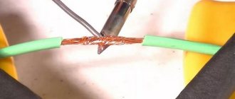
To disassemble the soldering iron, it was necessary to completely unscrew two screws connecting the protective casing to the heating element and holding the tip, and three self-tapping screws securing the working part to the handle. Remove the insulation from the wires and unscrew the connecting twists.
Mica with soldering iron spiral
There is a heating element inside the protective casing. That's what they have to do. It is necessary to change the amount of wound nichrome wire - change the resistance of the heating element. Now it is 1800 Ohms, 400 Ohms are needed. Why exactly so much? Currently working with a UPS, the soldering iron has a resistance of 347 Ohms, its power is from 19 to 28 W, there is a desire to make the second one less powerful, so I added Ohms.
Soldering iron rewind
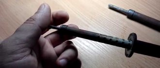
Winding a soldering iron tip
The tip is reinserted into the heater, clamped with screws and into the drill chuck. If you disassemble and unwind excess nichrome while holding the heating element in your hands, then everything will be much more complicated. The tie wire is removed.
The released fiberglass and mica wrappers are removed. In the mica on the side of the tip, there is a slot into which a conductor is inserted, going from the nichrome to the network wire - therefore, the weakened mica wrapper is removed from it rather than unwinding. Mica is a very fragile material. The end of the nichrome wire wound to the conductor is disconnected. Its thickness is just over 4 microns.
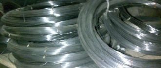
Nichrome must be wound onto something round; the ideal option is a spool of thread. He unscrewed it, rewinded it, and so on until the end. There is no need to disconnect the second end of the nichrome wire.
Soldering iron wire resistance
Now you need to wind a length of 400 Ohms, and in centimeters it will be approximately 70 (the total length of nichrome wire 300 cm is 1800 Ohms, hence 400 Ohms will be 66.66 cm). At a length of 70 cm, a latch (clothespin) is placed and in the hanging position of the coil, slightly guiding with your fingers, winding is carried out at intervals ensuring its termination at the first conductor. The number of attempts is not limited, the main thing is not to tear the nichrome. At the end of winding, a control resistance measurement is required.
As soon as we manage to wind the required amount of nichrome, we cut the wire with an allowance of 1 - 2 cm and wind it to the conductor. We put on the mica winding, passing the conductor into the slot in it and press it against it (naturally on top of it).
We install a fiberglass winding on top and, compacting it by pressing, wind the binding wire. A heating element designed for power supply voltage of 85 – 106 V is assembled.
Soldering iron assembly
Since the working part was previously attached to the handle with incomprehensibly clumsy and short screws, they had to be replaced. To do this, holes for new screws were deepened in the attachment points on the handle.
Before connecting the power cable with the conductors going to the nichrome heater, a plastic clamp was installed and adjusted on it.
The casing of the heating element ends with a kind of cooling radiator, through holes in it and is attached to the handle. To increase the cooling effect, the gap between it and the handle was increased using metal washers.