Instructions for using a PID thermostat for a muffle furnace
The temperature regulator for a muffle furnace is an integral part of heating equipment, since thanks to it it is possible to maintain the temperature inside at the required level.
When working with an electric muffle furnace, it is very important to maintain the accuracy of the settings. The effectiveness of the impact on materials placed inside for heat treatment depends on this. The PID controller for the furnace is used in all types and varieties of equipment in question. Its main tasks are monitoring the current heating state and automatically controlling the process.
How to measure the temperature in a muffle furnace
Very often, ceramists who have a homemade muffle furnace wonder how to measure the temperature in this very furnace. There are several proven methods for this.
1. Determination of temperature by the color of the shard
This is the most cost-effective way. But at the same time it is quite complex, because... The temperature must be determined by the color of the hot ceramics in the furnace. With some skill, this can be done quite accurately. An approximate correspondence between color and oven temperature is shown in the figure below.
2. Pyrometric cones (pyroscopes)
A pyrometric cone is a ceramic pyramid that, under the influence of a certain temperature, begins to soften and fall. Each cone has its own number and is designed for its own temperature range (see picture above).
The pyramids are installed on supports made of a material more refractory than the pyrometers themselves, for example, fireclay, to a depth of 3-4 mm.
Types of temperature controllers for muffle furnaces
A temperature regulator for a muffle furnace is present in any design. Whether it's an industrial furnace or a device in a research center. Since muffle furnaces differ in size, properties and type of activity, different models of thermostats can be installed on them:
Mechanical oven temperature controller
A mechanical oven temperature controller is a well-known device with a printed scale and a moving mark. It does not allow achieving high accuracy of readings and requires the constant presence of maintenance personnel. Therefore, its use is gradually becoming a thing of the past, and more and more furnace models are equipped with modern control devices.
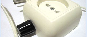
Sample mechanical thermostat
Automatic Muffle Furnace Controller
The automatic controller of the muffle furnace is controlled using a microprocessor. This approach provides many advantages:
- Possibility of setting the required temperature values.
- Carrying out high-precision heat treatment.
- Simplicity of settings and ease of use.
- There is no need to find a dispatcher-operator.
Digital single task thermostat
PID controller-programmer for muffle furnace
The most popular today is a PID controller-programmer for a muffle furnace. This abbreviation stands for “proportional-integral-derivative” controller.
Its work is based on monitoring the state of a functioning unit and generating the corresponding signal. The analysis is carried out in three stages:
- Proportional . Indicates an immediate response to the current process with the elimination of possible inaccuracies.
- Integral . The deviations that occurred during the entire period of operation are assessed.
- Differential . A forecast is made for the future and to prevent the repetition of mistakes.
Many programmers have two digital displays, which display not only the set temperature, but also the current temperature. It is measured by special sensors that transmit information about both heating and cooling
PID controller for muffle furnace
Types of muffle furnace control or which control unit is better to choose
The muffle furnace used in laboratories, workshops, workshops or production is controlled using special regulators. Thanks to control devices, it is possible to carry out various types of heat treatment with extreme precision - heating, drying, cupelling, cremation, ashing, firing or melting of various materials, etc. The technique is used in jewelry and pottery, dentistry, metallurgy, etc. You can buy a muffle furnace to work with ceramics, metal alloys and other samples.
Temperature regulators used in muffle furnaces can be built-in or remote
Types of control units for muffle furnaces
The choice of control unit for a muffle furnace depends entirely on the intended operational tasks. In some cases, setting the exact temperature is sufficient, in others a complex cycle of programs is required. To understand what type of equipment is best suited, first of all, study the features of muffle furnaces for ceramics, glass, metal and other materials. The simpler the loads and number of operations, the fewer options you will need.
Multifunctional control units make it possible to minimize operator participation in work processes, since the entire cycle will be automated
Thermostats for controlling a muffle furnace can be divided into two main groups:
Analog
A regulator with a mechanical operating principle is becoming increasingly rare. It is a rotary handle with a risk on it. It is enough to install it opposite the required temperature mark.
The disadvantage of the analog control unit is a large percentage of inaccuracies. Setting and maintaining the temperature is influenced by a large number of subjective conditions
Digital
Such muffle furnace control units are relevant in various fields; they are reliable and practical. Depending on their capabilities, digital controllers are divided into:
- Simplified . The monitor can display both the set and current temperature. Some models have a timer. In such devices it is not possible to set operating cycles.
- Electronic . Most often, the device is equipped with two screens, where both the necessary and actual characteristics are immediately demonstrated. Multifunctional models allow you to set not only the heating speed, but also the holding time.
- With programmer . Thanks to the built-in microprocessor and timer, it is possible to set up to thirty program steps.
A one-time display of set and current temperature indicators is displayed using numbers and other symbols
Functions performed by the muffle furnace control unit
The digital control unit of the muffle furnace with a microprocessor controller is not only simple, but also easy to use. With it you can:
- Perform high-precision heat treatment.
- Set the required temperature with minimal errors.
- Install a full operating cycle of heating equipment.
To make the muffle electric furnace 3 1100 or another model easy to use, it is enough to install a thermostat. You can select it taking into account the characteristics of the equipment used.
Modern control units for muffle furnaces are equipped with a convenient push-button keyboard and high-contrast LED indication
Programmable control of the muffle furnace allows you to set the holding, heating or cooling period. If a connection to a computer is provided, the operation of the unit can be monitored remotely.
How to assemble a control unit for a muffle furnace with your own hands
When making a muffle furnace with your own hands, you can not bother and buy a ready-made electric furnace control unit, using what is written above to select a model. But many craftsmen, confident in their abilities, prefer to assemble this device themselves. And this is what the second part of our article is about. We will tell you how and from what parts you can assemble the “brain” of your stove yourself.
The use of electronic programmers allows you to maintain the operation of the electric furnace in automatic mode, with minimal human intervention
What elements does the muffle furnace control unit consist of?
Let us list what devices you need to use to independently assemble the muffle furnace control unit. The electrical part includes the following components:
Thermostat
As already mentioned, the thermostat for a muffle furnace is selected depending on the area of activity. There are two main types:
- Mechanical . This type of device is familiar to everyone - a dial with divisions and a handle. The desired temperature is set by turning it to the desired mark. This device is quite primitive and does not allow achieving accurate indicators.
- Digital . The simplest is an electronic device with a screen that displays the set and current temperature. It can be additionally equipped with a timer. Devices that allow you to control the heating rate and operating time have become widespread. After completion of the operation, the regulator automatically turns off. Models with a built-in programmer are used to perform multi-stage tasks.
Thermocouple
A muffle furnace thermocouple is designed to measure the temperature inside the chamber. Data from it is sent to the thermostat, which controls the work process. This sensor is located on the back wall of the camera in a pre-prepared hole. For electric furnaces, thermocouples with the names “HK”, “XA” and “PP” are used. They are connected through special connectors or using electrical terminals secured to the housing with screws and nuts.
Tips for installing a thermostat for a muffle furnace
The temperature regulator for a muffle furnace, the instructions for which are simple even for beginners, comes complete with the main equipment. If desired or if necessary, it can always be replaced. This work is not difficult, the whole process takes very little time.
In addition to the instruction manual, on the side of the device you can find a detailed diagram for connecting the terminals, marked by number. The polarity is indicated next to each designation, which must be observed.
Location of the programmer connection diagram
During operation of the device, the current heating temperature of the furnace is highlighted in red, and the specified parameters are highlighted in green. If a difference occurs in the data, the relay is activated, to which the controller signal is supplied.
If the connection is made incorrectly or the user has mixed up the wires, the system will inform about this by displaying negative values
Laboratory furnaces and industrial units cannot do without thermostats. Any production or research activity implies mandatory compliance with the accuracy of the settings. The required controller for a muffle furnace can be purchased at specialized retail outlets or online stores. Contact trusted suppliers, such as the Labor trading house, whose employees will always help you choose the right equipment.
Source
Add a link to a discussion of the article on the forum
RadioKot >Schemes >Analog circuits >Household appliances >
| Article tags: | ThermostatAdd tag |
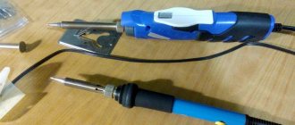
Two thermostats.
Author: Sir Murr Published 10/16/2006
We present to your attention diagrams of two thermostats: the first is for liquid media for a temperature range from 00 C to +125 0 C (although it is not prohibited for air media),
the second is for powerful electric heaters, for example, a muffle furnace for a temperature range of +200C...+10000C.
The diagrams are divided into functional units (or blocks). Both thermostats have the same components: Digital temperature indicator, which is used to take readings and set the desired temperature (the diagram is on our website); Unit for comparing the measured temperature with the set one; Heater proportional control unit; Heater activation unit; Power supplies and reference voltage settings. The digital indicator circuit is described in detail in the article “Digital Indicator”, and the temperature measurement unit for a liquid thermostat is discussed in the article “Converting a digital indicator into a digital thermometer”. Both articles are located on our website.
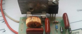
Let us now consider the operation of the proportional heater control unit. Most simple temperature control circuits implement the so-called “relay” method of controlling the heater - while the temperature is below the set one, the heater is turned on, when above the set one, it is turned off. This method has a drawback - the heater makes all the noise, even when the temperature is close to the set one. As a result, after the heater is turned off, the temperature inertia jumps beyond the set limit, then drops to the switch-on temperature, then jumps beyond the limits again - that is, it is not maintained at the set level, but fluctuates up and down around it. It’s good if this process is fading. But still, the temperature exceeding the specified limit is not desirable. To combat this phenomenon, a proportional control unit was used. As long as the temperature is below the unit's response threshold, the heater is constantly on. As it approaches the set temperature, the unit begins to turn off the heater for certain periods of time, which are longer, the closer the measured temperature is to the set one. Thus, when adjusting the switching threshold of the unit, an accuracy of maintaining the temperature of 0.1 0C was achieved on the liquid thermostat. On the thermostat for the muffle, the situation is worse; there, due to the very large temperature inertia of the chamber, a temperature “run-out” of up to 10 0C is observed, but at temperatures of several hundred degrees this is not significant. I agree with the objections that such a unit can be implemented using a linearly varying voltage generator and a comparator, but the proposed circuit is simple and quite repeatable. The output of the node is loaded onto an optocoupler thyristor type MOS3061, which, in turn, turns on a powerful thyristor that controls the heater. The MOS3061 thyristor optocoupler is notable for the fact that it turns on when the switching voltage passes through zero, and therefore switching noise is practically eliminated. ( Earlier, Sir Murr built a whole circuit to implement this principle of operation - on three transistors and a low-power thyristor - note from Sir Murr's cat
). And one more feature of the proposed unit is that power control is carried out by an integer number of periods of the mains voltage, and not by a cutoff angle, which also helps to reduce interference. Well, the power supply does not need a description. The reference voltage is 1,000 volts - the equivalent of a temperature of +10000C for a muffle or +100.00C for a liquid. You can select other values.
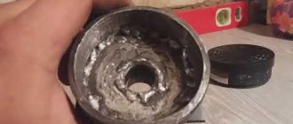
Now about the temperature measurement unit for the muffle. Temperature measurement - thermocouple. To compensate for the temperature of the cold junction (experts know what it is), two identical thermocouples are used - one, the top one in the diagram, is a measuring one and is located inside the furnace; the second, the bottom one in the diagram, is located at the input terminals. The thermocouples were made independently by welding two pieces of TXA type thermocouple wires 2 meters long in a gas burner flame - both ends were welded. Then one thermocouple several centimeters long is cut off - this will be a compensation thermocouple. And everything else is a measuring thermocouple. AHTUNG! Do not forget about the polarity of the thermocouples in the diagram - they are connected oppositely! A resistor is installed at the output of the thermocouple signal amplifier, which calibrates the measured temperature. On the one hand, if the temperature characteristics of the thermocouple are known, then the thermo-EMF can be immediately converted into temperature. But what if the characteristic is unknown? Or is the thermocouple made of something unknown? ( You can use a wire from an incandescent light bulb on which the filament is held as one of the wires, and steel or nichrome as the other wire - try it! - note from Sir Murr the cat
). This is where the trim resistor comes in handy.
I’ll tell you right away about the calibration process. We set the P1 trimmer to the upper position, lower the measuring thermocouple into a mixture of water and ice, and set the P5 trimmer to 0 degrees on the indicator. Then we melt a lot of lead on a gas burner (the more the better) and place a measuring thermocouple there, after first removing... removing it! ( Be smart! Check out the website “GRAMOTA.RU” - note from the cat Sir Murr
) thermocouple from a cold bath and drying it.
We begin to monitor the cooling process of pre-molten lead using a digital indicator. During the cooling process, the melt crystallization point will be passed. At this point the temperature will remain constant, and we will have time to record it. Now it’s clear why the more lead, the better? That's right, to more clearly fix our control point - +327.50C. But! This is the melting and crystallization temperature of pure lead, without impurities! The crystallization temperature of lead alloy will be different! ( The melting or crystallization temperature of tin is +2320 C, zinc + 419.60 C - note from the cat Sir Murr
) We record the crystallization process by the constancy of the meter readings, and visually by the cessation of the shine of the liquid metal. And now we use the P5 trimmer to set the treasured point 327 on the thermometer.
And now a little about the pitfalls of this calibration and measurement method. Our meter has a linear scale over the entire measurement range. In fact, the characteristic of any thermocouple differs from linear, although it is quite close to it. Moreover, the more sensitive the thermocouple, the more nonlinear it is. Industrial microcontroller meters take this nonlinearity into account and make appropriate corrections. And you and I ignore this unknown nonlinearity. Screw her - we already have enough precision! And now our thermometer can be checked by the boiling temperature of water +100 C, if you live at an altitude of no more than 500 meters above sea level. Otherwise, you will have to make an adjustment for the decrease in boiling point as atmospheric pressure decreases. Or vice versa - for a promotion, if you are a gnome in your own underground factory.
Now some recommendations about the design. It is better to make inputs and outputs of power circuits on screw terminal connectors; connectors from computer network cables cannot withstand a current of more than 10 amperes. For example, they melted in a muffle furnace. True, the muffle is 3 kilowatt...
For a liquid thermostat, it is necessary to organize water circulation - in any way - with a pump, an aeration compressor from the aquarium, or stirring with a spoon. Otherwise, the temperature at the bottom and on the surface may differ by several degrees. And we claim an accuracy of 0.1 degrees.. To force the cooling of the liquid thermostat to turn on, a comparator on the MS A4 is used. Of course, this node is not required, but it can be useful if you need to record the cooling process from a given temperature. Setting the required temperature is carried out by pressing the button, which is initially fixed to measure temperature. And when you press the button, please set the temperature by screwing up the setting resistor (preferably multi-turn). Well, that seems to be it. The author is grateful to his cat for his valuable comments while writing the article.
As usual, we put the questions here.
| What do you think of this article? | Did this device work for you? | |
| 13 | 4 | 0 |
| 0 | 0 |
These articles may also be useful to you:
Radiator thermostat-thermometer-voltmeter-car
Thermostat for heated floors.
Thermal controller "Murka"
Automation of temperature conditions in the process of ethyl alcohol production.
K-type thermocouple thermostat
Budget thermostat for a gas boiler.
Two-zone thermal control, “ThermoOpa”. For soft electric heaters.
Thermostat on a PIC16F84 microcontroller and DS18B20 sensor.
A very simple thermostat for heating.
GSM thermostat + GSM alarm
Oven thermostat: what is this device, its functions and operating principle
Quite a lot of household appliances have been invented; they serve different purposes, but there are several types of units that no house or apartment can do without. These are irreplaceable kitchen assistants - those that store food and those that help prepare it. If life becomes very difficult without refrigerators or freezers, then it is simply impossible to do without stoves. But, like any other equipment, at one “unfortunate” moment they fail, so the owners have to either fix the problem or choose and purchase a new model. It is the last operation that sometimes causes great difficulties, primarily because of the oven, on which the comfort of cooking largely depends. The thermostat plays a minor role in the operation of this part of the device. Therefore, many future owners of “cook” appliances are trying to figure out what an oven thermostat is and how important this unit is.
The simplest muffle furnace for ceramics
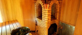
To make such a simple device, you only need an ordinary electric stove, a clay pot and a piece of fireclay brick.
- Place a piece of brick on the stove so that the fired ceramic does not touch the spiral on the tile and cover it with a pot. You regulate the power with a thermostat.
- Now you watch the pot - as soon as a red light begins to shine through its walls, you mark the time for firing. As a rule, this is 10-12 hours.
Pot muffle furnace
A few words about gas ovens
Since the main character of the article is the oven thermostat, and gas appliances remain the most common due to the cheapness of fuel, we need to talk a little about them. The reason for this retreat is the “indecently” wide range of these units.
Types of ovens, structure and principle of operation
There are appliances that are installed separately, and ovens that are combined with the hob. Burners located inside the structure are responsible for cooking food in the oven. There are three types of heating. You can find different models on sale:
- Units with a grill - with burners located in the upper part of the cabinet.
- Standard gas stoves with normal heating. This is a classic option - burners that are located at the bottom of the cabinet.
- Convection appliances. In this case, the heating elements are also located at the bottom, but even heat distribution is ensured by the fans built into the device.
Fusing furnace control unit
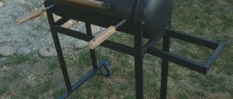
The control unit is designed to control a homemade furnace for fusing (decorative sintering of colored glass) and is designed as part of the furnace - on its side wall. This made it possible to insert all the leads (heaters and thermocouples) into the control unit through the wall, while the leads were as short as possible; there were no adapter interconnect cables, wires, connectors or terminals. Highly effective thermal insulation and air gap prevent the control unit from overheating during operation.
Furnace heaters – 12 pcs., combined into three groups (3 phases) of 4 2 kW heaters connected in series. It turned out 3 groups of 500 W, the total power of the furnace, respectively, is 1.5 kW. To switch the heaters, homemade electronic switches based on triacs, analogues of solid-state relays, are used. Structurally, each key module is assembled on an aluminum base (used as a heat sink) from an old PC hard drive.
All intermediate connections of the wire heaters are inside the working chamber (welded), only the group terminals go outside; homemade transformer current sensors with indicators on the front panel of the unit allow you to monitor the integrity of all these connections and the heaters themselves.
The sintering process is quite complex and contains 7…8 steps. Each stage involves holding the workpiece at a certain temperature for a specified time; in addition, the rate of temperature change between stages is extremely important. Small workpieces allow for a simplified sintering schedule, and changes between multiple stages can be made manually using a timer. The equipment for such work can also be quite simple. In this case (small linear dimensions), the resulting internal stresses do not reach destructive values. As the dimensions of the workpiece increase, the requirements for changes and maintenance (selected experimentally) of time and temperature also increase. The process can last 12…16 hours. Manual control of such a process is difficult; a programmable thermal controller is required. Here, a programmable thermal controller from a soldering station for microcircuits in BGA (leads-contact pads on the bottom of the microcircuit) packages is used. The design of the case does not allow mounting such a microcircuit with a soldering iron; it is heated through. the thermal profile are also obvious.
and the ability to regulate the rate of rise and fall of temperatures. This makes both tasks similar; practice has also shown the complete suitability of such a controller for glass sintering. A Chinese-made controller works great and is much cheaper than specialized devices.
What was used for the job?
A set of tools for small plumbing work, a set of tools for electrical installation. Materials - in addition to radioelements, you needed sheet steel for the body of the device, a piece of plexiglass for the front panel, fasteners, small items, paintwork materials.
To the point.
All electrical terminals are located on one of the sides (right, under the working hand) of the upper part of the furnace (hinged lid) - 6 terminals from 3 groups of heaters (3 phases), thermocouple terminals. In advance, before installing the refractory lining of the furnace, a number of M5 screws were welded into the frame on this side for fastening the control unit.
First of all, I cut out the base plate for mounting the elements of the control unit (hereinafter referred to as the control unit). Sheet steel 1.5 mm, grinder. I drilled and used a magic file to adjust the holes so that the board fits exactly on the protruding fastener, and the ceramic insulators easily pass through the corresponding holes.
The control unit left an air gap between the metal base plate and the furnace frame for ventilation. 12…15 mm. To do this, I screwed several nuts and washers onto each screw under the board.
I selected a convenient location for three electronic key modules, drilled holes for their fastening, and cut out parts for the front and rear walls of the control unit. On the front wall of the block I cut out openings for installing control and display elements. In the places where the wiring harnesses are supposed to be laid, I drilled holes for their fastening.
The installation of the front and rear walls with triangle struts was done by soldering. I used regular POS-60 and acid stained glass flux, but “soldering acid” (zinc chloride) and phosphoric acid also work well on steel. The pieces of iron are massive; in addition to a powerful soldering iron, it is better to use additional heating. A laboratory electric hotplate is used here. Together with a 150 W soldering iron, they coped with the task perfectly. Heating with a gas torch or a hair dryer is less convenient and can lead to warping of thin metal. After soldering, without delay, you should wash off the remaining flux. Warm water with a brush, or better yet, a weak soda solution.
Indication of the integrity of heaters (current transformers) is collected on miniature neon bulbs. I regarded this information as reference, auxiliary, and in order not to liken the control unit to a Christmas tree, I made the indicators not too bright, small in diameter and near the edge of the front panel. I adjusted the brightness using current-limiting resistors and achieved “precision” by releasing only small glass balls out of the block at the end, the end of the bulb cylinder. It turned out amazingly well, the display is clearly visible, but it doesn’t hurt the eyes. To install the light bulb, I soldered it into a simple printed circuit board; it is attached to the panel with two pieces of thick copper wire. Soldering. On the outside, the indicators are covered with a layer of plexiglass.
A three-phase 10 A “automatic circuit breaker” is installed on a piece of DIN rail soldered to the base. Along the edge of the “brace” square, I drilled holes for attaching wires and harnesses.
The prepared base with the front and back panels was cleaned, degreased and painted. I worked with sandpaper, wiped it with a cloth soaked in gasoline, and painted it with rust-resistant enamel primer in two layers.
After the base had completely dried, I installed (soldered in) a strip with neon bulbs and screwed in triac switch modules. I cut out a transparent cover for the front panel from a plexiglass plate, drew and printed explanatory notes for it. The transparent panel does not have its own fastening and is held in place by fastening the installation elements - buttons and thermal controller.
The assembled panel was installed on the stove. Nuts-washers, lock washers. The protruding parts of the screws were cut off with a thin abrasive disc of an angle grinder.
Electrical installation.
The wire leads of the heater groups are connected to a thin copper wire through a metal piece - an element of a powerful screw terminal. The furnace is controlled by a programmable controller Altec-410 (item 1); To interface with triac switches, an intermediate module (item 2) is used, the rigid wire leads of which are clamped in the screw terminals of the controller. The control signal is supplied to three triac modules (item 3); the integrity of the circuits (heaters) is controlled by current transformers (item 4) with indicators on the front panel (item 5). To start and stop the program, external buttons (pos. 6) are connected to the controller; the “start” button must be kept closed during operation
.
Three-phase voltage is supplied through circuit breakers (pos. 7). The power cable is five-wire (“zero”, 3 phases, grounding) and is made up of two soft wires in double insulation (2 and 3 wires) of the appropriate cross-section. The stove is separate, the power socket is located on the ceiling.
After testing the CU in operation, a U-shaped casing was made from 0.45 mm galvanized steel by bending. Its upper front side is somewhat elongated and forms a small visor above the front panel of the block. This reduces the accumulation of dust and debris on protruding parts and reduces side illumination. For air circulation inside the block, the fields of holes are marked and drilled on the upper and lower walls of the casing in accordance with the location of the key radiators. The casing is secured with four self-tapping screws.
Babay Mazay, April 2021
Become the author of the site, publish your own articles, descriptions of homemade products and pay for the text. Read more here.
Oven thermostat: what is this device?
It is not difficult to understand that if the first part of a compound word is the prefix “thermo-,” then we are talking about high temperature. But this knowledge still does not provide an understanding of what this device is intended for. This unit is responsible for controlling the temperature in the oven. The thermostat, or thermostat, automatically adjusts this setting, turning the heating on or off, increasing or decreasing the temperature.
As a rule, a thermostat is called a thermostat, and vice versa. In fact, these are different devices that have both similarities and differences.
- General. If the thermostat is capable of independently maintaining the temperature at the required level, then it can rightfully be called a thermostat. When it is part of this device, this name will also be correct.
- Difference. The thermostat can be a separate, independent element. The thermostat is a self-functioning structure that also includes a thermostat. The task of the first device is to change the temperature, the function of the thermostat is to maintain the temperature.
These devices are available in both gas and electric ovens, but the principle of their operation in old and new models, in devices of different types and manufacturers, may differ slightly. The oven thermostat is located just behind the oven panel control knob. When it is turned, the owners change the temperature regime, and its adjustment is ensured by the oven thermostat.
Such devices are used not only in this type of household appliances. Thermostats are elements of all systems where something needs to be heated or, conversely, cooled. Examples include heating appliances, automobile engine cooling systems, industrial ovens, climate control systems, refrigerators, etc.
Thermostat operating principle
The handle itself is considered part of the thermostat - the thermostat, or the stove control valve. If we look at older models of gas stoves, the device looks relatively simple.
A thin (capillary) copper tube is connected to the thermostat capsule; at its other end there is an assembly probe, which is installed directly in the oven. The mini-cup and tube contain liquid (eg glycol). When the probe heats up to the required temperature, the liquid expands and acts on the control unit, turning off the device. When the oven begins to cool, the thermostat quickly increases the fuel supply, allowing the oven to warm up.
Types of thermostats
Thermostats can be mechanical, electromechanical or electronic.
Mechanical devices
The first designs are most often used in ovens of gas units. They do not contain electronic components. Such nodes work quite simply.
- After the gas supply valve opens, the maximum amount of fuel begins to flow into the oven until the temperature reaches the set value.
- When the temperature is reached, the thermostat limits the operation of the tap, turning it to minimum mode. The temperature stops rising and remains at the same level for some time.
- After a slight drop in temperature, the device again begins to supply fuel to the maximum. When the indicator reaches the desired value again, it switches to the minimum mode again.
Despite the simplicity of this unit, after it fails, this device must be replaced entirely. The main elements of a mechanical regulator are a gas-filled flask, a capillary tube and a membrane. It is not recommended to disassemble and reassemble this structure, which operates with potentially hazardous fuel.
Electromechanical units
Such thermostats contain contact groups, or pairs. This type of device is divided into 2 groups.
- The first contains devices that include a capillary tube, a membrane, and a gas-filled flask. The last element acts as a temperature sensor. This flask contains gas, which is enclosed between metal disks. When the temperature rises to a predetermined value, the substance expands, separating the disks. Those, in turn, open the circuit. After the gas cools, the disks converge again, closing the contacts.
- In the second group, the temperature sensor is replaced by a bimetallic plate. The operating principle of this device is based on unequal heating of elements made of different metals. One plate heats up less and therefore does not change. The second one bends as the temperature rises. As long as both plates remain level, the electrical circuit remains closed. When deformation of one metal element occurs, it opens.
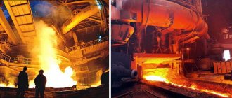
An unusual muffle furnace will process any material
- High temperature muffle furnaces
- Varieties: gas, electric, with temperatures of 1100, 1300, 1700 degrees
- How to operate the oven? What is a thermocouple used for?
- Scope of application: from chemist to jeweler.
Fume hoods - Examples of models: 220 and 380 volts; 2, 3, 4 kW; 50, 400 liters
- Temperature regulators, controllers for muffle furnaces: analogue, digital, programmers
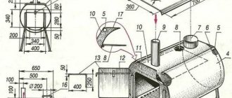
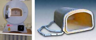
The product that needs to be heat treated is placed in a muffle made of a special fire-resistant material, for example, ceramics or corundum . Such materials have extremely high thermal conductivity and good density.
Photo 1. Diagram of an electric muffle furnace: both external and internal sides are shown.
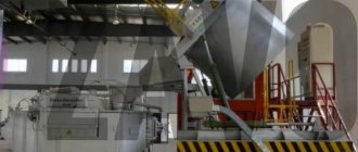
The air inside the muffle is heated to a certain temperature, which is maintained at the same level until the end of firing . Heating elements in the form of wire are responsible for supplying thermal energy. Next comes a layer of thermal insulation material, mainly from ball screws/shvpkh.
Some manufacturers supply their devices with powerful ventilation systems . A separate exhaust mechanism is responsible for removing steam and smoke.
The entire structure is sheathed with a reliable metal casing approximately 1.5-2 mm . To achieve high temperatures ( over 1150 °C ), manufacturers began to produce muffles from a special fibrous material. Its significant disadvantage is its fragility.
Under the influence of gas fumes and other chemicals, the fiber structure soon loses its shape. There are also fireclay muffles with heaters hidden in the grooves of the lining.
Reference. The volume of the internal chamber can vary from one to two hundred liters . Large structures take longer to heat up than miniature models. More electricity is spent on massive furnaces, since part of it is spent directly on heating the muffle.
Varieties: gas, electric, with temperatures of 1100, 1300, 1700 degrees
By purpose:
- Muffle furnaces . Designed for processing specific materials at high temperatures.
- Drying cabinets . The maximum temperatures are lower than in muffle ones. Used for drying, heating, calcining and testing various materials in air.
By type of energy source:
- Gas. Allows significant savings in fuel consumption.
- Electrical. Most often used in large enterprises. Tapes, wires, rods, profiles and tubes for such furnaces can be made of platinum alloys, tungsten, molybdenum, tantalum, nichrome and fechral alloys, lanthanum chromite, yttrium chromite, scandium chromite. Their power supply is 220 or 380 volts , depending on the size of the chamber.
By heating temperature in degrees Celsius:
- Moderate temperature - from 100 °C to 1100 °C.
- Average temperature - from 100 °C to 1300 °C.
- High temperature - from 100 °C to 1700 °C.
By design:
- Horizontal loading/simple - loaded from the side. They have virtually no competitors in terms of the number of fireboxes heated simultaneously in the oven.
- Top-loading/pot - loaded from the top, not separated from the hearth. Provide more efficient work with shock investment masses and faster release of combustion products.
- Bell-type - loaded from above, separated from the hearth after heating.
By processing mode:
- Air , where the muffle limits the movement of air masses between the heaters and the working space.
- With a gas atmosphere, where the gas can be nitriding, inert, reducing, and so on. The most commonly used gases are hydrogen, nitrogen, argon and helium.
- Vacuum , where a rarefied space is artificially created in the inner part of the muffle.
There are different powers: 1.5 - 3 kW; 6, 18, 26 kW.
There are also different oven sizes: 200 x 300 x 200; 300 x 300 x 300; 400 x 300 x 400 and others.
Laboratory muffle furnaces deserve special mention . They are characterized by high technical equipment, the ability to instantly replace the muffle and almost ideal accuracy of operating parameters. Such designs are used to conduct experiments in order to find out ways to improve a particular product.
Laboratory muffle furnaces heat up extremely quickly to the required temperature. As a rule, they are equipped with timers. Their chambers need to be changed frequently, since each raw material requires special heating conditions. The bottom of such a device should be equipped with silicon carbide plates and an additional tray to protect the heating elements.
Attention! Operation of muffle furnaces is possible at temperatures from +5 °C to +40 °C . The permissible humidity level in the room should not exceed 85% .
How can you check the oven thermostat?
Any device is not immune from malfunctions. Thermostats are characterized by two types of problems: error - discrepancy between real temperature indicators and those set, and constantly closed or open contacts that no longer depend on temperature.
Mechanical model
If your home appliance has a mechanical thermostat, then identifying the problem is easier. In this case, first turn on the oven, setting the lowest temperature value. The switched on device is left to heat up for 15-20 minutes. After this time, the flame should become minimal: it remains stable.
To check the thermostat of a gas oven, after a specific temperature has been set, it is recommended to observe the burner flame for a while. If it remains at the same level or decreases, then we can conclude that the equipment is working normally. The second method is to use an additional thermometer; an alternative (or assistant) is a multimeter with a thermocouple.
Electromechanical device
Such a thermostat makes it possible to check its performance in two ways.
- Traditional method. The oven is turned on, then the regulator is set to 100 or 150°. The temperature in the chamber is checked with a thermometer after some time. If the device is working properly, the real and set value should match. An error in the readings directly when turning the device on and off is not a malfunction, it is a feature of its operation. For example, when setting 150°, the oven thermostat will turn off the heating when it reaches 155°, and when it drops to 145°, it will turn on the heating. As a rule, a difference of 5° is considered normal.
- The hard way. In this case, the device is disconnected from the device, contacts are found, which are removed and connected to each other. Then a tester is connected to them, which is set in advance to the ringing mode. If the oven is cold, then they must ring briefly, since the resistance is almost zero. Then the thermostat is moved to 150°. If after 10 minutes the tester does not show a gap, then the knob begins to be slowly turned in the direction of decrease.
The second method is considered less accurate, but it is quite suitable for diagnosing the thermostat of a household appliance. In any case, differences in readings of 5-10° are acceptable. Large errors are already evidence that the thermostat needs to be replaced (mechanical or electromechanical) or repaired (electronic). However, sometimes the problem is not the thermostatic unit, but the door, which may not fit tightly. It is better to invite a specialist to repair it.
Electronic device
In this case, the first method of checking the electromechanical unit is optimal. If a complete diagnosis of all structural elements is necessary, then the operation of the relay is tested, the resistance of the sensor is measured, and the functionality of the controller and the integrity of the conductors are checked.
Making a muffle furnace with your own hands
In the production of various ceramic or metal products requiring heat treatment, a muffle furnace is used. When processing products, a factory-made model or a home-made muffle furnace can be used in compliance with all safety requirements and regulations. A do-it-yourself muffle furnace must be equipped with heaters of sufficient power to perform various operations related to the heat treatment of products.
Production and use
Muffle furnaces are widely used in the production of various products at industrial enterprises, educational institutions, repair enterprises and jewelry workshops.
To carry out laboratory research, a Snol muffle furnace is used, which hardens, roasts and heats various materials. Material processing performed with Cnol allows for the melting of metals, the production of dental prostheses, and the hardening of ceramics.
Cnol equipment is manufactured by JSC Napal located in Solnechnogorsk, Moscow region. The list of equipment includes models with a working chamber volume from 3 to 40 liters and includes models:
- PM Cnol 10/10;
- PM Cnol 10/11;
- PM Cnol 6/10;
- PM Cnol 3/10;
- PM Cnol 30/13;
- PM Cnol 40/118;
- PM Cnol 7.2/13.
with a chamber operating temperature from 1050 to 1300 °C (depending on the model). To regulate the temperature regime, a special thermostat is used that allows you to change the temperature in the chamber. To perform technological operations associated with large formation of combustion products, a special fume hood is produced, in which a Cnol muffle furnace is placed.
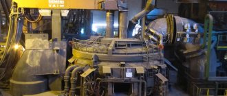
Industrial enterprises produce various muffle furnaces EKPS 50 3U, MIMP-10P, MP-2UM, EMP 12.1 M "Averon".
Electric muffle furnace EKPS 50 ZU
Naberthem (Germany) muffle furnaces are used in the production of ceramic products, used in more than 100 countries. In the list of equipment produced, a special place is occupied by models for firing ceramics with a working chamber volume from 16 to 2200 liters and a heating temperature of up to 1340 °C:
- Top 16/R+B400 Naberthem;
- Top 45+B400 Naberthem;
- Top60L+B400 Naberthem;
- Top 80+B400 Naberthem;
- Top 130+B400 Naberthem;
- Top 160+B400 Naberthem;
- Top 190+B400 Naberthem;
- Top 220+B400 Naberthem.
Naberthem offers a wide range of laboratory equipment:
- laboratory smelting;
- soldering;
- chamber (with fibrous or ceramic insulation);
- agglomeration;
- muffle;
- for ashing;
- for firing ceramics.
Types of muffle furnaces
Furnace models are divided according to 2 main characteristics:
- the energy source used;
- body designs.
Muffle furnaces use 2 main energy sources:
When making a muffle furnace with your own hands, it is most advisable to use heating elements as a heating element, since when using gas, the requirements and standards for the device create significant difficulties during assembly.
Structurally, furnaces are divided into:
- tubular;
- vertical;
- bell-shaped;
- horizontal.
Heating or firing of products can be carried out in various environments, according to the technology used:
- in a gas environment;
- in a vacuum;
- in the air.
The most affordable and simple option for making a muffle furnace is heating products in air, which does not require additional equipment or financial costs.
What to do if the thermostat misinforms?
If the device does not work correctly, then there are two possible solutions to the problem - replacing the thermostat or calibration.
How to replace an oven thermostat?
This is the simplest unit, so you can replace it yourself, especially if the owner-master already has skills in such work. First, purchase a device similar to the one installed in the oven. The replacement operation itself consists of several stages.
- First, remove the control valve from the oven panel, then loosen the screws securing the thermostat.
- Before proceeding with further actions, the wiring diagram is recorded on paper or photographed.
- Then carefully disconnect the probe of the device, remove the old thermostat, replace it with a new design, and tighten the loose screws.
The purchased unit is connected according to the printed diagram, the probe is connected, then the regulator knob is returned to its place. After completing the work, check the new element with a conventional, mechanical thermometer. If the readings coincide or diverge minimally, we can assume that the work has been completed successfully. This procedure is carried out when replacing mechanical or electromechanical devices.
Simple device adjustment
This fix option is simpler, and there is no need to purchase a new unit. But this method is only suitable for older models. In this case, proceed as follows:
- In the same way, remove the control knob from the oven control panel. Two screws are found behind it; they are loosened, but not removed.
- A screwdriver is inserted into the groove, then a simple “calibration” is performed - the adjusting screw is turned. If it is necessary to lower the temperature, then move it counterclockwise; to increase it, turn it clockwise.
Some thermostat models provide the ability to adjust using a screw located on the shaft housing. One eighth of a turn of the screwdriver increases or decreases the temperature by 25°.
Not all owners immediately look for a repairman in the event of any malfunction, since in some cases you can easily find information and then restore the operation of the devices yourself. For example, the following video will tell you how the oven thermostat works and what to do if it goes on strike:
Source