Technology of electric spark processing of metal
Industrial processing of metals includes several dozen methods and techniques for changing the shape, volume and even the molecular structure of a material. Electrospark processing of metals is one of the most common technologies for working with metals, characterized by high accuracy and productivity. Using electric spark machines you can:
- cut metal;
- drill holes of microscopic diameter;
- increase defective areas of parts;
- produce jewelry work with precious metals;
- strengthen the surface of products;
- grind products of the most complex shapes;
- remove stuck broken drills and cutters.
Many industrial machines have been created based on the electric spark method of metal processing. This is high-precision and expensive equipment that only large enterprises specializing in metalworking can afford to buy.
But sometimes electric spark machines are also required in workshops or workshops where their services are required from time to time. To do this, you can buy an industrial device with somewhat limited capabilities (functionality within the most popular operations), or build a homemade electric spark machine. This is quite possible even at home, not to mention enterprises that include turning and electromechanical shops or areas.
Do-it-yourself machine for electrical discharge machining of metals
An electrical discharge machine is designed for cutting metal parts of complex shapes. Modern piercing equipment makes it possible to process conductive material along four axes at once, producing products of any shape, even from hard alloys that are difficult to machine.
DIY electric spark machine
To change the shape and size of a metal workpiece, you can use the electrical discharge processing method. It has been used for many years in various industries, characterized by high accuracy but low productivity. To apply this processing method, you should use a special electric spark machine, which you can purchase or make yourself. The homemade version can be used in everyday life in small-scale production. The cost of making it yourself will be lower than purchasing an industrial version. Therefore, let’s take a closer look at how you can make the electric spark machine in question with your own hands, what you need for this and in what cases it can be used.
Development of a horizontal electrical discharge machine
The installation diagram includes the main components and parts:
- 1 – electrode;
- 2 – screw for fixing the electrode in the guide sleeve;
- 3 – terminal for fixing the positive wire from the voltage converter;
- 4 – guide sleeve;
- 5 – fluoroplastic body;
- 6 – hole for lubricant supply;
- 7 – bed.
The unit is small in size and can be placed on a table. In the housing 5, the guide sleeve 4 can move in both directions. To drive it you need a special mechanism or device.
Electrode 1 is attached to sleeve 4, the positive wire is also connected using terminal 3. All that remains is to assemble the proposed circuit into a real installation at home. It uses the simplest equipment.
Basic elements of the electrical spark equipment circuit
The diagram is represented by the following elements:
- electrode;
- a clamp screw used to secure the positive wire and electrode;
- guide bushing;
- body made of fluoroplastic;
- hole used to supply oil;
- tripod.
The body, which is used to connect all the elements, is machined from fluoroplastic. A grounding pin is used as a bushing, in which a threaded hole is machined along the axis for attaching the electrode. All structural elements are mounted on a tripod, which is made with the ability to change height. A hole is also created through which oil is supplied.
Electric spark machine diagram
Often cutting is carried out using a device that is powered by a starter with a coil connected to a voltage of 220V. The starter rod can have a stroke of 10 millimeters. The starter winding is connected in parallel with the lamp. That is why the lamp is lit when the capacitors are charging, and after this process is completed, it goes out. After the rod has been lowered, a spark charge occurs.
Technological indicators
An electric spark installation, depending on the operating mode, can ensure the accuracy of the result within a wide range. If high performance is required with relatively low requirements for surface condition (class I and II), then currents of 10-60 A are used at voltages up to 220V. In this case, electric spark erosion can remove metal from the cutting or drilling zone in a volume of up to 300 mm 3 /min. With higher accuracy class values - VI and VII, productivity decreases to 20-30 mm 3 /min, but lower currents are required, no more than 1 A at voltages up to 40 V.
A feature of the use of electric spark installations can be considered the ability to strengthen parts of various configurations. A thin layer of a stronger alloy or metal is applied to the surface of the workpiece without heating the base to a greater depth. This allows you to preserve the metal structure of the base product and significantly change the properties of its surface. In some cases, base viscosity and high surface hardness are required, or vice versa. Only an electric spark machine can solve this problem.
Operating principle of the machine
Primary processing of the blank and removal of the main volumes of material occurs on a CNC lathe or milling machine. The principle of operation of electroerosive equipment is that the metal is processed by current discharges appearing between the workpiece and the tool. A stretched wire is used as a cutter.
In order to reduce cutter wear, unipolar electrical pulses are created. Depending on the pulse length, the polarity is selected, since with a short duration the negative electrode wears out faster, and with a longer duration the cathode wears out. In fact, during processing, both principles of creating unipolar electrical pulses are used: an alternating positive charge and a negative charge are applied to the blank. Water reduces the temperature of the tool (wire) and carries away destruction products.
Under the influence of high-frequency pulses, erosion occurs evenly along the length of the gap, gradually widening the narrowest point. Gradually, the tool (wire) or part is moved in the required direction, increasing the area of influence. A part made of any material that allows electricity to pass through can be processed using this principle.
Machine design
All elements of the electrical circuit must be securely fixed in a dielectric housing; it is advisable to use fluoroplastic or another with similar characteristics as the material. The necessary toggle switches, regulators and measuring instruments can be displayed on the panel.
On the frame you need to attach a holder for the electrode (must be movably fixed) and the workpiece, as well as a bath for the dielectric, in which the entire process will take place. As an addition, you can install automatic electrode supply, it will be very convenient. The operation of such a machine is very slow, and it takes a lot of time to make a deep hole.
The principle of the considered processing method
A special feature of processing with an electric spark unit is that the evaporation of metal occurs due to the effect of a certain charge on the surface of the workpiece. An example of such an effect is the short circuit of a capacitor on a metal plate - a hole of a certain size is formed. EDM creates a high temperature that simply evaporates the metal from the surface. It is worth noting that a machine from this group has already been used over the past 50 years in various industries. The main condition for using such an electric spark machine is that the workpiece must be made of a certain metal. In this case, it is not the degree of machinability that is taken into account, but the electrically conductive properties.
Operation of a homemade electrical discharge machine for burning
Write about the generator. I see two types of generator:
1. With a flyback transformer, it will not be afraid of short circuit.
Disadvantage: it is difficult to regulate both the pulse duration and the pulse voltage at the same time.
2. With a storage tank connected to the working gap.
I choose option 2.
You can also adjust the pulse duration and the voltage (for charging the booster capacity on 1 field unit) and the pulse duration. Field workers now pump hundreds of amperes through themselves without question, I’m not going to cut with capacitors under 200 microfarads at a voltage of 120 volts, it’s too rough, the capacity is maximum 20 microfarads, which means discharge currents of about 200 amperes, which means transistors like
. You can put a discharge on the thyristor, like this:
All this is controlled by the banal ATmega8, in order to control the charge/discharge cycle, measure the duration, measure the voltage across the working gap, and if it falls, then remove the electrode, and if it rises, then bring it in. Organize the controller and PID regulator so that it would be possible to tune out the inertia of the mechanics and insert an electrode into the algorithm to wash out erosion products.
But the mechanics are a more subtle point.
If you feed with a stepper and hold the gap with a magnet, then this is a significant complication with dubious bonuses.
If you feed and hold the gap using a PWM-controlled magnet, then it becomes increasingly simpler, but you won’t be able to feed 25mm, you’ll have to periodically approach and tighten the feed screw with your hands. Not fun but tolerable for hobby purposes and occasional use.
Finally, doing everything on a stepper is more professional, but it entails the fact that the stepper will constantly dangle while holding the gap, and this is at least noisy.
Sent 3 minutes 52 seconds later:
T-Duke wrote: Quote source
Although the solenoid is a kind of linear actuator, it is too primitive without adaptive control.
So I think, if only the solenoid, then also the control with feedback. At least in two ways: by the voltage across the gap and by the position of the electrode on any kind of banal optics in the form of a photodiode, LED and curly curtain
.
Naturally, the current is not driven stupidly, with variable resistors, but with PWM
.
Colleagues, please recommend an electronic filling for an electrical discharge machine. That is, you need a generator. It's been discussed a bit here, but I think in this section I'll discuss the mechanics. And then there's the electronics.
In general, I just want to evaluate. Is it real or not? The idea is the following, I read the books, there are still old principles there, if you could dig up a diagram of a modern current source, it would be nice
.
That's what I'm thinking, take an ordinary AVR and a powerful current source (there are two transformers from an old tube TV, on each transformer there are two coils of 6.3V 6A
.
Rewind and get 6.3V 24A.)
.
Rectify the current. Install some powerful IGBT, MOFSET switch, and try sawing
.
Install galvanic isolation on the microcontroller. Write a program for MK that regulates pulse width and frequency
.
Something like PWM
. If I'm wrong, correct me.
Some home craftsmen have the idea of making an electrical erosion machine with their own hands for their own workshop. The desire is explained by the fact that sometimes it is necessary to process parts with high hardness. Annealing to reduce strength cannot be carried out
. Deformation of the part is possible and the requirements for the quality of the processed surface or other characteristics will be violated.
As a result of spark erosion, through holes are burned or markings are applied. It is possible to process a surface of complex shape specified by the electrode.
Main structural element
The EDM machine has a spark generator that acts as a capacitor. For processing, a large capacity storage element should be used. The processing principle is to store energy over a long period of time and then release it over a short period of time. The laser device also works on this principle: reducing the time period of energy release leads to an increase in current density, which means the temperature increases significantly.
Electrical circuit of an electric spark installation
The operating principle of the generator, which is installed on an electrical discharge machine, is as follows:
- the diode bridge rectifies industrial current with a voltage of 220 or 380 Volts;
- the installed lamp limits the short circuit current and protects the diode bridge;
- the higher the load indicator, the faster the charging of the electric spark machine;
- after charging is complete, the lamp will go out;
- Having charged the installed storage device, you can bring the electrode to the workpiece;
- after the circuit is opened, the capacitor begins to charge again;
- The charging time of the installed storage element depends on its capacity. Typically, the time period is from 0.5 to 1 second;
- at the moment of discharge the current reaches several thousand amperes;
- the wire from the capacitor to the electrode should have a large cross-section, about 10 square millimeters. In this case, the wire must be made exclusively of copper.
The generation frequency when the electrode is supplied to an electric spark machine is 1 Hz.
Main features of electrical erosion
The operating principle of an erosion installation for metal parts is based on the removal of the smallest particles of the material being processed by a spark discharge. As a result of a single exposure, a small hole remains at the point of contact. The more powerful the spark, the wider and deeper the depression is formed.
Spark generator circuit:
The electrical circuit of the device provides for the use of:
- diode bridge, it rectifies the supplied alternating voltage from the 220 V network;
- a 100 W H₁ incandescent lamp represents a resistive load;
- capacitors C₁, C₂, C₃ accumulate energy to produce a one-time spark discharge.
When the circuit is connected to the network, the H₁ lamp lights up, and an electric charge accumulates on the capacitors C₁,..., C₃. When the capacitors are fully charged, the flow of electric current through the circuit stops. The H₁ lamp goes out, which serves as a signal for the possibility of a spark.
The electrode is applied to the part. There remains a gap through which breakdown occurs. A small hole is burned into the metal.
Similar actions happen many times. With each subsequent action, the electrode penetrates deeper into the metal, tearing out particles at a greater depth.
The above circuit requires about 0.5...0.7 s of time to fully charge the capacitors. The current value in the charge circuit is approximately 0.42...0.47 A. When contact is made in the discharge zone, the current increases to 7000...9000 A. At such a high value, 0.010...0.012 g of metal (steel) evaporates.
How to make an electric spark machine with your own hands?
#1
For those who are not aware of the capabilities of such a unit, it is advisable to point out that only with its help it is possible to make holes of any diameter on the hardest and most durable materials, regardless of their thickness and density. In addition, the electric spark machine is capable of engraving surfaces, sharpening tool bits, making the finest gaps and crevices, and even drilling out threaded tools that have broken and become hopelessly stuck, making further use of the device impossible. It is quite natural that the presence of such a unit on a subsidiary farm opens up completely new horizons of possibilities, however, the cost and dimensions of ready-made electric spark machines make them, to put it mildly, difficult to access. However, this state of affairs should not force the master to give up his dream, because if you really want to, you can try to make such a device yourself.
#2
In fact, there is nothing complicated about this, and the cost of a homemade electric spark machine will pleasantly surprise you with its budget, because you can use many available means. However, before proceeding with the task at hand, it is advisable to describe in more detail the structure of the electric spark machine, and most importantly, the principle of its operation. So, the whole essence of the operation of this device comes down to the complete or partial destruction of the surface being treated, which occurs as a result of exposure to a pulsed electric discharge. Simply put, metal or any other material is simply melted by the heat generated by the installation, and to enhance the effect it is advisable to use an auxiliary liquid. So, ideally, apply regular kerosene to the potential contact area, which is always available on the farm.
#3
Meanwhile, the auxiliary liquid is capable of not only washing the very junction of the vibrating nozzle and the surface being treated, but also washing away all erosion products. As for electrodes, it is best to use special rods made of such a hard material as brass, and they should have the same shape and dimensions as the hole being made. There should be no difficulties with the schematic diagram of an electric spark machine, because if desired, a detailed analogue of this kind of mini-installation can be found on any Internet resource. So, the entire principle of operation of the finished device implies the following process: the contact “plus” of the discharge capacitor is brought to the workpiece, while its “minus” is connected to the tool itself, after which the electromagnetic vibrator is activated.
#4
As a result of the generated sparks, it is possible to block the welding of the tool with the surface being processed, which, to ensure basic safety measures, is fixed in a special clamping device equipped with an additional electrical contact with a special “bath”. In order to assemble a power transformer with your own hands, it is best to use a core (modification Ш-32), made of ordinary transformer steel sheets with a set thickness of at least 4 centimeters. As for the windings themselves, the primary must contain at least a thousand turns (tap at 650 turns), while the secondary must contain up to 200 turns. In the first case, it is best to use steel wires modified PEV/0.41, and in the second - PEV/2, the diameter of which is as much as 125 millimeters.
#5
We should not forget about such an important nuance as the provision of an intermediate shielding winding provided between the primary and secondary windings. Minor difficulties may arise with the creation of a capacitor capacity, which must accommodate two devices of 50 Volts each at once. As for the rheostat, the maximum current for which it is designed is from three to five Amperes, and only a device with a chrome winding should be used.
DIY spark generator
Many of us have at least once in our lives seen photographs of High-Voltage Generators on the Internet or in real life, or taken them ourselves. Many circuits presented on the Internet are quite powerful, their output voltage ranges from 50 to 100 Kilovolts. The power, like the voltage, is also quite high. But their nutrition is the main problem. The voltage source must be of a power suitable for the generator and must be able to deliver a large current for a long time.
There are 2 options for powering high-voltage generators:
- battery,
- mains power supply.
The first option allows you to run the device far from the outlet. However, as previously noted, the device will consume a lot of power and, therefore, the battery must provide this power (if you want the generator to work “at 100”). Batteries of such power are quite large and a device with such a battery cannot be called autonomous. If the power is supplied from a network source, then there is no need to talk about autonomy either, since the generator literally “cannot be taken away from the outlet.”
My device is quite autonomous, since it does not consume much from the built-in battery, but due to low consumption, the power is also not great - about 10-15W. But you can get an arc from a transformer, the voltage is about 1 Kilovolt. From the voltage multiplier to higher - 10-15 kV.
Closer to the design...
Since I did not plan this generator for serious purposes, I placed all its “insides” in a cardboard box (no matter how funny it may sound, it is true. I ask you not to judge my design strictly, since I am not an expert in high-voltage technology). My device has 2 Li-ion batteries with a capacity of 2200 mAh. They are charged using an 8-volt linear regulator: L7808. It is also located in the case. There are also two chargers: from the mains (12 V, 1250 mAh) and from the car’s cigarette lighter.
Do-it-yourself electric generator at home: drawings and details
Local power grids are not always able to fully provide electricity to homes, especially when it comes to country houses and mansions. Interruptions in the constant power supply or its complete absence forces us to look for alternative ways to obtain electricity.
One of these is the use of an electric generator - a device capable of converting and storing electricity, using the most unusual resources (energy from the sun, wind, tides).
Its operating principle is quite simple, which makes it possible to make an electric generator with your own hands. A homemade model may not be able to compete with a factory-assembled analogue, but this is a great way to save more than 10,000 rubles.
If we consider a homemade electric generator as a temporary alternative source of power supply, then it is quite possible to get by with a homemade one.
How to make an electric generator, what is required for this, as well as what nuances will have to be taken into account, we will find out further.
The desire to have an electric generator in your use is overshadowed by one nuisance - the high cost of the unit. Whatever one may say, the lowest-power models have a fairly exorbitant cost - from 15,000 rubles and above. It is this fact that suggests the idea of creating a generator with your own hands. However, the process itself can be difficult if:
- no skill in working with tools and diagrams;
- there is no experience in creating such devices;
- the necessary parts and spare parts are not available.
If all this and a great desire are present, then you can try to assemble the generator, guided by the assembly instructions and the attached diagram.
It is no secret that a purchased electric generator will have a more expanded list of capabilities and functions, while a homemade one can fail and fail at the most inopportune moments. Therefore, whether to buy or do it yourself is a purely individual question that requires a responsible approach.
How does an electric generator work?
The operating principle of an electric generator is based on the physical phenomenon of electromagnetic induction. A conductor passing through an artificially created electromagnetic field creates a pulse, which is converted into direct current.
The generator has an engine that is capable of generating electricity by burning a certain type of fuel in its compartments: gasoline, gas or diesel fuel.
In turn, the fuel, entering the combustion chamber, produces gas during the combustion process, which rotates the crankshaft.
The latter transmits an impulse to the driven shaft, which is already capable of providing a certain amount of output energy.
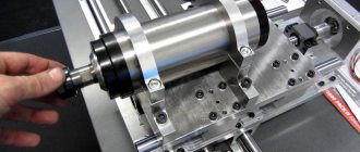
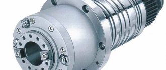
Machine spindle units
The spindle is made in the form of a massive rotor, with a mounting collet located inside it, and at the upper point of the cavity formed by two counter-facing conical surfaces, a working fluid intake (catcher) is installed. This spindle design improves working conditions on the machine.
Fig. 1 – Spindle of an electric spark machine
In the sliding bearing 1 there is a spindle 3 rotating through a V-belt drive 2, made in the form of a rotor, in the concentric bore of which a collet 4 is located on a tense or tight fit, for fastening along the outer surface of the workpiece 5. The internal cavity of the rotor is formed by two counter-facing conical surfaces 6 and 7, The working fluid supplied from the hydraulic pump through tube 8 into the hole of the workpiece, under the influence of the centrifugal forces of the rotating spindle, is collected at the periphery of the internal cavity (pocket) of the rotor, from where through the intake 9 through tube 10 it enters the filter element of the hydraulic pump.
Technical specifications for the design of a homemade machine
To make a homemade electrical discharge machine, you need to make a number of devices that will help automate the production process.
- A frame is needed; the mechanism for moving the electrode will be placed on it.
- You will need a mechanism that allows you to periodically bring and remove the electrode to the material being processed.
- To burn holes of different shapes you need to have a set of electrodes. Experts recommend using molybdenum wire.
- For different types of main tools, you will need to change the device power and amperage. Under different operating modes, the electrical circuit diagram must allow regulation of the discharge value on the electrode. It is necessary to provide for a change in the voltage ripple frequency.
- To cool the part (hardened steel cannot be overheated; tempering occurs with a decrease in hardness), coolant must be supplied to the work area. More often, ordinary water or salt solutions are used. The water simultaneously washes away sludge (destroyed metal particles).
Attention! In industrial installations, for example, the Japanese machine tool manufacturer Sodick uses baths made of impact-resistant glass. They organize the flow of liquid into the treatment zone, as well as the removal of waste water and subsequent filtration.
How to improve the machine?
The simplest machine made is a working model. Its purpose is to create holes in hardened parts.
In the future, you need to consider the option with a vertical electrode arrangement. Then you can install a bath underneath it. The process will occur without possible malfunctions associated with the presence of sludge that cannot be removed from the working area.
It is also necessary to consider additional mechanisms for smooth tool feeding. It may be necessary to carry out not only axial movement, but also movement of the electrode in the horizontal plane in order to carry out three-dimensional surface treatment.
Any simple machine gives ideas on how to further improve it and create a more convenient unit. The main thing is to take the first step and try to make the first sample.
Video: homemade electric spark machine.
Source
Do-it-yourself electric spark spraying
To change the shape and size of a metal workpiece, you can use the electrical discharge processing method.
It has been used for many years in various industries, characterized by high accuracy but low productivity.
To apply this processing method, you should use a special electric spark machine, which you can purchase or make yourself.
The homemade version can be used in everyday life in small-scale production. The cost of making it yourself will be lower than purchasing an industrial version.
Therefore, let’s take a closer look at how you can make the electric spark machine in question with your own hands, what you need for this and in what cases it can be used.
Homemade electric spark machine
The principle of the considered processing method
A special feature of processing with an electric spark unit is that the evaporation of metal occurs due to the effect of a certain charge on the surface of the workpiece.
An example of such an effect is the short circuit of a capacitor on a metal plate - a hole of a certain size is formed.
EDM creates a high temperature that simply evaporates the metal from the surface.
It is worth noting that a machine from this group has already been used over the past 50 years in various industries.
The main condition for using such an electric spark machine is that the workpiece must be made of a certain metal. In this case, it is not the degree of machinability that is taken into account, but the electrically conductive properties.
Main structural element
The EDM machine has a spark generator that acts as a capacitor.
For processing, a large capacity storage element should be used.
The processing principle is to store energy over a long period of time and then release it over a short period of time.
The laser device also works on this principle: reducing the time period of energy release leads to an increase in current density, which means the temperature increases significantly.
Electrical circuit of an electric spark installation
- the diode bridge rectifies industrial current with a voltage of 220 or 380 Volts;
- the installed lamp limits the short circuit current and protects the diode bridge;
- the higher the load indicator, the faster the charging of the electric spark machine;
- after charging is complete, the lamp will go out;
- Having charged the installed storage device, you can bring the electrode to the workpiece;
- after the circuit is opened, the capacitor begins to charge again;
- The charging time of the installed storage element depends on its capacity. Typically, the time period is from 0.5 to 1 second;
- at the moment of discharge the current reaches several thousand amperes;
- the wire from the capacitor to the electrode should have a large cross-section, about 10 square millimeters. In this case, the wire must be made exclusively of copper.
The generation frequency when the electrode is supplied to an electric spark machine is 1 Hz.
Design of an electric spark machine
There are schemes that are quite difficult to implement. The scheme in question can be implemented with your own hands.
Parts for the installed generator are not in short supply; they can be purchased at a specialized store. Capacitors are also widespread, as is the diode bridge.
At the same time, when creating a homemade electric spark machine, the following points should be taken into account:
- on the capacitor the indicated voltage should not be less than 320 Volts;
- the number of energy storage devices and their capacity are selected taking into account that the total capacity should be 1000 μF. All capacitors must be connected in parallel. It is worth considering that the power of a homemade version increases if it is necessary to obtain a stronger spark strike;
- The lamp is installed in a porcelain socket. The lamp should be protected from falling; a circuit breaker with a current strength of 2 to 6 Amperes is installed;
- the machine is used to turn on the circuit;
- electrodes must have strong clamps;
- a screw clamp is used for the negative wire;
- The positive wire has a clamp with a copper electrode and a tripod for direction.
High voltage generator from a transistor liner
Hello, dear friends!
Today I suggest you assemble a high-voltage generator using just one transistor from a TVS-110PTs15 line transformer with an UN9/57-13 voltage multiplier from an old color TV. The circuit is quite simple, built on the principle of blocking a generator and contains a small number of parts. Circuit of a high voltage generator from a liner on one transistor
To assemble the generator, you will need one KT819G transistor, or an imported analog TIP41C, but it is best to use MJE13009, since this transistor can withstand current up to 12 A and, accordingly, will heat up less. Personally, I used MJE13009 in my generator. Be sure to coat the transistor with thermal paste and install it on a radiator, preferably with a fan.
You will also need two 5-watt resistors. At 100 ohms and 240 ohms, the resistors in my generator got very hot and I decided to glue a small radiator with “poxy-pol”. The most important part of the generator is the TVS-110PTs15 line transformer; it is possible to use TVS-90LTs5 and other similar ones from old color, black-and-white and even tube TVs.
Linear transformer TVS-110PTs15
A couple of additional windings need to be wound on the magnetic core of the transformer. Coil L1 contains 10 turns, wound with wire with a diameter of 1 millimeter. We wind coil L2 with 1.5 millimeter wire, 4 turns in total. Both coils should be wound in the same direction. The secondary high-voltage winding remains unchanged.
Line transformer TVS-110PTs15 with two additional windings
The voltage multiplier UN9/27-13 or similar also needs minor modification. It is necessary to remove two unused terminals on it, marked in the picture with red arrows, then isolate these places with “poxy-pol”. It’s not necessary to do this, but if you accidentally touch these conclusions during the experiment... Your hair will stand on end and it won’t seem like much, of course it won’t kill you with an electric shock, there are very few amperes there, but it can burn you. A 470 ohm resistor is installed between the line transformer and the multiplier.
Voltage multiplier UN9/27-13
The arrester is made of two wires with a diameter of 1 millimeter. The distance between the electrodes is selected individually. To power the generator, it is best to use a power source from 12 to 30 volts with a current of at least 2A.
High voltage generator. Arrester
After power is applied, a powerful arc appears at the spark gap. How to measure the voltage at the output of a multiplier without a kilovolt meter? It is generally accepted that 1 millimeter of arc is 1 kilovolt, the length of the arc is 15 millimeters, which means the voltage at the spark gap is approximately 15 kilovolts.
I would like to say a few words about safety precautions. A high voltage of several tens of kilovolts is supplied to the spark gap from the multiplier, so do not touch the spark gap with your hands to avoid electric shock; even after turning off the power, high voltage remains in the multiplier capacitors. Of course, it won’t kill you with an electric shock, because there are not enough amperes, but it will hurt and possibly leave burns on the skin.
Friends, I wish you good luck and good mood! See you in new articles!
I recommend watching a video about how a high voltage generator works.