Lightning patterns and tree silhouettes can be created using high voltage from the microwave power supply. This method of wood processing can be used to make beautifully decorated hangers, bedside tables, cutting boards and more. Using a lightning burner from a microwave transformer, you can create original crafts that will become a gift or an addition to the interior.
The beauty is that no two patterns will be the same; it is impossible to predict what masterpiece you will create next time. The main thing is to follow safety precautions while working and do not forget about precautions. After all, high voltage is dangerous for humans.
Preparing the microwave power source
It’s not difficult to find an old microwave that has long been out of order or is collecting dust in the closet as unnecessary.
If you or your friends don’t have a suitable option at hand, you can buy a used device on the radio market for pennies.
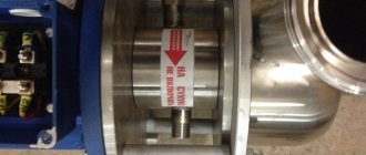
So, we’ve found the microwave, now it’s time to prepare a transformer from it. Carefully remove it from the device. The transformer has two windings:
- primary - wound with a thick wire;
- secondary - wound with a thin wire.
The network must be connected to the primary winding - we place two terminals side by side and supply 220 W to them. Electricity can be supplied either through a fuse or directly. If you choose the second option, make sure that the transformer does not overheat. The other two pins must be connected on the other side: one to the body (it can be soldered), the second to the plug. That's all, our device is ready. It's very simple. By the way, in the future you can put it in a plastic box and connect the wires to the buttons. This way, working with the transformer will be much more convenient and, most importantly, safer.
Universal charger
The operating principle is based on the conversion of sinusoidal energy from a 220-volt household network into rectified current, the value of which is regulated by an electronic unit.
Structurally, the scheme consists of three parts:
- a 220 volt input device that supplies voltage to the primary winding of the transformer;
- power unit made of thyristors and powerful diodes;
- electronic circuit for controlling the output current.
Let's take a closer look at them. As an example, I will show photographs of my own homemade device, made by wall mounting. For clarity purposes, some of the protective covers have been removed.
It was made about 10 years ago. It has proven itself well. But its electrical circuit was lost and I had to restore it from life in order to publish it on the website.
To accommodate all the parts, a piece of board with rubber soles was chosen to eliminate the slipperiness of the structure on problem surfaces.
220 volt circuit diagram
In the charger drawing, the supply voltage supply unit is highlighted in light red.
Installation method
The terminals are placed and the wires are connected on a 5 mm thick getinax plate. It is located on the back of the device, which limits accidental touching of live terminals. However, they are additionally covered with a plastic cover.
Power supply
A cord with a plug is used that can be inserted into any outlet. A voltage of 220 volts is supplied to the two outer terminals. There are four in total:
- the left pair is used to connect the fuse;
- middle - transformer windings;
- right - power buttons for 220 volts.
Fuse
I installed a design taken from a decommissioned tube high-frequency transceiver. You can use parts from an old TV or radio.
Purpose
Serves to protect the charger from accidental short circuits and overloads.
The need to install it was suggested to me by the actions of one driver, who again a month later brought me a factory charger for repair: I had to change the thyristors and diodes of the power unit. It turned out that he was checking their operation using the old-fashioned “spark” method, briefly closing the output contacts...
How to choose a fuse link
The protection is based on determining the current value, which ensures long-term operation at rated load and short-term overloads of up to 10%.
It can be calculated knowing the maximum power consumption and voltage. It was necessary to select the calibration wire for the fuse link using an experimental method: pass the test current from the load device through different samples and observe their behavior.
The selected wire was soldered inside the glass fuse body, and the stock made was put aside for storage.
Button
For continuous operation of the charger, a stationary jumper is simply installed on its terminals. It reliably bridges the contacts.
The self-return button is designed specifically for wood burning mode. It is mounted on the handle of the nichrome string holder and requires constant holding during operation. If you remove your finger, the tension is immediately removed from the entire device.
I believe that this technique increases the safety of using any electrical device. If a person slips or accidentally gets into an unpleasant situation, then a reflexive movement of the hand throws away the objects that are in it. The 220 volt voltage is automatically removed from operating electrical equipment.
I did the same thing with my electric trimmer during the repair, removing the long-term operation button from it.
Power LEDs
They are designed to indicate the applied voltage to the charger, located on the front and back sides of the unit, connected in parallel through a common resistor.
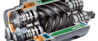
Transformer
I should immediately note that the design was created with a large reserve of power. Therefore, its dimensions have been increased. You can create a smaller charger.
The cross-section of the magnetic circuit is 3.3x6.3 cm.
How the calculation was performed
A detailed technique is given in the article on repairing a Moment soldering iron.
The iron has a rectangular profile. Its cross-section is 20.8 cm square. It allows you to transmit power of 430 watts.
I have planned a current of 10 amperes and a voltage of 24 volts in the output circuits, that is, a power of 240 watts. The margin is obvious.
I won’t take efficiency into account: it’s not critical. A current of 240/220 = 1.1 amperes will flow through the primary coil. This allows you to calculate the diameter of the wire.
d1=0.8∙√1.1=0.84 mm.
The micrometer shows almost a millimeter.
For the secondary winding, the wire diameter is d2=0.8∙√10=2.5 mm.
In the photo the diameter is 1.8 mm. Area 2.5 mm square. I wound it in two threads, creating a total cross-section of 5 squares. Which is quite enough.
I determine the required number of turns.
ω'=45/20.8=2.16 turns per volt.
In the primary winding there will be 2.16x220=475, and in the secondary: 2.16x24=52.
Description of design
The winding coils are made of electrical cardboard. There is enough space in them. The wires are insulated with varnished cloth.
After assembly, the secondary winding turned out to have 28 volts instead of 24 when the power supply was 220. The approximate calculation method and the quality of the assembly had an effect.
Power block
The installation is carried out on a getinax plate 8 mm thick. Its design includes:
- two thyristors KU202N;
- pair of diodes D242;
- output terminals;
- ammeter for monitoring load current.
Thyristor KU202N
This brand of semiconductor device just happened to be at hand. For my purposes, you can get by with any other one with a lower voltage of 100 volts. Pay main attention to the current: 10 amperes.
The thyristor is tested with current during operation.
Diode D242
Ten-amp semiconductors work as part of a diode bridge, acting as a buffer arm for thyristors.
Heatsinks for semiconductors
Since the loads on the bridge during its operation are large, it is necessary to take measures to effectively remove heat from it. Therefore, I place diodes and thyristors on radiators with a free air supply to them.
Factory-made radiators were suitable for the diodes, but for the thyristors I had to make my own cooling from a thick aluminum busbar.
Output terminals
The first photo shows that they use factory clamps from the power supply, which allow you to insert plugs with wires into nichrome holders or connect flat contact plates with cutouts.
Ammeter
To monitor the current value, an M494 microammeter taken from decommissioned equipment was installed. Its 100 microamp scale has been moved to a new reading: 10 amperes.
To do this, simply install a homemade shunt made of a thick brass plate on the output terminals.
To calibrate the device, it was necessary to assemble an electrical loading circuit and adjust the shunt parameters.
For this purpose, I ensured that the current from a load device of 10 amperes, controlled on the scale of a reference ammeter, coincided with the readings of a homemade device (a microammeter with a connected shunt) at the scale mark of 100 divisions.
In principle, the scale can be rewritten, but for me a sticker with the designation 10 A is enough. It is easy to calculate, for example, that 50 divisions are five amperes. That is, we simply divide the readings by 10.
When setting up the device, it is worth checking it at all control points. However, too high precision is not required for our measurements.
When adjusting experimentally, the shunt itself has to be changed in length or width: it can simply be filed with a needle file.
Thyristor operation control circuit
The electronic unit of my charger is powered by electrical energy from the secondary winding of transformer TP1. She:
- straightens up;
- stabilizes;
- converted by a generator;
- transforms into two streams;
- is supplied by individual lines to the circuits of the control electrodes of the thyristors.
The operating principle of such a circuit is described in detail in the article on transformer welding of electrical wires made of copper. Check it out. It's the same here, but the differences lie in the element base and its settings.
Straightening
The circuit uses a diode bridge made by the KTs402Zh assembly. There is no point in specifically looking for it: I used what was nearby. It rectifies a current of 0.6 amperes. This is more than enough for the control circuit to operate.
Voltage stabilization
To ensure a stable power level of 22 volts, it was necessary to connect three zener diodes in series. Marky saw two of them and marked them on the diagram. I don’t remember the third one, the inscription on the body has been erased. In principle, this is not important, because when setting up the charger, you will still have to select them yourself or use the KREN assembly.
Phase pulse generator
All parts and their values are shown in the diagram. I would like to focus on transistors.
KT203
The pinout and designations are shown in the picture. pnp structure.
KT315
NPN structure transistor. Its body can be confused with the KT361 (pnp) transistor.
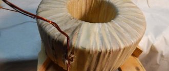
Pulse transformer
The magnetic guide is a permalloy ring with an outer diameter of about three centimeters. Three windings are wound on it. I have not experimented with other materials, including ferrite.
Each winding contains 50 turns of insulated copper wire with a diameter of 0.2 mm. To save installation time, I wound all the windings at once with one bundle of three threads. I put multi-colored cambrics on the beginning of each wire and secured them with one knot. In this way, I marked the beginning of each wire, which makes it a little easier to subsequently connect the transformer terminals to the electrical circuit: it’s easier to call it this way.
The finished windings were insulated with varnished cloth and covered with a metal casing for protection. The transformer was secured to a fiberglass board with a through screw and nut.
Setting up a pulse transformer
When installed in a circuit, the primary winding is selected arbitrarily and connected to the output of the phase-pulse generator.
The remaining two windings are mounted taking into account the polarity of its ends. This is where the beginnings of the veins, marked by nodes, come in handy. Their outputs serve to supply high-frequency pulse current to the thyristor through the control electrode circuit.
Installation of this section should be done carefully. For the circuit to work properly, mistakes cannot be made. If you have an oscilloscope, then they should compare the correspondence of the signals issued by the primary winding and the polarity of the pulses arriving at the control electrode of each thyristor. This will facilitate normal regulation of the amount of current through the terminals of the power unit.
Finding the right tree
Not every type of wood will have scorched designs that look beautiful and original. To make the picture attractive, it is worth spending a little time searching for suitable wood. This can be done experimentally. Some craftsmen like to work with thinner materials, others with thicker ones.
By the way, the future design also depends on the thickness of the tree. Many experienced burners advise choosing thin plywood. But who knows, maybe you'll like something different.
Homemade wood burner.
I somehow decided to make a homemade burner based on the model of the Soviet burner “Vyaz”. Back in the 90s, they gave me an “ELM” wood burner for my birthday . As I remember now, the orange body is exactly like in the photo below (photo from the Internet). But at that time my interest was not in the burner , but rather in how it worked. In short, over time, I destroyed it to the point of “kantsur” in childhood, now not understanding why. As they say, all that remains of the goat are the horns and legs - only the transformer has survived to this day. And now, after eleven years, I decided to correct what I had done and assemble a remake of this wonderful burner . I wanted to make a burner with my own hands practically from scratch . Only here is the power regulator - it was not possible to get a wirewound potentiometer, and in its place I used a lighting brightness regulator - a simple Chinese dimmer on a triac.
How to increase the conductivity of wood?
In order for the burning to end successfully and you get an interesting picture, you need to think about how to increase the flow of electric current through wood. To increase it, just apply water to the top layer of the canvas. But water itself will not be a good conductor. Therefore, either baking soda or table salt is added to it. An excellent result can be achieved using the following concentrate: per glass of water 1 tbsp. spoon of soda. When the solution is ready, it needs to saturate the surface.
IMPORTANT! The result of burning depends on the amount of impregnation. The more liquid, the brighter and clearer the lightning.
Once the wood has been soaked, set it aside for a moment to prepare the transformer.
Wood burner diagram.
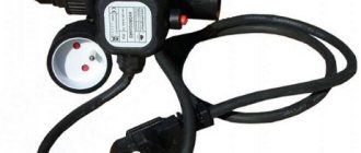
The wood burner is assembled using a simple dimmer circuit, the load of which includes a step-down transformer 220/4 volts .
In principle, you can buy a regular dimmer - a regulator for incandescent lamps for indoor lighting. Its diagram is identical to the one shown here.
The transformer was taken from the original old ELM burner - 220/4 volts. However, you can use a similar transformer or wind it yourself, using a wire about 1.5 mm in diameter for the secondary winding. Select the number of turns experimentally so that the output is 4 volts.
Installation is carried out using a hinged method, without the use of any board. A power switch and a variable resistor for adjusting power (in our case, the temperature of the burner tip) are attached to the front panel of a homemade burner The installation is actually done at the switch and variable resistor terminals.
The triac is installed on a minimal radiator.
Transformer connection
Now everything is ready to go. All that remains is to connect the transformer (it is important to do this correctly) and start burning. Once again, make sure that the transformer is connected correctly, if everything is in order, connect its positive and negative leads to the ends of the plywood. If possible, turn on the fan, which will protect you from a sudden fire, and will also give you the opportunity to see the result of the discharges - the picture is mesmerizing.
DIY Lichtenberg figure generator
OK
Warning! The work is carried out using a lethal level of tension; you should not start if you do not have complete confidence in your abilities. This tutorial shows how to make a Lichtenberg generator from an old microwave oven, which is a fairly powerful device that can create beautiful arcs of plasma and burn amazing patterns into wood.
Materials and tools for homemade work:
- an unnecessary microwave; - screwdrivers; - wires, a rod of screws, a piece of board or block; - baking soda, water... The process of making a homemade product:
Step 1: watch the video
The video above gives the most complete explanation of how it works. Likes and comments are welcome.
Step 2: Find a microwave for materials
To begin with, the author makes sure that the stove is unplugged, then removes the metal casing. This is quite simple, as you only need to unscrew the screws. The process of opening a microwave oven is quite complicated, because inside the case there is a powerful capacitor that carries a lethal charge of electricity. It should first be carefully de-energized or unplugged, disconnected from the stove, and then removed away. Step 3: get the transformer The transformer is a necessary component of the future design. It will be relatively easy to get it, since the transformer is attached to the housing only with screws.
Step 4: New Transformer Wiring
The author removes the mains plug from the back of the stove and connects its positive and negative ends to the two inputs of the primary winding coil. Polarity doesn't matter. He then connects one end to the secondary coil and the other to a metal body that will conduct electric current to the wooden block.
Step 5: Enjoy the Show
You should connect both wires with either two screws or nails driven into a wooden block. Then the author mixes two spoons of baking soda with a large mug of water and pours this mixture between the electrodes, connects the structure to the network and moves away. When the generator is connected to the network, you should not touch it, the electrodes or the wood, as this can be fatal. Before approaching the block, you need to turn off the generator from the network. Source Become the author of the site, publish your own articles, descriptions of homemade products and pay for the text. Read more here.
OK
Rate this homemade product:
3 To write a comment you must log in to the site via social media. networks (or register): Regular registration
Information
Visitors in the Guests group cannot leave comments on this post.
usamodelkina.ru
Cleaning and finishing
When the painting has cooled, examine it. Beautiful, isn't it? But this is not the final result yet. The burnt wood still needs to be sanded. During grinding, excess material, in particular charred material, will be removed. After sanding, rinse the painting under running water. To protect the drawing, it is advisable to cover it with a thin layer of varnish. Some artists also place luminescent material in the zippers, making elements of the painting glow in the dark. It looks gorgeous!
Burner body.
The body of the burner is made of 10 mm plywood. The necessary parts of the body were cut out with a jigsaw, the ends were sanded with a belt sander to the size required for assembly, coated with PVA glue and tightened with self-tapping screws with countersunk heads. Drying for about a day. After drying the body, the parting plane of the two halves – the cover and the body – was polished with a surface grinder. The body and lid are mounted on miniature canopies. This entire assembly is also processed by a belt sander to a single form - factor with the removal of a certain certain amount of chips. As a result, we have an excellent homemade housing for the burner with a well-fitted parting plane and smooth sides.
We open the body of the burner several times until the desired shade is obtained.
Dry the body. As the stain dries, the wood fibers rise to form a velvety surface. Such a surface cannot be opened with varnish. Expanded wood fibers will look terrible. The body needs to be polished. To do this, we take a small wooden block that is convenient to hold in the hand, press its corner against another piece of wood, and then rub it on the wooden body. That is, we rub the body with the rounded corner of the bar - as if we are crushing the swollen fibers raised by the stain. Polishing should be carried out along the direction of the wood grain using uniform moderate force over the entire surface of the body. The process is long and painstaking, but the result is worth it. It is also recommended to first practice on a sample to prevent damage to the burner in the absence of experience.
After finishing polishing, we coat the body with varnish. I recommend semi-matte parquet varnish. It gives a great look and scratches will not be so noticeable in the future.
Source
Operating principle, features and connection diagram of a lightning burner from a microwave transformer
Lightning patterns and tree silhouettes can be created using high voltage from the microwave power supply. This method of wood processing can be used to make beautifully decorated hangers, bedside tables, cutting boards and more. Using a lightning burner from a microwave transformer, you can create original crafts that will become a gift or an addition to the interior.
The beauty is that no two patterns will be the same; it is impossible to predict what masterpiece you will create next time. The main thing is to follow safety precautions while working and do not forget about precautions. After all, high voltage is dangerous for humans.
Preparation of materials for manufacturing
To make a home burner you need to have a minimum set of tools and components.
To make a pyrograph you will need:
- Wooden glazing bead 10 cm.
- Duct tape or electrical tape.
- The electronic unit is no less than 5 Volt 2A.
- Nichrome thread.
- Soldering iron.
- Electric drill with suitable drill bit.
- Flux for soldering.
- Solder is tin.
The manufacturing process begins with the preparation of all tools and necessary materials. First you need to find a nichrome thread, which can be sold at any hardware store. If there is no thread on sale, the material can be obtained from an old electric soldering iron.
You will need to disassemble the heating part of the electrical appliance. The nichrome thread is located on the “tip” of the soldering iron under a metal casing and is easily removed by winding without the use of third-party tools.
Features and types of equipment for wood burning
A transformer for a simple burner, which is used for domestic purposes, that is, not in production, for entertainment, as a hobby, has minimal power and voltage ratings. The voltage values should not be less than 5 Volts, and the current strength should not be 2 Amperes. If the setting shown is less than this threshold, then burning will not work, since the power of the device is not enough to process even soft wood. Many novice fans of the branch of pyrography art are interested in what kind of transformer is needed for a wood burner. Experienced experts agree that it is better to use a reducing type, which has optimal characteristics.
How does the battery charge?
The car's battery, powering the on-board instruments and lighting, is discharged. When the engine is running, it is recharged due to the fact that DC electricity with a potential difference of 13.8÷14.5 volts is supplied to the banks with a total voltage of 12 volts from the generator through a relay regulator.
The power of a running generator significantly compensates for the energy lost by the battery. But not completely. Some part of its capacity is not replenished by the incoming charge current. This depends on many conditions, which are influenced by different operating modes created when the car is moving.
How to make a simple burner?
Few people have enough time to create a complex burner, so let's consider a simple option.
Materials
To assemble this device you will need the following:
- sewing needle;
- needle from a medical syringe;
- double wire.
The needle is very important as its quality will affect the quality of your masterpieces. It is better to choose a thin and sharp needle. The needle from the syringe will heat up to red during operation, and the sewing needle will lightly touch it - this will cause resistance and help warm up the needle.
Build process
To make a burner you will need a syringe needle cap and a sewing needle with thread. You need to pierce the cap with a needle and pull the thread to the end so that the needle rests on the cap. To secure it, wrap it with the rest of the thread, and the needle should go beyond the cap and be placed parallel to it.
Let's return to the syringe part. We don't need the cone-shaped cap - we remove it. We wind the needle to the opposite part of the cap with another thread and a sewing needle. Now slightly bend the tip of the needle so that its tip barely touches the sewing needle. As we said, the smaller the contact area, the faster the burner will heat up.
Nutrition
We take a good double wire - it should be stripped on both sides and two holes should be made in the cap to bring the wire out. After this, connect each wire to the needles - screw them as tightly as possible, since the quality of current flow will depend on this.
For quality and safety, finally secure the wire with electrical tape.
Finally, use an unnecessary button, for example, from an old tape recorder, and a battery. The main thing is not to reverse the polarity, otherwise the device will not warm up.
Safety precautions
All components of the burner, with the exception of the tip, the secondary winding and the cable connecting them, are under voltage of 220 volts. You can touch them only after unplugging the power cord from the outlet.
When using nichrome/fechral needles of different diameters, you have to adjust the power for each needle. In my version, I got it with a dimmer with a housing. And if you create from scratch, then the easiest way is to take a ready-made dimmer, for example. The price will actually be higher than soldering it yourself, but it will save time.
As for the needle holder, the kit included 2 holders made of copper tubes with crimped nichrome needles. I left one unchanged, and removed the needle from the second and put brass bushings without insulation on top of the copper tubes with 2 screws from a regular terminal block. I inserted steel wire into the tubes so that they would not be pressed through by the screws.
If you repeat the design, then there are ceramic terminal blocks and, as an option, connectors for halogens. You can take them more powerfully, but most likely the needle/tip will not be fixed very firmly in it.
The more reliable the contact, the less heating. A compromise is needed between contact reliability and the ability to change needles. It would be nice to choose a wooden or, best of all, cork handle.
In general, I gave you the idea, and the specifics of implementation when making a homemade wood burner are up to you. Especially for the Radio Circuits website - cirkon .
Source