In its simplest form, a choke is a coil of thick copper wire wound around a magnetic core, which is connected to the output circuit of the welding machine in series with the electrode. A choke for a semi-automatic device is necessary to smooth out current ripples that occur during short-term changes in the input voltage and instantaneous short circuits on the electrode. When performing semi-automatic welding without this device, there is a high probability of weld defects occurring, since with such deviations in electrical parameters, the wire continues to feed at a constant speed.
Any home craftsman can make a choke for a semi-automatic machine. Its calculation is carried out in a very large scale (mainly in terms of wire cross-section), and the parameters of a homemade choke are selected by adjusting the core gap during trial activation of the semi-automatic device in different modes. However, it is still advisable to have at least a general understanding of the basic electrical principles underlying the operation of this device, as well as the design features of its manufacture.
Figure 1 - Choke for semi-automatic
Principle of operation
The operation of the choke of a semi-automatic welding machine is based on the so-called “first law of switching”, according to which the current in the inductor cannot change instantly. In a very simplified form, we can say that the inductor acts as a kind of energy storage device, but unlike a capacitor, it accumulates not voltage, but current. When passing through the coil, the flow of electrons generates a magnetic field, the magnitude of which depends not only on the current strength, but also on the parameters of the core. By adjusting the gap between its elements, you can control the magnitude of the magnetic flux and thus regulate the inductive reactance of the inductor.
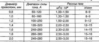
The inductance value of the inductor directly affects the rate at which the current increases during a short circuit. Moreover, it directly depends on the semi-automatic welding mode and the wire diameter. When using thin wire, a faster rise in current is required and, accordingly, less inductance than when using thick wire. For example, when the wire diameter is reduced by one and a half to two times, the inductance decreases by 2.5–3 times.
Markings and symbols
In circuit diagrams and technical documentation, chokes are designated by the Latin letter L, and the conventional graphic designation is in the form of semicircles. Their number is not indicated anywhere, but usually does not exceed three pieces. A bold dot placed at the beginning of the semicircles indicates the beginning of the turns. If the inductance is performed on the frame, a straight line is drawn against the image. To indicate the denominations of an element, a code of letters and numbers or color coding is used.
You might be interested in: The unit of measurement is kilowatt and what is measured in kW
The numbers indicate the inductance value, and the letter indicates the tolerance. For example, the code 250 J indicates an inductance equal to 25 μH with an error of five percent. When there is only a number on the marking, this means that the tolerance is 20%. Thus, the first two digits indicate the numerical value in microhenry, and the third is the multiplier. The letter D is placed on high-precision products; their error does not exceed 0.3%.
The color marking, in principle, corresponds to the alphanumeric marking, but is only applied in the form of colored stripes. The first two indicate values in microhenry, the third is the multiplication factor, and the fourth is the tolerance. The inductance of the inductor, which shows two orange stripes, brown and white, is 33 μH with a permitted deviation of 10%.
Purpose of the throttle
Welding using a semi-automatic machine is carried out with direct current of negative polarity on a wire, the thickness of which varies within 0.5÷3.0 mm. The smaller its diameter, the lower the welding current and the more stable the arc. During the welding process, the molten wire metal enters the weld pool in the form of a continuous stream of droplets. This ensures the stability of the arc and the quality of the weld. With the short-term formation of a continuous flow of metal, a short-circuit current occurs, and in the event of a break, it sharply decreases. If a choke is included in the output circuit of a semiautomatic device, then in the first case it prevents an instantaneous increase in the current, and in the second case it compensates for the drop in its value due to the “stored” energy.
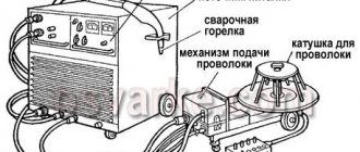
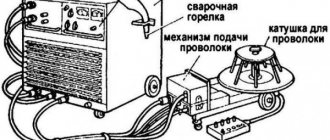
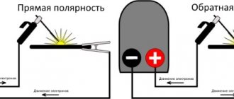
Figure 2 - Semi-automatic circuit diagram
Semi-automatic welding machines use chokes with fixed, stepped (see figure above) or adjustable inductance. The first type is used when welding in constant modes, in the second case the choke is made with several taps, and in the third the inductance is regulated by changing the size of the gap in the magnetic core or mechanical movement of the core. With an unstable external power source, the best option for a semi-automatic machine is gap adjustment, since it allows you to experimentally select a welding mode with a stable arc and without metal spattering. And the optimal method for solving the problem of stability and quality of the welding process is to use a choke in a semi-automatic machine in combination with a voltage boost circuit on the input transformer.
Self-production
To make your own throttle, you need to correctly calculate its design. To do this, use a simple formula for calculating inductance: L=0.01*d*w 2 /(L/d+0.44), where d is the diameter of the base (cm), L is the length of the wire (cm), w is the number of turns . Moreover, if you have a multimeter with the ability to change the inductance, then the exact number of turns can be selected using it.
The winding method using this formula involves laying turn to turn. For example, it is necessary to select a magnetic circuit for a choke with an inductance of one μH, designed for a current I = 4A. A 2000 NM core of standard size K 16 x 8 x 6 is taken. According to the reference book, the initial inductance coefficient is ALH = 1.36 μH, and the magnetic path length is le = 34.84 mm. Accordingly, the number of turns will be N= (L/ALH)0.5= (1/1.36)0.5 = 0.86. If we take N=1, then at a given current the magnetic field strength in the core will be equal to H= 4*1/(34.84*10−3)= 114 A/m.
Thus, the inductor is a coil characterized by inductance. Thanks to its properties, it can accumulate magnetic power and then release it into the circuit in the form of electrical energy. Moreover, the use of the element also makes it possible to suppress the alternating current component in the circuit.
How to calculate the cross-section of a winding wire
To calculate the cross-section and select a suitable wire, it is first necessary to determine the maximum current density.
Its value depends on the material of the conductor and the temporary operating mode of the semiautomatic device, which is determined by the passport value of the parameter PN (PV) - the duration of the load. The formula for calculating the current density based on the PN value looks like this: Here Jp is the current density in A/mm² for a given PN value as a percentage, and J is for long-term modes.
For copper conductors of transformers and chokes, J is usually taken to be 3.5 A/mm².
When using aluminum wires, it is necessary to apply a reduction factor of 1.6 (see table).
| Mon (%) | Jп | Mon (%) | Jп | Mon (%) | Jп | |
| Copper | 20 | 7.8 | 40 | 5.5 | 60 | 4.5 |
| Aluminum | 4.9 | 3.5 | 2.8 |
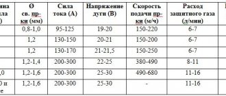
To determine the wire cross-section (S) for winding the choke of a semi-automatic device, it is necessary to divide the rated value of the maximum current (I max) by Jп. For example, with I max = 150 A and PN = 40%, the cross-section of the copper wire will be equal to 27 mm². The exact type of conductor (wire or busbar) is selected from a reference book, rounded up.
Figure 3 - Explorer
The number of turns is calculated using a formula using the dimensions of the core, which are also determined by calculation. But craftsmen, as a rule, do not do all this, because they assemble a choke for a semi-automatic machine based on an existing magnetic circuit. The usual number of turns for such a product at a current of 150–200 A is several tens (40÷60). Unlike the cross-section size, the error here is not very critical. In the worst case, it may result in poor weld quality.
Why is a throttle needed and how does it work? I show how to measure the inductance of various chokes
Among the electronic components on the board there is almost always a choke, also known as an inductor. Why is it needed and how does it work? In this article I will measure the inductance of various coils and explain how the inductor works.
An inductor (hereinafter referred to as an inductor) is a passive electronic component that allows energy to be stored in the form of a magnetic field. An inductor consists of a core and a winding. Do not confuse a coil and a transformer, as they differ in structure and perform different functions.
In fact, almost any conductor can be considered as an inductor, but often the inductance of other elements is infinitesimal and is therefore not taken into account.
The inductor is most often made in the form of a coil with a certain number of turns of copper wire around a cylindrical or toroidal core. Here are a few chokes that I desoldered from various devices:
Source: Own photo
Here is one of the main properties of an inductor:
Direct current flows almost unhindered through the inductor, while alternating current cannot flow through it.
This property allows the chokes to be used as filter circuits in switching power supplies, without allowing high-frequency pulses to pass into the household network. It's all about reactance, which has a significant effect on alternating current. This occurs due to the fact that the half-cycle current lags behind the voltage. If you apply a constant voltage to the inductor, it will pass through the coil, but not immediately, which will allow you to use a smooth switching on of the desired device, “smoothing out” the sharp impulse. The choke will store electricity in the form of a magnetic field for some time.
The inductor's ability to store energy is called inductance. The unit of energy that a choke can store is called 1 Henry. In order to measure the inductance of a coil or inductor, you need to have a special device - RLC Meter. Many modern multimeters can also measure inductance, but not mine. I use a separate open-frame device, which I already described earlier in the following article:
- Even a non-bloated air conditioner may be faulty. Checking capacitors with an ESR meter
I will use it to measure several chokes I have in stock.
Source: own photo
This element has a very small inductance, only 0.03 mH (Henry miles)
Source: Own photo
The coil is cylindrical in shape and has an inductance of 3.05 mH.
Source: Own photo
Here I measured the inductance of the coil from the relay from this article. As we can see, the relay has a higher inductance, as much as 2577 mH.
I tried to explain everything in simple words, but I hope your comments will help me supplement and expand this article. Feel free to write and criticize, I will be glad to receive any feedback from the reader.
What is required for production
In order to make a choke for a semi-automatic machine with your own hands, first of all you should make the required calculations, and then prepare the necessary materials and tools. During the work you will need:
- soldering iron (from 100 W) with accessories;
- bench vice;
- pliers, pliers, hammer, etc.;
- coil core and body;
- getinax (or similar) for gaps;
- varnished cloth;
- keeper tape;
- epoxy or glue;
- copper or aluminum wire (or bar);
- two screw terminals.
In addition, you need a block to secure the reel body, as well as pieces of any plastic or wood to wedge it.
Step-by-step instructions for assembling a throttle with your own hands
To manufacture a welding choke, no diagrams or drawings are required.
Everything is quite clear and obvious, you just need to know how many turns and what wire to wind. Any set of transformer iron can be used as a core, up to a package of rectangular plates. However, the best option would be to use a PL type core, since it is assembled from two monolithic C-shaped halves and the gaps between them can be used to adjust the inductance of the future inductor. Such cores have been widely used and are used in power supplies for radio equipment since Soviet times. Therefore, finding an old transformer (for example, TC type) with a power of 200–300 W will probably not be a very difficult task. It is also very convenient for adjusting the gap that such a core is tightened with a special clamp with a screw connection (see figure below).
Figure 4 - Core
You can use any wire or bar (but copper is still better), the main thing is that the cross-section corresponds to the design one.
Winding and installing the choke
When disassembling an old transformer, you must very carefully remove the coils, free them from the wires and clean the junction of the core halves until shiny. The following sequence of actions looks like this:
- Place the reel on a wooden block, secure it with a vice and wrap one or two layers of keeper tape around the reel, and varnished cloth on top of it. Then carefully wind the first layer of wires, turn by turn (you will get about 8–12 turns, depending on the thickness and gaps). You must act very carefully, because the wires are hard, and the coil is made of thin and fragile getinax.
- Wrap varnished fabric over the first layer of turns, having previously coated it with varnish. The classic option is bakelite varnish, but you can use any other one, for example parquet. Wind a second layer of turns, also cover it with varnish and varnish. Carefully bend the output end.
- Do the same with the second coil, then dry both of them thoroughly. Prepare two plates of getinax (or other insulating plastic) 1–2 mm thick according to the size of the joint of the core halves.
- Place both coils on one of the core halves, place insulating pads and insert the other half. Carefully tighten the core with a clamp.
- Connect the coils in series by twisting with soldering or a screw (pre-tinned), and then insulate the connection point.
- Fix the ends of the coils intended for connection on the clamp, and then solder the terminals to them.
When checking a choke with a semi-automatic device, you need to try it in different modes, and, depending on the situation, increase or decrease the inductance by replacing the gaskets in the core gap.
In the famous book by V. Ya. Volodin “Modern do-it-yourself automatic welding machines,” a classic calculation of the number of turns in the inductor winding is given. For a home craftsman, a more simplified version of determining the number of turns would be suitable, even if their number is approximate. If anyone knows sources with such techniques or can describe how to do it themselves, please share them in the comments to the article.
DNAT choke types and connection methods
In order to ensure ignition and equalization of the current of sodium lamps, both high and low pressure, when the lighting devices are connected to the network, a dnat choke is used, which includes ballasts and ballasts. These are the main devices, without which the use of sodium lamps is not possible that is inappropriate, but simply meaningless. In addition to the ballast, it is also necessary to purchase a pulsed ignition device, abbreviated IZU, which allows you to heat the lamp, using a pulse that allows you to create a discharge in the gas mixture.
Currently, two-winding chokes are considered obsolete, so they are used quite rarely. The ballast can be purchased both domestically and foreign; this statement also applies to the pulse ignition device. The main condition is that the power of the inductor and IZU must correspond to the power of the sodium lamp.
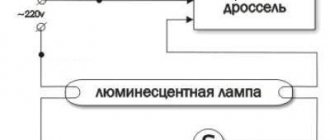
Choke for fluorescent lamp.
We note the fact that a pulsed ignition device (IZD) can be of two types. The first type includes two-wire IZUs, the second type includes IZUs with three wires. Accordingly, three-wire devices are more reliable, but at the same time their price is more expensive, so the question comes down to the economic feasibility of purchasing the product. The next term that refers to the concept of a throttle is ballast. Ballast is usually called a ballast and a pulse starting device, which have a metal body.
There are also open rights. The choice of an open or closed device depends on the preferences of the individual electrician. The advantages of lights in a metal case include a lower operating temperature, manufacturer guarantees regarding the assembly of the product, and a simpler installation scheme in lighting fixtures. Let's look at the dnat connection diagram. So, the main condition is that the power of the inductor matches the power of the lamp. For example, if you have a dnat choke of 600, then the sodium lamp should also be 600. The rule is simple, but if it is not followed, the operating life of the lighting device will be significantly reduced, and the light output will drop to a critical level.
The next point that you need to pay attention to is the installation diagram. In this case, it is necessary to take into account various parameters, among which we note the length of the wire from the lamp to the inductor. This distance should not exceed one meter.
Moreover, for connections it is necessary to use copper wire, monocore or stranded, with a cross-section of 0.75x1.5, although this is also an amateur question; you can take a wire with a larger cross-section, so to speak, with a margin. Pay attention to the issue of purchasing a power cord, it must also withstand heavy loads, the cross-section should be about 1.5 - 2.5 mm, even if the choke for dnat is 150. Approximate parameters of the choke are shown in the table below.
Table of calculations of the main properties of the inductor.
The next point we pay attention to is the need to install a fuse. Many will argue that this is a waste of money, but this statement is not true. The fuse, like a faithful guardian, will save you in the event of a breakdown of the ballast, when various troubles are possible, which can result in either a lamp explosion, a fire, or the banal knocking out of plugs if you do not have the bugs screwed on. It is best to purchase a two-pole machine, it is more convenient so as not to bother with how to insert the plug into the socket.
Worth reading: everything about electrolytic capacitors.
Moreover, the choice of machines must be approached with the utmost seriousness. As well as the purchase of other parts, such as a Dnat 250 throttle, ballasts or a pulse ignition device. Therefore, it is necessary to buy components exclusively at retail outlets that do not sell defective illiquid goods.
It will be interesting➡ Diode bridge - what is it?
At the same time, it is better to overpay and buy a normal automatic machine or choke than to underpay and buy HPS control gear produced by Chinese industry. So that later it doesn’t work out, as in the Russian proverb: the miser pays twice. The connection diagrams for all the devices indicated in the article are different in each specific case, so it is necessary to use the services of a professional electrician who will perform the work efficiently.
Throttle on the diagram.