Specifications
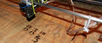
This laser engraver is equipped with a 1.8W 445nm laser module, of course, this is nothing compared to industrial laser cutters that use lasers over 50W. But this laser will be enough for us. It can cut paper and cardboard, and can engrave all kinds of wood or plywood products. I haven't tested other materials yet, but I'm sure it can engrave on many other surfaces. I’ll go ahead and say that it has a large working field measuring about 500x380 mm.
Who can make such a laser machine? Everyone, it doesn’t matter if you are an engineer, a lawyer, a teacher or a student like me! All you need is patience and a great desire to get a really high-quality machine.
It took me about three months to design and build this engraving machine, including about a month of waiting for parts. Of course, this kind of work can be done faster, but I am only 16 years old, so I could only work on weekends.
Design of engraving machines
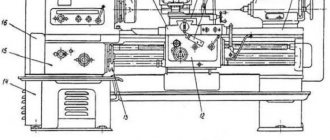
Laser engravers belong to the category of high-tech equipment. In addition to laser technology, their operation is ensured by optical devices, control programs and automation of control of performed actions. The following structural elements are common to all laser engraving devices.
- Ensuring precise positioning of the laser beam relative to the object being processed is guaranteed by the coordinate table. It is a frame on which guides are installed. The accuracy and smooth movement of the moving elements of the engraver depend on the quality of execution of this unit.
- The machine drive includes microstepping motors or servos that provide movement to the moving parts. Their peculiarity is that, depending on the nature of the current signal, they can change the speed of movement, direction of rotation, and number of revolutions. The force from the motors is transmitted to the moving mechanisms using belt drives or a ball screw.
- The work table acts as a base device for engraved objects. Most of them are carried out by lifting (manual or automated) in order to achieve a better technological position between the part and the laser head. Depending on the shape and properties of the materials of the objects being processed, the tables have design features (aluminum slats, honeycomb elements, in the form of thin pointed rods, and others).
- The optical system ensures the desired direction and focusing of the beam. Using a system of mirrors made of a special material that prevents scattering, the beam is delivered to the focusing lens. It compresses the entire energy of the beam into a diameter of several tens of millimeters.
- Actually the emitter itself, which, for example, in a gas laser consists of a lamp and a pump unit. A laser lamp consists of three cavities located in glass, metal or ceramic housings. The internal and external cavities are filled with carbon dioxide or its mixture with nitrogen and inert gas. The middle cavity is used for cooling with water or other special liquid. High voltage is applied to the electrodes located inside the internal gas cavity, allowing the tube to generate laser radiation.
- The pumping unit helps set the voltage and current required to form the laser beam.
- The engraving area must be cleaned of combustion products (traces). They should not settle on the surface of the lens. This function is performed by an air compressor, which is an integral part of the laser engraver.
Interesting: Laser engraving of metal
Laser machine for engraving and marking MiniMarker 2-20A4.
- Some materials produce large amounts of smoke when engraved. To eliminate it, the device is equipped with an exhaust fan with corrugated sleeves.
- While the engraver is operating, the lamp heats up. Overheating can quickly cause it to fail. A container with distilled water with a water pump immersed in it is an integral attribute of a laser engraver.
- The machine control system is an electronic unit that sends commands to drive motors, a laser emitter, air cleaning and cooling systems, and others. Teams are formed by software designed to perform a specific type of engraving work.
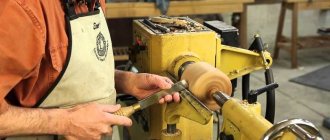
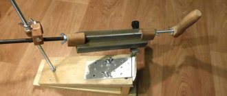
- For engraving on rotating surfaces, the machine is optionally equipped with a special rotary device, similar to that found on a lathe. It consists of a cylindrical clamping device and a stop - a centralizer, moving on the slide of the engraving machine.
Required materials for assembly
It's clear that you can't make a laser engraver without the right parts, so I've put together a specification sheet with almost everything you need to make one. Almost all parts are purchased from Aliexpress because it is cheap and there is free shipping on most items. Other parts such as machined rods and MDF sheets (can be made from plywood) were purchased from a local hardware store. The laser and laser driver were ordered from ebay. I tried to find the lowest prices for all parts (not including shipping).
It took a lot of time before I came up with this design. I made a few others first, but this one was truly the most beautiful of all the others. First of all, I drew all the details in a graphics editor and printed them in natural size. I assemble the entire engraver from MDF sheets 18 mm and 12 mm thick. We also chose this design because we could easily attach a Z axis and tool, turning our machine into a milling machine.
Of course, I could have made a different, simpler design... But no! I wanted something special!
Build process
After printing out the drawings, I had parts that needed to be put together. The first thing I did was install the electronics housing door on the left side and the hinge lock (the door installed without difficulty, so I did that first. To assemble the electronics housing, I used a lot of L-shaped iron brackets with holes for self-tapping screws If the body is planned to be made of plywood, then you must first drill holes in it for self-tapping screws.
First, the left side of the electronics housing was taken back and the front and back of the housing were installed on it using brackets. I did not use screws or nails to install the cover and control panel, but screwed the same brackets to the walls and simply placed the cover and panel on them so that there would be no inconvenience when installing the electronics in the future.
After setting the electronics housing aside and taking the base plate and X-axis support parts, you need to install them as shown in the photos, making sure that the X-axis and motor mount are on the right side of the CNC machine. Now you can safely install the electronics housing in the same way as shown in the pictures.
Next, two 700 mm shafts were taken, two linear bearings each were strung on them, and they were fixed on the machine itself using special end supports for ground shafts. At this stage, this is what I got:
Put this half of the laser machine aside for a while and work on the moving part X, and support the Y axis and attach the shaft support to the moving part of the X axis with nuts and bolts and attach the support to the X axis with two nuts.
- Now take two 500mm shafts, put one linear bearing on each shaft, put a shaft support on each end of each shaft and install them on the machine.
- Attach the Y-axis running nut to the Y-axis moving part with nuts and bolts, and screw it to the linear bearings with self-tapping screws.
- Attach the lead screw and stepper motor.
- Connect the whole thing to the other half of the engraver and attach the lead screw and stepper motor.
You should now have something similar to what is shown in this photo:
Development of the base and X-axis
The base was made of wood. The most important part is to make sure that the two X-axis guides are parallel. Instead of using two motors to move along the X-axis or using a complex belt/pulley system, a separate motor was used for the X-axis and a drive belt centered on the Y-axis. It looks a little awkward, but the system is simple and works well.
In the first stage, the cross beam that connects the belt to the y-axis was held on with simple superglue. Not the best solution, which we later had to abandon and print special brackets for fastening on a 3-D printer.
idler plate.stl
conclusions
This is, perhaps, all the information that he conveyed to us, but this is a pretty good instruction for those who have a dream of assembling with their own hands a good homemade laser machine for home and hobby purposes.
The assembly of the laser engraver itself is not particularly expensive, since the number of parts is minimal, and their cost is not particularly high. The most expensive parts are probably stepper motors, guides and, of course, parts of the laser head itself with a cooling system.
This particular machine deserves special attention, since not every laser engraver allows you to quickly install a milling machine on the 3rd axis and turn the machine into a full-fledged CNC milling machine.
In conclusion, I would like to say: if you really want to assemble a high-quality CNC machine with your own hands, which will serve faithfully for many years, you do not need to save on every detail and try to make the guides smoother than the factory ones or replace the ball screw with a stud and nut. Although such a machine will work, the quality of its work and the constant adjustment of mechanics and software will simply frustrate you, making you regret the time and money spent on it.
Our ancestors were engaged in stone processing in ancient times. This culture has survived to this day, but working with this material has become much easier and more convenient, thanks to innovations and modern machines. A desktop laser engraver for stone makes your work easier and allows you to make clear drawings on any type of stone.
A laser machine is a convenient and fast way to apply any image to a stone, thanks to which you can make a pattern of any complexity, even those that you cannot create with your own hands. With the help of an engraving printer you can open your own profitable business. But how much does such a machine cost, and what models are popular?
Stone engraving machine
Today, many companies produce good quality laser machines. Each of them has its pros and cons. The table describes the models of the best manufacturers and prices.
These are the most popular models that allow you to start your own business providing services related to stone engraving. But not everyone has the opportunity to purchase such equipment right away; in this case, you can start your own business with a machine made by yourself. A laser engraver made from a do-it-yourself printer is the best way to start a business with minimal investment.
How to make an engraver from a printer?
Making an engraving machine from an old printer is not difficult at all. Detailed instructions will help you figure everything out. But first you need to prepare all the necessary details:
- 3 studs from a hardware store;
- aluminum U-profile;
- 2 bearings;
- a piece of plexiglass;
- nuts of regular size and long;
- 3 stepper motors, they can be borrowed from an old printer.
In addition to this, you need to have the following tools on hand: a hacksaw, drill, jigsaw, bolts, screws, screwdrivers and other tools. The only thing that will need to be done outside the house is to weld the base for the machine, although it can also be made with a bolt-on mounting. Instructions on how to make a laser printer at home with your own hands are described in the table below.
| No. | Stages of machine manufacturing |
| 1. | The manufacture of the machine begins with fastening the lead screw and profile. The latter is used as a kind of sled. |
| The bearings are fixed using heat shrink, and soft plastic - an ordinary paper folder - is perfect for tightening. A plate in the shape of the letter “P” with a bolt is attached to the lead screw; it is necessary for fastening the X-axis plane. | |
| The motor on the X-axis is attached with lengths of studs. The axle is fixed with an adapter and a piece of rubber hose. It is screwed onto the running axle on one side, and the other end is fixed in the adapter. | |
| 4. | It is also very convenient and easy to mount the engine to the frame. |
| 5. | We make the platform from plexiglass, on which it is necessary to place a limiter made of a profile and a pressure roller. The area should be the size of the working area of the machine. |
| 6. | The Y axis is assembled identically to the X axis, the only difference is in the motor mounting, it must be attached to the X axis. |
| Correctly assembling the Y axis is not difficult, because it almost follows all the contours of the X axis, but only the pressure rollers must be fixed in front. The self-made engraving machine in this model can be an ordinary household Dremel. You can attach it using plexiglass. |
So the DIY desktop laser engraving machine is ready. Now all that remains is to connect it using limit switches. This homemade device allows you to carve stone at home, but does not allow you to cut it.
What stones can be engraved on?
Not every stone can be processed with an engraving machine; dark natural materials are best suited for engraving, such as:
- granite;
- marble;
- white marble.
Engraving on snow-white marble looks especially beautiful, since the machine is capable of producing a continuous white stone inscription or pattern, and the result is very beautiful. Laser engraving can be compared to glass frosting. After all, using such a machine it will not be possible to make a deep inscription, since the beam is capable of melting the material, and in the end result the work is almost invisible. The best effect of the machine is obtained on surfaces in shades of gray.
But as soon as you manage to earn money for a good machine, it’s worth purchasing it if you have the prospect of continuing to work in this field. Professional machines allow you to create an image quickly, accurately and accurately, this applies to even the smallest details. Thanks to a professional-grade laser engraver, an excellent likeness to the photographic source can be achieved. A professional machine, even a desktop one, is capable of applying an inscription of any font and size, so it is convenient and practical.
Save the article in 2 clicks:
Starting your own business with a homemade engraver is convenient and inexpensive, but in the future, in order to satisfy all the needs and desires of your clients, you will still have to purchase a modern engraver model, albeit an inexpensive one
. This way, your business will flourish and pay for itself in a short time. By learning to create masterpieces on stone with your own hands, you will make a good reputation for yourself, and clients will come to you with orders.
Many of those home craftsmen who manufacture and decorate products from wood and other materials in their workshop have probably thought about how to make a laser engraver with their own hands. The presence of such equipment, the serial models of which are quite expensive, makes it possible not only to apply complex designs to the surface of the workpiece with high precision and detail, but also to carry out laser cutting of various materials.
A homemade laser engraver, which will cost much less than a serial model, can be made even if you do not have in-depth knowledge of electronics and mechanics. The laser engraver of the proposed design is assembled on the Arduino hardware platform and has a power of 3 W, while for industrial models this parameter is at least 400 W. However, even such low power allows you to use this device for cutting products made of polystyrene foam, cork sheets, plastic and cardboard, as well as perform high-quality laser engraving.
DIY laser engraver on Arduino
It took the author 4 months to assemble such an engraver; its power is 2 Watts. This is not too much, but it allows you to engrave on wood and plastic. The device can also cut balsa wood. The article contains all the necessary material for creating an engraver, including STL files for printing design components, as well as electronic circuits for connecting motors, lasers, and so on.
Video of the engraver at work:
Materials and tools:
— access to a 3D printer; — stainless steel rods 5/16″; — bronze bushings (for plain bearings); — diode M140 2 W; — radiator and coolers to create diode cooling; — stepper motors, pulleys, toothed belts; - Super glue; - wooden beam; - plywood; — bolts with nuts; — acrylic (for creating inserts); — G-2 lens and driver; - thermal paste; - protective glasses; — Arduino UNO controller; - drill, cutting tool, screws, etc.
Engraver manufacturing process:
Step one. Create the Y axis
First, you need to design the frame of the printer in Autodesk Inventor. Then you can start printing out the Y-axis elements and assembling it. The first part that is printed on a 3D printer is needed to install the stepper motor on the Y axis, connect the steel shafts and ensure sliding along one of the X axis shafts.
After the part is printed, two bronze bushings need to be installed in it; they are used as sliding supports. To reduce friction, the bushings need to be lubricated. This is an excellent solution for projects like this because it is inexpensive.
As for the guides, they are made of stainless steel rods with a diameter of 5/16″. Stainless steel has a low coefficient of friction with bronze, so it is excellent for plain bearings.
A laser is also installed on the Y axis; it has a metal body and gets quite hot. To reduce the risk of overheating, you need to install an aluminum radiator and coolers for cooling. The author used old elements from a robot controller.
Among other things, in the 1″X1″ laser block you need to make a 31/64″ hole and add a bolt to the side edge. The block is connected to another part, which is also printed on a 3D printer, it will move along the Y axis. A toothed belt is used to transmit the movement.
After assembling the laser module, it is installed on the Y axis. Also at this stage, stepper motors, pulleys and timing belts are installed.
Step two. Create the X axis
Wood was used to create the base of the engraver.
The most important thing is that the two X axes are clearly parallel, otherwise the device will jam. To move along the X coordinate, a separate motor is used, as well as a drive belt in the center along the Y axis. Thanks to this design, the system is simple and works perfectly. You can use superglue to attach the crossbar that connects the belt to the Y-axis. But it is best to 3D print special brackets for these purposes.
The homemade diode uses an M140 diode; you can buy a more powerful one, but the price will be higher. To focus the beam you will need a lens and a regulated power source. The lens is installed on the laser using thermal paste. When working with lasers, you must wear safety glasses only. To check how the electronics work, the author turned them on outside the machine. A computer cooler is used to cool electronics. The system runs on an Arduino Uno controller, which is connected to grbl. To enable the signal to be transmitted online, Universal Gcode Sender is used. To convert vector images to G-code, you can use Inkscape with the gcodetools plugin installed. To control the laser, a contact is used that controls the operation of the spindle. This is one of the simplest examples using gcodetools.
Step four.
Engraver body The side faces are made of plywood. Since the stepper motor extends slightly beyond the body during operation, a rectangular hole must be made in the rear edge. In addition, you need to remember to make holes for cooling, power connections, and a USB port. The edges of the upper and front parts of the body are also made of plywood; acrylic walls are installed in the central part. An additional wooden platform is attached above all the elements that are installed at the bottom of the box. It is the basis for the material with which the laser works.
Of course, complex images are not of very high quality, but the engraver can burn out simple ones without difficulty. It can also be used to cut balsa wood without any problems.
Become the author of the site, publish your own articles, descriptions of homemade products and pay for the text. Read more here.
Necessary materials
In order to make your own laser engraver using Arduino, you will need the following consumables, mechanisms and tools:
- hardware platform Arduino R3;
- Proto Board equipped with a display;
- stepper motors, which can be used as electric motors from a printer or DVD player;
- laser with a power of 3 W;
- laser cooling device;
- DC-DC voltage regulator;
- MOSFET transistor;
- electronic boards that control the laser engraver motors;
- limit switches;
- a housing in which you can place all the structural elements of a homemade engraver;
- timing belts and pulleys for their installation;
- ball bearings of various sizes;
- four wooden boards (two of them with dimensions 135x10x2 cm, and the other two - 125x10x2 cm);
- four round metal rods with a diameter of 10 mm;
- bolts, nuts and screws;
- lubricant;
- clamps;
- computer;
- drills of various diameters;
- a circular saw;
- sandpaper;
- vice;
- standard set of locksmith tools.
Installing Arduino and checking electronics
The first picture below shows the M140 laser diode, which can be purchased from DTR's Laser Shop. You can buy a more powerful diode, but the price will also increase accordingly. In addition, you need to buy a focusing lens and an adjustable power supply. So the driver and lens G-2 were additionally purchased. The lens is installed on the laser model using thermal paste.
Important! When working with such lasers, you must wear safety glasses!
For testing, all electronics (Arduino, power supply, breadboard, adapters) were connected outside the base of the laser engraving machine. A cooler from a personal computer was used for cooling. The machine is controlled using an Arduino Uno board that interfaces with grbl. Universal Gcode Sender is used to transmit the signal online. To convert vector images to G-code, use Inkscape with the gcodetools plugin. To turn the laser on/off, a contact is used, which is designed to control the direction of rotation of the spindle. This is one of the simplest options using gcodetools.
The third picture shows an example of the first successful engraving. At this stage, we can say that the laser engraver is ready. But in order to make it more beautiful and safer, you need to make a housing for it.
Laser engraver connection diagram in pdf
The video below shows one of the first launches of a laser engraver on Arduino.
Electrical part of a homemade laser engraver
The main element of the electrical circuit of the presented device is a laser emitter, the input of which must be supplied with a constant voltage with a value not exceeding the permissible parameters. If this requirement is not met, the laser may simply burn out. The laser emitter used in the engraving installation of the presented design is designed for a voltage of 5 V and a current not exceeding 2.4 A, therefore the DC-DC regulator must be configured for a current of 2 A and a voltage of up to 5 V.
The MOSFET transistor, which is the most important element of the electrical part of a laser engraver, is necessary in order to turn the laser emitter on and off when receiving a signal from the Arduino controller. The electrical signal generated by the controller is very weak, so only a MOSFET transistor can sense it and then unlock and close the laser power circuit. In the electrical circuit of a laser engraver, such a transistor is installed between the positive contact of the laser and the negative contact of the DC regulator.
The laser engraver's stepper motors are connected through one electronic control board, which ensures their synchronous operation. Thanks to this connection, timing belts driven by multiple motors do not sag and maintain a stable tension during operation, which ensures the quality and accuracy of the processing performed.
It should be kept in mind that the laser diode used in a homemade engraving machine should not overheat.
To do this, it is necessary to ensure its effective cooling. This problem can be solved quite simply: a regular computer fan is installed next to the diode. To prevent overheating of stepper motor control boards, computer coolers are also placed next to them, since conventional radiators cannot cope with this task.
Photos of the electrical circuit assembly process
Photo-1 Photo-2 Photo-3 Photo-4 Photo-5 Photo-6
Basics of assembling an engraver on Arduino
To begin with, I suggest you look at what the entire process of creating an engraver looked like for one radio amateur:
Strong stepper motors also require drivers to get the most out of them. In this project, a special stepper driver is used for each motor.
Below is some information about the selected components:
- Stepper motor – 2 pieces.
- Frame size is NEMA 23.
- Torque is 1.8 lb-ft at 255 oz.
- 200 steps/revolutions – 1 step 1.8 degrees.
- Current – up to 3.0 A.
- Weight – 1.05 kg.
- Bipolar 4-wire connection.
- Stepper driver – 2 pieces.
- Digital stepping drive.
- Chip.
- Output current – from 0.5 A to 5.6 A.
- Output current limiter – reduces the risk of motor overheating.
- Control signals: Step and Direction inputs.
- Pulse input frequency – up to 200 kHz.
- Supply voltage – 20 V – 50 V DC.
For each axis, the motor directly drives the ball screw through the motor connector. The motors are mounted on the frame using two aluminum corners and an aluminum plate. The aluminum corners and plate are 3mm thick and are strong enough to support a 1kg motor without bending.
Important! The motor shaft and ball screw must be properly aligned. The connectors that are used have some flexibility to compensate for minor errors, but if the alignment error is too large, they will not work!
Another process of creating this device can be seen in the video:
Build process
The homemade engraving machine of the proposed design is a shuttle-type device, one of the moving elements of which is responsible for movement along the Y axis, and the other two, paired, for movement along the X axis. For the Z axis, which is also specified in the parameters of such a 3D printer, the depth to which the material being processed is burned is taken. The depth of the holes into which the elements of the shuttle mechanism of the laser engraver are installed must be at least 12 mm.
Desk frame - dimensions and tolerances
Photo-1 Photo-2 Photo-3 Photo-4 Photo-5 Photo-6
Aluminum rods with a diameter of at least 10 mm can act as guide elements along which the working head of a laser engraving device will move. If it is not possible to find aluminum rods, steel guides of the same diameter can be used for these purposes. The need to use rods of exactly this diameter is explained by the fact that in this case the working head of the laser engraving device will not sag.
Manufacturing of a movable carriage
Photo-1 Photo-2 Photo-3
The surface of the rods that will be used as guide elements for the laser engraving device must be cleaned of factory grease and carefully ground to perfect smoothness. Then they should be coated with a lubricant based on white lithium, which will improve the sliding process.
Installation of stepper motors on the body of a homemade engraving device is carried out using brackets made of sheet metal. To make such a bracket, a sheet of metal whose width approximately corresponds to the width of the engine itself, and the length of which is twice the length of its base, is bent at a right angle. On the surface of such a bracket, where the base of the electric motor will be located, 6 holes are drilled, 4 of which are necessary for fixing the engine itself, and the remaining two are for attaching the bracket to the body using ordinary self-tapping screws.
To install a drive mechanism consisting of two pulleys, a washer and a bolt on the electric motor shaft, a piece of metal sheet of the appropriate size is also used. To mount such a unit, a U-shaped profile is formed from a metal sheet, in which holes are drilled for attaching it to the engraver body and for the output of the electric motor shaft. The pulleys on which the timing belts will be placed are mounted on the shaft of the drive electric motor and placed in the inner part of the U-shaped profile. Toothed belts placed on pulleys, which should drive the shuttles of the engraving device, are connected to their wooden bases using self-tapping screws.
Installation of stepper motors
Photo-1 Photo-2 Photo-3 Photo-4 Photo-5 Photo-6
How to connect electronics to Arduino?
When working with Arduino, you must follow the correct switching algorithm. Otherwise, you can simply burn some part.
Connection:
- We place jumpers under each stepper motor driver on the RAMPS board. You will need 3 jumpers for each driver.
- We install stepper motor drivers on connectors X, Y, Z, E1. We glue radiators on them.
- We mount the RAMPS board on top of the Arduino.
Now you need to connect the electrics according to the diagram below:
Important! If you want to make a more reliable and durable system, it's worth upgrading your Arduino board a little. Namely, to untie it from the power that comes with RAMPS. To do this, bite off the diode on the RAMPS board and solder the voltage regulator to the power input. It must be set to 5 V in advance, simultaneously removing the standard power socket. The regulator itself can be placed on the back wall of the Arduino.
Regulator behind Arduino board
Particular attention should be paid to wiring connections for motors along the Z axis. They can be connected:
- in parallel, but each plug goes into its own socket (standard RAMPS switching scheme);
- in series using one plug (diagram below).
Switching electrical elements to RAMPS:
- connect the hotend thermistor to connector T0;
- to connector D10 – hotend heating;
- to connector D8 – heating of the desktop;
- to connector D9 – airflow of the working area.
We install a fan to blow over the drivers and the workpiece work area. The printer is ready, all that remains is to download the firmware and do the initial setup.
Software installation
Your laser grower, which must operate in automatic mode, will require not only installation, but also configuration of special software. The most important element of such support is a program that allows you to create the contours of the desired design and convert them into an extension that is understandable to the control elements of the laser engraver. This program is freely available and can be downloaded to your computer without any problems.
The program downloaded to the computer controlling the engraving device is unpacked from the archive and installed. In addition, you will need a library of contours, as well as a program that will send data on the created drawing or inscription to the Arduino controller. Such a library (as well as a program for transferring data to the controller) can also be found in the public domain. In order for your laser homemade product to work correctly, and for the engraving performed with its help to be of high quality, you will need to configure the controller itself to the parameters of the engraving device.
Features of using contours
If you have already figured out the question of how to make a hand-held laser engraver, then it is necessary to clarify the question of the parameters of the contours that can be applied using such a device. Such contours, the inside of which is not filled even if the original drawing is painted over, must be transmitted to the engraver’s controller as files not in pixel (jpeg), but in vector format. This means that the image or inscription applied to the surface of the processed product using such an engraver will not consist of pixels, but of dots. Such images and inscriptions can be scaled as desired, focusing on the surface area on which they should be applied.
Using a laser engraver, almost any design and inscription can be applied to the surface of the workpiece, but to do this, their computer layouts must be converted into vector format. This procedure is not difficult to perform: special programs Inkscape or Adobe Illustrator are used for this. A file that has already been converted to vector format must be converted again so that it can be correctly processed by the engraving machine controller. For this conversion, the Inkscape Laserengraver program is used.
Final setup and preparation for work
Having made a laser engraving machine with your own hands and downloaded the necessary software into its control computer, do not start working right away: the equipment needs final configuration and adjustment. What is this adjustment? First of all, you need to make sure that the maximum movements of the machine's laser head along the X and Y axes coincide with the values obtained when converting the vector file. In addition, depending on the thickness of the material from which the workpiece is made, it is necessary to adjust the parameters of the current supplied to the laser head. This should be done in order not to burn through the product on the surface of which you want to engrave.
Good time everyone!
In this post I want to share with you the process of creating a laser engraver based on a diode laser from China.
Several years ago, I had a desire to purchase a ready-made version of an engraver from Aliexpress with a budget of 15 thousand, but after a long search, I came to the conclusion that all the presented options are too simple and are essentially toys. But I wanted something tabletop and at the same time quite serious. After a month of research, it was decided to make this device with our own hands, and away we go...
At that moment I did not yet have a 3D printer and 3D modeling experience, but everything was fine with drawing)
Here is actually one of those ready-made engravers from China.
Having looked at the options for possible mechanical designs, the first sketches of the future machine were made on a piece of paper..))
It was decided that the engraving area should be no smaller than an A3 sheet.
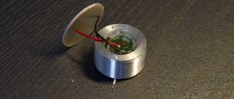
The laser module itself was one of the first to be purchased. Power 2W, since this was the best option for reasonable money.
Here is the laser module itself.
And so, it was decided that the X axis would travel along the Y axis and its design began. It all started with the carriage... The entire frame of the machine was made from aluminum profiles of various shapes, purchased in Leroy.
At this stage, sketches no longer appeared on notebook paper; everything was drawn and invented in the Compass.
Having bought 2 meters of a square profile 40x40 mm to build the frame of the machine, in the end only the carriage itself was made from it..))
Motors, linear bearings, belts, shafts and all electronics were ordered from Aliexpress during the development process and plans for how the motors would be mounted and what the control board would be changed along the way.
After a few days of drawing in Compass, a more or less clear version of the machine design was determined.
And so the X axis was born..))
Sidewalls of the Y axis (sorry for the photo quality).
Fitting.
And finally the first launch!
A simple 3D model of the general appearance of the machine was built in order to accurately determine its appearance and dimensions.
And off we go... Plexiglas... Painting, wiring and other little things.
And finally, when everything was adjusted and the last part was painted black, the finish line came!
Now some beautiful photos))
Sometimes you need to sign a gift beautifully, but it’s not clear how to do it. The paint spreads and wears off quickly, so a marker is not an option. Engraving is best suited for this. You don’t even have to spend money on it, since anyone who knows how to solder can make a laser engraver from a printer with their own hands.
Preparation for operation: setup and calibration
At the finish line, it’s worth checking everything again, as well as doing initial calibration and adjustment:
- Check the movement of all carriages. Lubricate the shafts with silicone oil.
- Check the wiring to make sure nothing is shorting or shorting.
- Calibrate the print bed using a blank A4 sheet of paper. Loosen the adjusting screws, place a sheet of paper between the extruder nozzle and the surface itself. Set the correct table geometry and nozzle height, tighten the screws.
- Try to run the test cube so that all the inaccuracies and printing defects come out.
- Download or create the model you want to print. Upload it to the slicer. Set the necessary parameters and transfer the project to the SD card.
- Load the filament into the extruder. The spool of plastic should rotate freely over the printer structure.
- Insert the USB flash drive into the printer and try to print it.
However, this is not all that needs to be considered when installing a printer. Users often make a number of trivial mistakes that can be avoided even before assembly.
Design and principle of operation
The main element of the engraver is a semiconductor laser. It emits a focused and very bright beam of light that burns through the material being processed. By adjusting the radiation power, you can change the depth and speed of burning.
The laser diode is based on a semiconductor crystal, on top and bottom of which there are P and N regions. Electrodes are connected to them, through which current is supplied. Between these regions there is a P-N junction.
Compared to a regular laser diode, it looks like a giant: its crystal can be examined in detail with the naked eye.
The values can be deciphered as follows:
- P (positive) area.
- P - N junction.
- N (negative) area.
The ends of the crystal are polished to perfection, so it works as an optical resonator. Electrons, flowing from a positively charged region to a negative one, excite photons in the P-N junction. Reflecting from the walls of the crystal, each photon generates two similar ones, which, in turn, also divide, and so on ad infinitum. The chain reaction occurring in a semiconductor laser crystal is called the pumping process. The more energy supplied to the crystal, the more it is pumped into the laser beam. In theory, you can saturate it indefinitely, but in practice everything is different.
During operation, the diode heats up and must be cooled. If you constantly increase the power supplied to the crystal, sooner or later there will come a time when the cooling system can no longer cope with heat removal and the diode will burn out.
The power of laser diodes usually does not exceed 50 Watts. Above this value, it becomes difficult to make an effective cooling system, so high-power diodes are extremely expensive to produce.
There are semiconductor lasers with 10 or more kilowatts, but they are all composite. Their optical resonator is pumped by low-power diodes, the number of which can reach several hundred.
Compound lasers are not used in engravers because their power is too high.
Creating a laser engraver
For simple work, such as burning patterns on wood, complex and expensive devices are not needed. A homemade laser engraver powered by a battery will be sufficient.
Before making an engraver
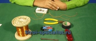
, you need to prepare the following parts for its assembly:
Remove the write head from the DVD drive.
Carefully remove the focusing lens and disassemble the head housing until you see 2 lasers hidden in heat-distributing casings.
One of them is infrared, for reading information from the disk. The second one, red, is the one who writes. In order to distinguish them, apply a voltage of 3 volts to their terminals.
Pinout:
Be sure to wear dark glasses before testing. Never test the laser by looking at the diode window. You only need to look at the reflection of the beam.
You need to select the laser that lights up. You can throw away the rest if you don’t know where to use it. To protect against static, solder all leads of the diode together and set it aside. Saw off a 15 cm section from the profile. Drill a hole in it for the clock button. Make cutouts in the box for the profile, charging socket and switch.
The schematic diagram of a DIY DVD laser engraver looks like this:
Tin the contact pads on the charge control board and holder:
Using wires to pins B+ and B- of the charge controller, solder the battery compartment. Contacts + and - go to the socket, the remaining 2 go to the laser diode. First, solder the laser power supply circuit by surface mounting and insulate it well with tape.
Make sure that the terminals of the radio components do not short circuit with each other. Solder a laser diode and a button to the power supply circuit. Place the assembled device in the profile and glue the laser with heat-conducting glue. Secure the remaining parts with double-sided tape. Reinstall the tact button.
Insert the profile into the box, bring out the wires and secure it with hot glue. Solder the switch and install it. Do the same procedure with the charging socket. Using a hot glue gun, glue the battery compartment and charge controller into place. Insert the battery into the holder and close the box with the lid.
Before using it, you need to set up the laser. To do this, place a sheet of paper 10 centimeters from it, which will be a target for the laser beam. Place the focusing lens in front of the diode. By moving it further and closer, achieve a burn through the target. Glue the lens to the profile in the place where the greatest effect was achieved.
The assembled engraver is perfect for small jobs and entertainment purposes such as lighting matches and burning balloons.
Remember that the engraver is not a toy and should not be given to children. The laser beam causes irreversible consequences if it comes into contact with the eyes, so keep the device out of the reach of children.
CNC device manufacturing
For large volumes of work, a conventional engraver will not cope with the load. If you are going to use it frequently and a lot, you will need a CNC device.
Assembling the interior
You can even make a laser engraver at home. To do this, you need to remove the stepper motors and guides from the printer. They will drive the laser.
The complete list of required parts is as follows:
Connection diagram for all components:
View from above:
Explanation of symbols:
- Semiconductor laser with heatsink.
- Carriage.
- X-axis guides.
- Pressure rollers.
- Stepper motor.
- Drive gear.
- Toothed belt.
- Guide fastenings.
- Gears.
- Stepper motors.
- Sheet metal base.
- Y axis guides.
- X-axis carriages.
- Toothed belts.
- Mounting supports.
- Limit switches.
Measure the length of the guides and divide them into two groups. The first will contain 4 short ones, the second - 2 long ones. Guides from the same group must be the same length.
Add 10 centimeters to the length of each group of guides and cut the base to the resulting dimensions. Bend U-shaped supports for fastenings from scraps and weld them to the base. Mark and drill holes for the bolts.
Drill a hole in the radiator and glue the laser in there using heat-conducting glue. Solder the wires and transistor to it. Bolt the radiator to the carriage.
Install the guide rail mounts onto the two supports and secure them with bolts. Insert the Y-axis guides into the mounts, put the X-axis carriages on their free ends. Insert the remaining guides with the laser head installed on them. Place the fasteners on the Y-axis guides and screw them to the supports.
Drill holes in the places where the electric motors and gear axles are mounted. Reinstall the stepper motors and place the drive gears on their shafts. Insert pre-cut axles from a metal rod into the holes and secure them with epoxy glue. After it hardens, place the gears and pressure rollers with bearings inserted into them onto the axles.
Install the timing belts as shown in the diagram. Pull them tight before fastening. Check the mobility of the X-axis and laser head. They should move with little effort, rotating all the rollers and gears through the belts.
Connect wires to the laser, motors and end switches and tie them together with zip ties. Place the resulting bundles in movable cable channels and secure them to the carriages.
Lead the ends of the wires out.
List of materials
The list of materials needed to create a printer is quite extensive.
Electronics:
- Arduino Mega 2560 series board;
- 1 shield for Arduino Ramps 1.4 (connection between the board and the printer);
- 4 drivers for stepper motors model A4988;
- 4 stepper motors model 28BYJ-48 and 1 motor model Nema 17 (devices that ensure movement of the printing element across the field);
- 3 optical limit sensors (devices for monitoring the dimensions of an object);
- 1 extruder model E3D V5 or V6 (device for pressing heated plastic).
The body part is built from MDF boards and guides.
| Material | Type | Quantity, pcs. |
| MDF boards | 30x40 cm | 1 |
| 6x4 cm | 2 | |
| 34x6 cm | 1 | |
| 15x4 cm | 1 | |
| Bearings | Linear in a round housing LM8UU | 12 |
| Pulleys | GT2 | 2 |
| MK8 | 1 | |
| Toothed belt | GT2 | 1 |
| A tube | PTFE | 1 |
| Guide rods | Length - 22 cm | 2 |
| Length - 17.5 cm (diameter - 8 mm) | 4 | |
| Shaft | M5 thread | 1 |
| Hex nuts | M5 | 2 |
| M4 | 20 | |
| M3 | 10 | |
| Screws | M3×16 mm | 8 |
| M3×25 mm | 6 | |
| M4×45 mm | 4 | |
| M4×60 mm | 2 | |
| M4×20 mm | 4 | |
| Screws | Little ones | 12 |
To assemble a 3D printer, you also need to make fastening parts.
All components are needed in reserve, because mistakes when constructing such structures are difficult to avoid.
The cost of components (electronic and mechanical) is 4,000 rubles. It can be reduced by using cheaper elements and materials:
- instead of MDF boards, use laminated chipboard products;
- instead of the Mega model, buy an Arduino Uno;
- Instead of original Arduino boards, purchase Chinese analogues from AliExpress, which have the same characteristics and the same pinout (this needs to be monitored additionally).