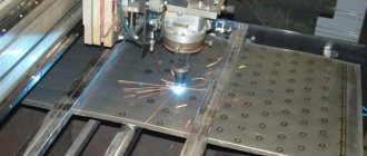
Semi-automatic welding is used in many industries, as well as in everyday life. This is a simple and effective way to join metal surfaces using semi-automatic equipment.
In various sources, this method is called differently: mig, mag welding, sometimes even written as mig mag. The correct name is a method mechanized in a protective gas environment with a consumable electrode.
Depending on the protective gas, this method is called mig if an inert gas is used for the protective atmosphere, or mag if the gas is active. Carbon dioxide CO2 is often used as the active gas.
When welding metal surfaces semi-automatically, the wire is fed to the joining point of the parts automatically using a feed mechanism.
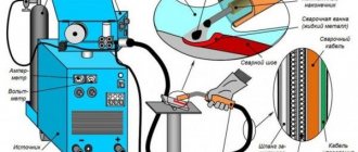
Together with the wire, shielding gas is supplied to the welding zone through a nozzle located on the torch of the semi-automatic welding machine. The gas protects the molten metal of the wire and products from atmospheric gases. The weld is formed by melting both the metal of the welding wire and the metal of the product and mixing them in the weld pool.
Metal transfer.
Melting metal can be transferred either by droplet or jet. Drip is divided into large-drop and small-drop.
The latter, in turn, is more preferable since it minimizes metal spattering. This will depend on the welding machine, the filler wire used, as well as the protective gas environment. All other manipulations, as in the case of welding with a stick electrode, are performed by the master manually.
The electrode is a wire made of aluminum, copper alloy, or steel. Using this method, you can do many operations, for example, perform car body repairs, connect parts made of aluminum, ferrous metal, non-ferrous alloys, repair jewelry, etc.
Setting up the semi-automatic machine before starting work.
In order to weld correctly, beginners working with semi-automatic or as it is also called mechanized welding must do the following:
- Before starting to operate the semi-automatic machine, it is necessary to adjust the voltage and welding current according to the factory instructions. The semi-automatic welding kit includes instructions that describe in detail how this value is selected.
- Setting up the feed mechanism. The instructions say at what speed it is necessary to feed the electrode wire to the welding site for a specific case. The feed speed is adjusted using the handle. When there are no instructions, the semi-automatic machine can be adjusted according to the average values given in the table below.
Basic parameters of the mode for semi-automatic steel welding
After setting up the semi-automatic machine, you need to check how it works, whether the calculation of the modes for semi-automatic welding has been carried out correctly. Checking is carried out on test workpieces.
It will not be possible to set up a semi-automatic machine for welding without welding test parts, since the welding conditions are different. Also, each welder welds differently, some quickly at high current, others slowly. Test seams are inspected for welding defects, bead size, and penetration depth. If something does not meet regulatory standards, then you can change the parameters and make adjustments.
If the semi-automatic welding machine is configured correctly, the seam will be strong and even. The device produces a stable arc, the process proceeds without crackling or splashing.
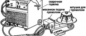
Wire feeder
A wire feeder for a semi-automatic machine can be purchased at almost every electrical equipment store. But it can also be produced independently from available materials. For these purposes, experts recommend finding motors from car wipers, a pair of suitable plates, bearings and a roller with a diameter of 2.5 cm, which must be installed on the motor shaft. Bearings are in turn installed on the plates. The resulting structure is pressed against the roller using a spring.
Diagram of a wire feed regulator for a semi-automatic welding machine
The wire wound on the roller is pulled between the bearing and the roller. All components are mounted on a plate, the thickness of which should not be less than 1 cm, made of durable plastic. The wire outlet must coincide with the attachment point of the supply hose.
Basic mistakes when setting up.
If, when welding, there are splashes and a loud crackling sound from the arc, then most likely you do not have enough welding current. It is necessary to add amperage and increase the wire feed speed.
On most welding machines, the current setting is combined with the wire feed speed setting. But there is also a separate setting.
If the welding process produces sagging. There is a lot of molten metal or the welding bead is wide. If such metal is welded, it burns out, then it is necessary to reduce the voltage or increase the welding speed. Run the burner faster.
In general, the voltage setting affects the depth and width of the weld. If the voltage is high, spatter appears and the seam width increases. The penetration depth decreases.
Also, after completing the welding process, look to see if there are any pores on the seam. If there is, you most likely have low gas supply. This will also be noticeable during welding as the process will be unstable. Metal splashes can also be caused by a lack of gas protection.
In general, gas consumption depends on how quickly the welding proceeds and where it occurs. Because on the street, where there is wind or in a drafty room, the protective gas blows away. This makes the welding process unstable, as already mentioned, and the result will be unsatisfactory.
Semi-automatic setup diagram
- We set the parameters from the creek or from the table from the website
- Let's start cooking the stock
- If the metal transfer is large and splashes fly, then add feed speed and voltage.
- If the metal is burned through or the wire sticks into the bottom of the bath, reduce the feed speed.
- We are looking for the best option. You can see what it looks like in the video at the end of the article.
Before welding, metal surfaces must be prepared. Using special tools and substances, the metal is cleaned and degreased. The diameter of the welding wire must be carefully selected to match the thickness of the parts being welded. The brand must be selected based on the material to be boiled. Otherwise we will get a marriage. As a rule, wire from 1.0 to 2.4 mm is used. We connect the ground cable to the welding machine.
Inductance.
Inductance is a useful setting in a semi-automatic welding machine. On a semi-automatic welding machine, if there is an adjustable inductance value, it must be used correctly so that it improves the welding process. It ensures a smoother welding process by controlling metal transfer. We adjust the inductance based on the recommended values.
You need to know that the inductance needs to be increased as the current increases. Because at low currents up to 140A, metal transfer occurs in small droplets and an increase in inductance will only disrupt the process. The seam will be rough and there will be a lot of splashes. In modes up to 140-160, the inductance should be minimal.
As the current increases, it is necessary to add inductance for smoother weld formation. In general, the presence of inductance adjustment in a semiautomatic device noticeably improves the process and reduces the amount of splashes.
Gases. Inert, active, mixtures.
Most often, a semi-automatic device with gas protection is used in the form of inert (argon, helium), active (CO2) or mixtures of gases in various ratios. The most commonly used mixtures are a mixture of Ar and CO2 in a ratio of 5-15% and 85-95%, respectively.
When using this mixture, fine-droplet and jet transfer of metal becomes possible. The process proceeds smoothly due to stable arc burning. Another gas mixture often used in industry is helium argon in a ratio of 25-30% Ar and 70-75% He. Adding helium will increase the arc temperature and make welding thick metal much easier.
This mixture provides very high levels of protection resulting in a minimum of weld defects. To reduce the cost of welding work, a mixture of helium and argon is also used in a one-to-one ratio. This mixture is universal for thin and thick products, ensuring high quality.
Cored wire.
Semi-automatic welding in some cases is carried out without gas protection, but using flux-cored wire. These methods are rarely used due to the high cost of cored wire, and working with flux limits the scope of application of this method in ceiling and vertical positions.
Which is not applicable in installation conditions. Their obvious advantage is the ability to weld in the wind, since the gas protection is blown away and this leads to welding defects in the form of pores, lack of fusion and craters.
Device for measuring the speed of electrode wire movement
DESCRIPTION 04 INVENTIONS TO AUTO-IZUM SVI IZLSTRUTU Union of Soviet Socialist Republics (61) Additional to the author.
seid-vu(22) Declared 04/04/80 (21) 2905004/25-27 R 1)M. CL V 23 K 9/12 with the addition of the application M - State Committee of the USSR and the grandfathers of inventions and discoveries (54) DEVICE FOR MEASURING THE SPEED OF MOVEMENT OF ELECTRODE WIRE The invention relates to mechanical engineering, in particular to the production of devices for measuring the speed of movement of electronic wire in automatic welding machines. It is known a device for measuring movement speed, containing a measuring unit in the form of a drum with a roller, a wire transducer and an indicator of the measured value 111 The disadvantage of this device is that it operates in stationary conditions. This device cannot measure the absolute speed of movement, but can only monitor deviations from a given speed using a drum, which is rotated relative to the axis by an angle proportional to the geometric sum of the constant speed of rotation of the bar O ban and the speed of movement of the controlled element. A device for measuring foundry speeds is known, containing a drive contact roller located in the housing, installed on the input shaft of the gearbox and a measuring device 21. A disadvantage of the known device is that the contact roller is pressed against the welding wire manually, and it is impossible to ensure constant pressure manually. Changing the pressing force negatively affects the accuracy of measuring the speed of movement. In addition, the measurement of smear speeds is impossible, since the lower limit of the linear speed measured by it is 600 m/h, and the maximum speed of movement of the welding wire with a consumable electrode does not exceed 70 m/h. Therefore, to use this device for measuring wire feed speed , it is necessary to remake the gearbox of this device in such a way that its gear ratio increases 10 times, which means the preload force will accordingly increase 10 times. If the contact roller is pressed against the wire with such force, then the movement of the wire may stop and the speed cannot be measured. The purpose of the invention is to ensure the measurement of low speeds and increase the stability of the measurement, as well as automate the measurement process. This goal is achieved by the fact that the device for measuring the speed of movement electrode wire, 884904, containing a drive contact roller located in the housing, installed on the input shaft of the gearbox and a measuring device, equipped with an L-shaped rod installed with the possibility of Fixation in the housing and a double-armed lever spring-loaded from it, hinged in the housing and interacting with one arm with the measuring device , a cam made in cross-section in the form of an equilateral triangle, installed on the output shaft of the gearbox and interacting with the other arm of the lever, a pressure roller mounted on one end of the L-shaped rod. The device is also equipped with two cams with protrusions, the number ratio of which is 2, installed on one axis in the housing with the possibility of interaction of a cam with a large number of projections with a cam mounted on the output shaft of the gearbox, and a cam with a smaller number of projections with the free end of the L-shaped rod. In Fig. 1 shows the device, general view; in Fig. 2 - section L-L in Fig. 1. The device consists of a housing 1 in which a reduction gear 2 is installed, on the input shaft of which a drive contact roller 3 is installed, a cam 4 is rigidly mounted on the output shaft of the gearbox 2, connected to a swinging lever 5 having two arms 6 and 7. In the housing 1, a stopwatch 8 and an L-shaped rod 9 are installed, at one end of which a pressure roller 10 is hinged. The L-shaped rod 9 is spring-loaded relative to the body 1 by a spring 11 and is fixed by a ball 12. In addition, two cams 13 and are hingedly mounted in the body 1. 14. Wire 15 is inserted between rollers .3 and 10, and on the housing cover. 1 usta-. The calibrated scale from Fig. has been updated. kaya in two rows. The marks located in one row indicate seconds, and the marks in the other row indicate speed - meters per hour. The device works as follows.. The device is brought to the moving wire 15 and pressed on the L-shaped rod 9. In this case, the roller 10 p draws wire 15 to contact roller 3, and the L-shaped rod 9 is fixed by ball 12. Roller 3 rotates under the action of wire 15 and through gearbox 2 turns cam 4, the protrusion of which presses the arm.b of lever 5, while arm 7 of this lever 5 turns on the stopwatch 8. At the same time, cam 4 turns cam 13 with one of its protrusions so that its protrusion is installed opposite the rod 9. Time counting begins. Cam 4 continues to rotate and when its next protrusion comes into contact with arm b of lever 5, the stopwatch 8 is turned off. At the same time, the other protrusion of cam 4 rotates cam 13 together with cam 14 in such a way that the protrusion of cam 14 interacts with rod 9 and is removed from a fixed position. Under the action of spring 11, roller 10 comes out of contact with wire 15 and the device stops working. The speed is assessed on a scale where 1 e against the number of seconds during which the measurement took place, the value of the wire feed speed of 1 m/h is read. The use of the proposed device will make it possible to measure low speeds of movement of the welding wire by cutting off the time interval between two consecutive switching on of the measuring device and will increase convenience measurements due to the fact that the contact roller is not pressed against the wire manually, but is clamped during the welding process between the contact and pad rollers automatically with a constant force. Formula of invention 1. device for measuring the speed of movement of the electrode wire, containing a drive contact roller located in the housing, mounted on the input shaft of the gearbox and a measuring device, differing in that, in order to ensure the measurement of low speeds and increase the stability of measurements, the device is equipped with an L-shaped rod installed with the possibility of fixation in the housing and a lever spring-loaded from it, hinged in the housing and interacting with one arm with a measuring device, a cam made in cross-section in the form of an equilateral triangle, mounted on the output shaft of the gearbox and interacting with the other arm of the lever, a pressure roller mounted at one end G -shaped rod.52.device according to claim 1, with the exception that, in order to automate the measurement process, the device is equipped with two cams with a height of 2, the ratio of which is 2, installed on one axis in the housing with the possibility of interaction of the cam with a large number of protrusions, the cam mounted on the output shaft of the gearbox, and the cam with a smaller one884904 1. Author's certificate of the USSR B 302 bbb, class, 6 01 R 3/18, 1970.2. Clock tachometer T 410-R,I., 197 b (prototype). Fbr. Rel E, Guzikov3 Fanta Corrector I. Demin eakaz 1 yu81/1 b Circulation 1151VNIIPI State Committee for Inventions. and opened13035, Moscow, Zh, Raushskaya NabPPP Patent", Uzhgorod, st. Design, 4 number of protrusions - with the free end of an L-shaped rod. Sources of information taken into account during the examination Composition Editor A. Vlasenko Technical See
Features of semi-automatic welding
The advantages of semi-automatic welding are obvious:
- A very simple way. You can learn how to cook high-quality compounds very quickly. It will be easy for beginners to master.
- The speed of joining metal surfaces is much higher than when using conventional manual electrode welding.
- During the process, it is possible to observe the weld pool and the process of formation and crystallization of the seam. Which in turn improves the quality of the resulting product due to timely detection of defects and adjustments to the process itself.
- The weld is of excellent quality. The fine flake nature of the compound ensures high ductility.
- There is also a high degree of automation, and this increases overall productivity.
- Mechanized welding can be carried out both in the lower position and vertical and ceiling without restrictions.
- Not much heating of the product and, as a result, the ability to process thin products and reduce metal deformation.
- The connection point does not require cleaning.
- The cost of performing the process using semi-automatic equipment is lower than with other welding methods.
- Semi-automatic welding allows you to connect galvanized surfaces without damaging the coating.
The disadvantages include:
That when welding parts with a semi-automatic machine, the level of arc radiation is stronger than when using other methods.
Also during operation there is a strong splashing of metal. This leads to significant losses of electrode wire, as well as the need for stripping. Which gas is best for semi-automatic welding? In the vast majority of situations, carbon dioxide is used for welding.
Helium and argon are also suitable. These gases are used both in pure form and in mixtures. The semi-automatic machine is supplied with direct current with a reverse polarity connection: plus is supplied to the wire, minus is supplied to the workpiece.
Winding up a welding transformer
We take the OSM-1 transformer (1 kW), disassemble it, put the iron aside, having previously marked it. We make a new coil frame from PCB 2 mm thick (the original frame is too weak). Cheek size 147×106mm. Size of other parts: 2 pcs. 130×70mm and 2 pcs. 87x89mm. We cut out a window measuring 87x51.5 mm in the cheeks. The coil frame is ready. We are looking for a winding wire with a diameter of 1.8 mm, preferably in reinforced fiberglass insulation. I took such a wire from the stator coils of a diesel generator). You can also use ordinary enamel wire such as PETV, PEV, etc.
Fiberglass - in my opinion, the best insulation is obtained. We begin winding - primary. The primary contains 164 + 15 + 15 + 15 + 15 turns. Between the layers we make insulation from thin fiberglass. Lay the wire as tightly as possible, otherwise it won’t fit, but I usually didn’t have any problems with this. I took fiberglass from the remains of the same diesel generator. That's it, the primary is ready.
We continue to wind - secondary. We take an aluminum busbar in glass insulation measuring 2.8x4.75 mm (can be purchased from wrappers). You need about 8 m, but it is better to have a small margin. We begin to wind, laying it as tightly as possible, we wind 19 turns, then we make a loop for the M6 bolt, and again 19 turns. We make the beginnings and ends 30 cm each, for further installation. Here is a small digression, personally, for me to weld large parts at such a voltage, the current was not enough; during operation, I rewound the secondary winding, adding 3 turns per arm, in total I got 22+22. The winding fits snugly, so if you wind it carefully, everything should work out. If you use an enamel wire as a primary material, then you must impregnate it with varnish; I kept the coil in the varnish for 6 hours.
Semi-automatic welding machine. What it is?
This is a special device for welding with a molten electrode. The electrode is a welding wire fed automatically.
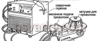
The main design elements of a semi-automatic welding machine:
- Source of electric current;
- Wire reel;
- Burner. It is also sometimes called derak;
- Electrical cables for connecting the semiautomatic device to the electrical network;
- Welding mass cable with clamp;
- Sleeve connecting to a container filled with gas;
- Control and control mechanisms for equipment control.
- A mechanism that feeds the electrode wire to the welding site.
During welding, a cylinder filled with gas under pressure is used.
The electrode wire, supplied in coils and installed in the device, is fed automatically by a special feeding mechanism included in the device.
The choice of speed for welding surfaces, voltage for a semi-automatic machine, and moving the electrode wire at the joining site is done manually.
What types of semi-automatic welding machines are there?
This type of equipment comes in different types. There are layout, single-body, double-body models.
Based on the method of movement at the junction of parts, semi-automatic machines are divided into stationary and mobile.
Based on the method of connecting equipment to the power source, semi-automatic devices are divided into single-phase and three-phase.
Depending on the type of material used:
- Used for joining parts under a flux layer. Rarely used.
- Used for work in a protective gas environment. Used extremely often.
- Devices that perform welding using flux-cored wire. In this case, the seam is also protected by gases. Kemppi welding machines have become very popular. Sometimes this type is even called camping welding or camping.
According to the feeding method, semi-automatic devices are divided into three types - pull, pull-push, and pushing devices.
Do-it-yourself semi-automatic welding machine - diagrams and description
In this article we will tell you how to make a semi-automatic welding machine with your own hands? The main thing that is needed for this is enthusiasm. After reading the theoretical information, you can begin assembly. To begin with, I would like to clarify what is the difference between a semi-automatic welding machine and a machine that works with electrodes.
When manual welding is carried out, the load current must be constant, but in automatic welding the main thing is voltage stability. This is, in general terms. We will manufacture a universal device, i.e. automatic with arc welding (MAG/MMA).
How to properly perform semi-automatic welding.
Let's check if everything is ready.
We check the size of the welding wire overhang. If the wire end sticks out too much, the tip can be trimmed with a special tool. It is important to monitor the sharpness of the tip of the electrode wire. The pointed end ignites faster and easier. Before each work cycle and suture, the wire is bitten off. This makes it easier to get started.
We check whether shielding gas is supplied when the button is pressed. If welding is carried out in the cold season, then it is necessary to use gas heating. For this, a special heating device is used.
Arc ignition.
We light the arc. To do this, you need to touch the end of the welding wire to the workpiece in the lower corner of the edges, press the button located on the torch body.
Immediately after startup, two processes occur simultaneously - gas and electrode wire are supplied to the process zone. During the welding process, the torch must be held in such a way that it is possible to control the weld pool. This will ensure the correct location of the weld seam.
Main stage.
During operation, it is necessary to control the sound of the welding arc. A loud crackling sound indicates that the welding wire feed speed is incorrectly set. In this case, it is necessary to either increase the feed speed.
It is important to monitor the geometry of the resulting weld joint. If little penetration of the base metal is obtained, and the bead is narrow, it is necessary to increase the welding current voltage. Welding is performed with a ignited arc.
During operation, it is necessary to guide the burner not only along the joint, but also to move it, making oscillatory horizontal movements shown in the figure. This can improve the structure of the weld seam, significantly reducing the structure of the welded joint.
I – welding the root pass, II – filling the edges (second layer), III – filling and facing the seam (3 and subsequent layers)
It is imperative to protect the body from metal splashes.
To stop the welding process, you just need to stop pressing the button and remove the torch from the place where metal surfaces are welded.
Welder diagram and details
Due to the fact that the semi-automatic circuit was analyzed from such devices as PDG-125, PDG-160, PDG-201 and MIG-180, the circuit diagram differs from the circuit board, since the circuit emerged on the fly during the assembly process. Therefore, it is better to stick to the wiring diagram. On the printed circuit board, all points and parts are marked (open in Sprint and hover your mouse).
Signet, see drawing in the archive
A single-phase 16A type AE circuit breaker is used as a power and protection switch. SA1 - welding mode switch type PKU-3-12-2037 with 5 positions.
Resistors R3, R4 are PEV-25, but they don’t have to be installed (I don’t have them). They are designed to quickly discharge choke capacitors.
Now for capacitor C7. Paired with a choke, it ensures combustion stabilization and arc maintenance. Its minimum capacity should be at least 20,000 microfarads, optimal 30,000 microfarads. Several types of capacitors with smaller dimensions and higher capacity were tried, for example CapXon, Misuda, but they did not prove to be reliable and burned out.
As a result, Soviet capacitors were used, which still work to this day, K50-18 at 10,000 uF x 50V, three in parallel.
Power thyristors for 200A are taken with a good margin. You can install it at 160 A, but they will work at the limit, and you will need to use good radiators and fans. The used B200s stand on a small aluminum plate.
Relay K1 type RP21 for 24V, variable resistor R10 wirewound type PPB.
When you press the SB1 button on the burner, voltage is supplied to the control circuit. Relay K1 is activated, thereby, through contacts K1-1, voltage is supplied to the electromagnetic valve EM1 for acid supply, and K1-2 - to the power supply circuit of the wire drawing motor, and K1-3 - to open the power thyristors.
Switch SA1 sets the operating voltage in the range from 19 to 26 Volts (taking into account the addition of 3 turns per arm up to 30 Volts). Resistor R10 regulates the supply of welding wire and changes the welding current from 30A to 160A.
When setting up, resistor R12 is selected in such a way that when R10 is turned to minimum speed, the engine still continues to rotate and does not stand still.
When you release the SB1 button on the torch, the relay releases, the motor stops and the thyristors close, the solenoid valve, due to the charge of capacitor C2, still remains open, supplying acid to the welding zone.
When the thyristors are closed, the arc voltage disappears, but due to the inductor and capacitors C7, the voltage is removed smoothly, preventing the welding wire from sticking in the welding zone.
Positions and differences of semi-automatic welding seams
In order to quickly master semi-automatic welding, you need to understand the positions in which the process has to be carried out.
The positions of the welding seams in space are different. They are divided into seams, which are performed by the welder in the lower position, hence the name - lower. Cooking in this position can be done both from right to left and from left to right. You can use the technique of applying narrow rolls or cook with transverse oscillatory movements.
Vertical position.
The next position is vertical. It is more convenient to make welding seams downhill when the torch is positioned at an angle to the bottom. This ensures that the metal of the weld pool is kept from flowing out due to the pressure of the welding arc.
This method is good for thin metal when deep penetration is not required. In cases where this is required, the lift welding method is used. It is performed at an inclination angle of the weld ranging from 60 to 120 degrees.
Ceiling position.
More than 120 to 180 degrees is the so-called ceiling position of the weld. It is the most difficult to perform. Since the metal of the weld pool flows out, creating a defect in the form of an overflow, and the process is carried out in an extremely inconvenient position almost above the welder’s head. To weld it, place the torch perpendicular to the product or tilted backwards. It is also necessary to make oscillatory movements with the torch during the welding process.
Horizontal position.
Let's consider another position of the welding seam - horizontal. Its implementation is more difficult than the lower one due to the same leakage of metal. When welding horizontal seams, it is most convenient to oscillate the transverse torch starting from the bottom of the edges of the product.
Horizontal seams must be made with oscillations of the burner, starting to cook from the scorching edges.
To make vertical seams of thin sheets, the downhill welding method (from top to bottom) is used, since using the uphill method results in a large input of heat, which negatively affects the structure through burns and deformation. Electrode tilt 20-35º
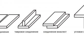
There are many types of welded joints. For mechanized welding they are determined by GOST 14771-76. According to which the types of seams are determined: butt, lap, corner, tee. Used both for welding pipes and profile structures, and for sheet structures.
This is what the main butt joints C4, C5, C7 and C18 look like
This is what the main butt joints C4, C5, C7 and C18 look like
Fillet weld U1
Knowledge of what semi-automatic welding machines are and how to use them allows you to join metals as efficiently and efficiently as possible.
The burner can be controlled with one or two hands. In the second case, the welding seam will be much smoother and of better quality, because the welder works more confidently and holds the device in his hand more firmly.
One hand clasps the burner so that the index finger can rest on the start button. The other hand is placed on top of the leading hand, directing and controlling the movements of the first.
How to weld aluminum parts using a semi-automatic welding machine?
When connecting aluminum surfaces, it is necessary to use aluminum wire. Plastic wire can easily stick inside the burner and bend in different directions. This can be avoided by using special current collectors.
High-quality argon is used to protect the connection point. Choose the right pressure. It should protect the weld pool from air suction.
This phenomenon occurs when shielding gas is supplied too quickly. It is necessary to correctly adjust the inductance on the semi-automatic welding machine.
When welding, the welder needs to break through the film that covers the aluminum, pull the arc at a certain speed, and monitor the weld pool. This is the only way to achieve an even, durable seam.
Carbon dioxide welding
CO2 is one of the most inexpensive gases. Welding metal semi-automatically in carbon dioxide is a common type of welding.
Suitable for joining non-ferrous and ferrous metals, including thin workpieces. A narrow edge is sufficient to connect the parts.
The wire melts very quickly, which reduces the welding period by several times. The result is a seam of excellent quality.
The semi-automatic machine qualitatively connects metal surfaces of different thicknesses.