8.2. Increasing the mass and rigidity of foundations when strengthening them (Part 9)
During the operation of centrifugal smoke exhausters in the recirculation of gases of the GD-26×2 brand to turbine units with a capacity of 800 thousand kW, increased vibrations of the bearings of the smoke exhausters and the bearings of their engines arose.
As a result, bearing failures occurred. In addition, vertical cracks with an opening width of 0.3-2 mm appeared in the body of the foundations of the smoke exhausters, which ran from the upper edge of the foundation to the ground surface and were located in the places where the machine was attached to the foundation (Fig. 8.12, a). The reinforced concrete massive foundations of smoke exhausters are made in the form of a single monolithic block with the necessary ledges and recesses. The upper part of the foundations was significantly weakened by the wells of anchor bolts, while the distance from the edge of the wells to the edge of the foundations in the places where bearings and smoke exhausters were attached was less than required. The measurement results and the obtained vibration modes (Fig. 8.12, b) of the examined smoke exhauster foundations showed that the upper part of the foundations is not a single massif, but is divided into separate conglomerates by through cracks.
The amplitude of horizontal vibrations of the upper edge of the foundation reached 0.07 mm, and the amplitude of the frame and bearing of the smoke exhauster - 0.25 mm, which indicated the absence of a rigid connection between the machine and the foundation. The reasons for this were a decrease in the rigidity of fastening anchor bolts in the foundation body due to the presence of cracks and damage to the integrity of its upper structure, as well as weakening of the tightening of anchor bolts due to the accumulation of plastic deformations in the bolts under the combined action of dynamic loads and high temperatures that arose due to insufficient thermal insulation cars. The latter also contributed to the occurrence of additional temperature deformations in the upper part of the foundation.
The condition of the foundations required immediate strengthening, which was carried out as follows. The upper structure, weakened by recesses and cracks, was reinforced to its entire height with a reinforced concrete belt-cage 0.5 m thick (Fig. 8.12, c, d), which ensured the foundation rigidity required by calculation, as well as a reliable connection between the machine and the foundation due to an increase in the rigidity of the upper part of the foundation in the places where the anchor bolts are attached. Existing cracks were cemented with an expanding cement mortar and filled with epoxy resin where the anchor bolt was installed. To ensure reliable tightening of the fastening nuts, an elastic element was introduced into the anchor bolt tightening unit. At the same time, it was recommended to strengthen the thermal insulation and ensure a gap between its surface and the foundation elements of at least 100 mm. The frame of the cage (class A-II steel, with a diameter of 12 and 8 mm, with a pitch of 200 mm, was connected to the foundation reinforcement by welding using separate rods at the level of the foundation grids. The cage was concreted with concrete grade M 300.
The work examines cases of strengthening individual structural elements of frame prefabricated monolithic foundations of turbine units by increasing the rigidity of these elements operating in the frequency range close to the resonant one. The increase was achieved by increasing the thickness of the concrete sections of the elements (with the addition of reinforcement according to calculation), as well as by introducing additional metal connections.
Strengthening the foundations of impact machines is mostly carried out during reconstruction in connection with the installation of more powerful equipment on the foundations or in case of significant vibrations of buildings. Cases of strengthening such foundations caused by errors in their design or construction are described in the works.
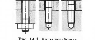
Strengthening the foundations of impact machines (such as forging and stamping hammers, impact piledrivers) is mainly limited to the reconstruction of the hammer part. As an example (data from M.I. Zabylin), let us consider strengthening the foundation of a headframe, the underframe part of which (Fig. 8.13) in the upper part was destroyed during operation into separate conglomerators, and the reinforcing mesh was torn. Before strengthening, the conglomerators were partially removed. In drilled vertical holes with a diameter of 40 mm, reinforcing bars with a diameter of 36 mm of class A-II were installed using epoxy glue to a depth of about 1 m. A reinforcement mesh of concrete made of concrete grade M 300 was attached to these bars to the height of the remote part of the destroyed concrete.
Calculation of the base plate and anchor bolts of an eccentrically compressed column
Home / Design of steel structures / Columns / Column bases / Calculation of the base plate and anchor bolts of an eccentrically compressed column
The shoe of an eccentrically compressed column exerts uneven pressure on the foundation surface. In the direction of the moment, the shoe plate exerts a compressive effect on the foundation, and on the opposite side it tends to break away from the foundation surface.
Scheme for calculating anchor bolts
This separation is prevented by anchor bolts that pinch the column. During design, the width of the base slab B is initially specified. The length of the slab is determined from the condition that the maximum stress in the foundation at the edge of the slab σb max is less than the calculated compressive resistance of concrete:
In this case, the greatest tensile stress at the opposite edge of the slab will be equal to
The most advantageous combination of loads to determine N and M is selected.
By solving equation (37.VIII) for L, you can determine the required length of the slab based on the accepted width of the slab B and the given design resistance of concrete Rb:
After determining the dimensions of the slabs L and B, they proceed to constructing the base and determining the thickness of the slab.
When determining the thickness of the slab, it is assumed (somewhat as a safety margin) that the slab is loaded with a uniformly distributed load q = σb max (since most moments are of different signs). An exception is allowed only for the middle sections of the slab, which can be counted on to have a uniformly distributed load equal to the maximum stress corresponding to the edge of this section.
When calculating anchor bolts, it is assumed that the tensile force Z, determined by the stretched zone of the stress diagram, is completely absorbed by the anchor bolts.
Therefore, composing the equilibrium equation regarding the center of gravity D of the compressed triangular zone; stress diagrams, i.e., points of application of the resultant compression forces, we obtain
Hence the total force Z in all anchor bolts located on one side of the shoe:
and, accordingly, the total cross-sectional area of these anchors (calculated by cutting)
where m is the coefficient of column operating conditions;
mс is the coefficient of operating conditions of anchor bolts, taken equal to 0.65;
Rp is the design tensile strength of anchor bolts, taken equal to 2,100 kg/cm2 for bolts made of steel Art. 3.
The value a is determined from the geometric relation
When determining the value of c, the absolute values of σb are taken (without taking into account their sign).
The shoulder of the anchor bolts, i.e. size y, is determined as follows. First, the part for attaching the anchor to the column shoe is designed and thus the size e is determined. The required size y will be obtained from the equation
When calculating anchor bolts, it is necessary to take a combination of loads that gives a maximum value of M at a minimum N (for example, with wind, but without cranes and snow).
The cross-sectional area of one anchor will obviously be obtained if the total area determined by formula (41.VIII) is divided by the number of anchors located on one side of the shoe. Typically, anchor bolts are placed symmetrically on the other side of the shoe.
The diameter of the anchors is accepted in the range from 20 to 76 mm, since thicker anchor bolts are difficult to manufacture. The anchors can be secured in the foundation by adhesion to the concrete, which determines the depth of their embedding, or by using support washers.
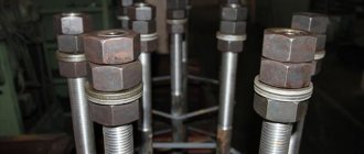
Types of anchors
When determining the length of anchor bolts, you can use the table as a guide. The anchor is usually cut to a length of 120 - 150 mm. When designing the base, it is necessary to ensure that the nut can be freely turned when tightening the bolt. Therefore, it is advisable to take the minimum distance from the bolt axis to the traverse equal to 1.5 d (where d is the diameter of the bolt).
The anchor bolts are placed behind the base plate so that during installation the column can be moved in all directions (approximately 20 mm), installing it along the axis.
Table Normal sizes of anchor bolts.
The height of the traverse is determined by the placement of welds or rivets attaching the column rod to the traverse.
Determination of slab thickness
Determination of the thickness of the slab for the crane run based on the condition of its operation in bending.
Example. It is required to calculate the structure of the lattice column shoe shown in the figure. The maximum design forces in the column are taken to be the same as in the example:
In this example, the greatest forces in the branches in the crane branch were determined to be Np.v = 135.75 t; in the outer branch Nн.в = 113 t.
The design combination of forces in the column for calculating anchor bolts (from constant and wind loads) is accepted:
The calculated resistance to axial compression of concrete grade 100 Rb = 44 kg/cm2. Shoe material St. 3; electrodes type E42. Working conditions coefficient m = 1.
Solution. 1) Determine the required area of the support plates:
under the crane branch
under the outer branch
We assign the dimensions of the slabs:
The pressure on concrete will be equal to:
2) We determine the required thickness of the slab for the crane branch from the condition of its operation in bending. In section 2, the slab acts as a cantilever under a certain load in the form of concrete back pressure q = σb.
Moment in the console
In section 1, the slab is supported on three sides and is also loaded with a uniformly distributed load at the ratio of the sides
We find from the table the coefficient σ3 = 0.128. The maximum bending moment in the middle of the free side is
This moment is greater than the cantilever moment, and therefore we select the thickness of the slab based on it [according to formula (36.VIII)]
We take δpl = 24 mm.
3) We calculate the traverse and base ribs. We take a traverse made of 450 X 12 sheets and the thickness of the seams attaching the branch to the traverse is hsh = 10 mm. Assuming when calculating the seams that the force of the branch is transmitted to the base plate only through the traverse sheets, which are welded to the I-beam with four seams, and taking the estimated length of the seam equal to lsh = 45 - 2 = 43 cm (where 2 cm is a deduction for lack of penetration of the ends of the seams), find the tension in the seams
In the seams attaching the traverse sheets to the slab, with hsh = 10 mm, the stress will be equal to
We check the middle rib that strengthens the slab; this rib with dimensions 350 X 300 X 10 absorbs pressure from concrete σb from a load area with a width of 370:2 = 185 mm.
The load acting on the rib will be equal to:
For an edge that acts as a cantilever pinched into a wall, we find:
Support reaction of console A, shifting the rib relative to the wall:
We calculate the welds attaching the console to the wall. There are two welds hsh = 10 mm. The seam is subjected to shearing force A and moment M. We check according to the conventional formula
Where
4) We calculate the anchor bolts. The required total cross-sectional area of the anchor bolts attaching the outer branch of the column will be determined by the formula (41.VIII):
Here a = 45.2 cm is the distance from the axis of the column to the middle of the base plate of the crane branch;
y - 100 cm - distance from the axis of the calculated anchors to the middle of the same slab;
mс = 0.65 - coefficient of operating conditions of anchor bolts;
Rp - 2,100 kg/cm2 - design tensile strength of anchor bolts.
We determine the values of a and y based not on formulas (42.VIII) and (43.VIII) derived for a solid base plate, but from equilibrium conditions, equating to zero the sum of the moments of all forces relative to the center of the compressed stress diagram.
We divide the found total cross-sectional area of the bolts by 2 (number of bolts):
According to the table, we accept bolts with a diameter of d = 56 mm, the length of whitening into concrete is l3 = 1,000 mm.
“Design of steel structures”, K.K. Mukhanov
Calculation and design of bases
Calculation of the base plate and traverse of a centrally compressed column The dimensions of the base plate of a centrally compressed column are determined by the calculated resistance of the foundation concrete to axial compression R6 (taken equal to 44 kg/cm2 for concrete grade 100). The minimum area of the slab is determined by the formula where N is the design force in the column. Having found the required area of the slab, they proceed to designing the shoe, assigning the width of the slab...
Types of anchor bolts
First of all, anchor fasteners differ in their mode of action. They are:
- Chemical. Such products are a capsule with glue, which is placed in the hole. As soon as the anchor begins to screw into the wall or any other surface, the capsule is crushed and the glue polymerizes, securely fixing the fastener. The chemical anchor bolt for concrete is indispensable for hollow slabs. However, such products are expensive, so they are not so popular. Another disadvantage is that after installing the anchor you will have to wait for some time until the glue “sets”.
- Mechanical. Bolts of this type are attached due to the expansion force when screwing the products into the concrete mass. Fasteners of this type are cheaper and are used much more often.
In turn, a mechanical anchor bolt can be:
Klinov
The wedge anchor (KA) is attached thanks to a special wedge located at the inner end of its sleeve. When hammered, the fastener expands the sleeve, thanks to which the element is securely fixed.
Also on sale are wedge-type anchor bolts with a nut, in which wedging is carried out thanks to a separate rod. After fixing the fastener, it is removed from the hole, and a special pin is installed in its place.
The anchor bolt with nut can be electrogalvanized (KA), acid-resistant (KAN) or hot-dip galvanized (KAK). Fasteners of this type also include a stainless steel screw anchor (RAR).
Hammerable
Driven-in anchors are characterized by a simple design - they do not have a wedge. Fastening is carried out thanks to the special edges of the sleeve, made of softer metal, which are deformed during the process of driving the sleeve.
To secure such an anchor, you do not need to measure the drilling location with millimeter precision; deviations in diameter and depth are also allowed.
This type of anchor is suitable for brickwork, natural stone and monolithic concrete surfaces.
Expandable
An expanding anchor (or “butterfly”) is used for thin-walled and sheet materials. The design of such a fastening element is distinguished by the presence of slots located in the middle of the sleeve. In the process of tightening the screw, its back part begins to move along the thread, and the sleeve is deformed, thereby forming peculiar petals that press the anchor (these elements are very clearly visible in the photo).
The main advantage of the “butterfly” is that the product can be dismantled at any time. To do this, you do not have to perform diamond cutting of concrete and other labor-intensive work.
“Butterfly” is suitable for plasterboard, plastic and fiberboard. If there are metal elements (reinforcement) in the wall, then before installing anchors in concrete, it is necessary to remove the reinforcing particles.
spacer
Expansion anchor bolts for concrete are considered the most popular due to their ease of use. When installing them, it is not necessary to strictly adhere to tolerances, depth and diameter of the hole. This device operates on the principle of collet expansion of the sleeve by screwing a cone-shaped sleeve into it.
There is also a double-expansion anchor for concrete, which contains two moving couplings at once. Thanks to this “structure” the product is characterized by increased fastening strength.
These types of anchors are used only for concrete and solid brick.
In addition, special products equipped with hooks and rings can be found on sale. The anchor loop is very convenient for installing lighting fixtures and communications.
For the production of fastening anchors, stainless steel coated with a layer of anti-corrosion compound is most often used. Products can be of different sizes.
Calculation of the distance from the edge of the foundation to the anchor bolt
Anchor bolts are calculated for static and dynamic loads. The magnitude, direction and nature of the operating loads from the equipment on the bolts must be indicated in the assignment for designing foundations for the equipment.
The steel rating of design bolts operated at design winter outside air temperatures up to minus 65°C inclusive must be assigned in accordance with the instructions in Table. 1.
Note. Bolts may be made from other grades of steel, the mechanical properties of which are not lower than the properties of steel grades indicated in Table. 1.
In all cases, structural bolts may be made from steel grade VSt3kp2 in accordance with GOST 380.
The calculated tensile strength of bolt metal R should be taken according to table. 2
All bolts must be tightened to the pre-tightening value F, which for static loads should be taken equal to: f = 0.75 R, for dynamic loads F = 1.1 R, where P is the design load acting on the bolt.
For building structures (steel columns of buildings, etc.), bolts can be tightened with standard hand tools with maximum force (all the way) on the bolt.
The cross-sectional area of the bolts (by thread) should be determined from the strength condition using the formula:
where ko = 1.35 - for dynamic loads; ko = 1.05 - for static loads.
For removable bolts with anchor plates installed freely in a pipe, the coefficient ko for dynamic loads is taken equal to 1.15.
Under the action of dynamic loads, the cross-section of the bolts, calculated using formula (1), should be checked for endurance using the formula:
where x is the load factor taken according to the table. 3, depending on the bolt design; m is a coefficient taking into account the scale factor, taken according to the table. 4, depending on the bolt diameter; a is a coefficient taking into account the number of loading cycles, taken according to the table. 5.
Table 3 (* The embedment depth for bolts with a diameter of less than 16 mm is given in brackets. * The values of the static load coefficient k are given in brackets.)
When calculating fastenings of building structures, the pre-tightening force and cross-sectional area of the bolts should be determined as for static loads, unless there are special instructions in the project.
Basics of the principle of connecting anchors
Anchor connectors are held inside the foundations due to the influence of various forces - emphasis, gluing, friction, but they arise when the monolith interacts with the connection.
During the spacer of the expanding collet, similar forces arise; the stop is distributed over the bolt, where it is compensated by internal resistance, which contradicts the breaking force.
Bonding eliminates the pressure arising from shear stress at the point of contact between the anchor and the concrete.
The choice of fasteners is carried out based on the expected load on one point. The features of the base are taken into account to find the desired type of fastening. An important factor is the main characteristics of the foundation: type, degree of strength, structure.
The size of the anchor system used is selected based on the physical parameters of the structure being installed. The larger and heavier the structure, the longer and thicker the bolts should be.
Then, the optimal distance between the bolts is calculated, according to the weight, dimensions of the attached structure or technical support.
Recommendations for the correct installation of anchors can be viewed in the following video:
Characteristics of connecting products
Some types of anchors have features that are not typical for this class of products. For example, drive-in anchors are used in many types of structures. However, their main feature is the driven installation technology. Fixing such hardware occurs on the principle of placing a sleeve in the hole and then driving it in with a hammer. Then a bolt is screwed in, which acts as a spacer element. The result is a reliable fastening.
Products used in bolted connections are made from high quality materials. The main criterion for reliable installation is maintaining the minimum distance between bolts. The calculation is performed in a certain order, checking the technical characteristics and capabilities of the bolts.
Source
Machine foundation price
If the machine is large and heavy enough, the cost of construction work will be quite significant. It is best to start building the foundation of the machine immediately after concluding a contract for the supply of the machine, by requesting a foundation drawing from the manufacturer. In this case, as a rule, there are 4-8 months to select an experienced work contractor, agree on an estimate and a contract for the manufacture of the foundation
It is important not to delay the start of work until the machine is manufactured. Otherwise, you will have to postpone the start of installation, commissioning and commissioning for the period of approval, production and hardening of the foundation
As a result, this may result in downtime of expensive equipment.
Types of foundation structures
- Baseless base of slab type, dampening vibration with its mass. Such foundations can be poured into formwork only on the first floor of the workshop. Such a design will cost a significant amount, since the maximum amount of building material is spent on the construction of a solid slab-type base. However, the largest machines and mechanisms are mounted only on such foundations.
- Frame foundation. Basement base-floor, mounted on the second floor and above. Such a foundation dampens vibration, transmitting vibrations to the frame of the workshop itself (through contact with the interfloor ceiling). In essence, it is the same slab, only not poured, but assembled from reinforced concrete products installed on the interfloor floor beams. Such a base can only withstand static loads or vibration with minimal amplitude.
- Wall foundation, developing the idea of a strip foundation. The load-bearing load and vibration in this case are taken by load-bearing walls or internal partitions. As a rule, such foundations are placed under mechanisms located on the second floor of the workshop.
- Frame type bases (with beam grillage). This design withstands high-frequency vibration. Therefore, in most cases, foundations for impact mechanisms have a “frame” design. After all, dampers can be installed in the frame supports to dampen vibration.
How to install
First of all, you should pay attention to the fact that the length of the foundation bolt (and, accordingly, the depth of its embedding in the material) should not exceed the height of the foundation structure itself. If you neglect this requirement, you may encounter the fact that the anchor part of the fastener, which ensures the reliability of its fixation, will not be in the strong foundation material, but in loose and soft soil
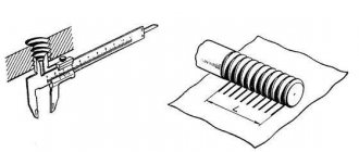
Bolt depth (click to enlarge)
Calculating foundation bolts to determine their holding capacity is another important procedure that must be performed before installing them. Typically, the regulatory document (24379.1-80) does not contain information about such a parameter as the holding capacity of foundation bolts, so you must calculate it yourself.
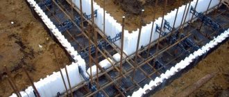
Bolts installed before concreting are temporarily attached to the formwork
into the foundation - this is a simple procedure that can be performed on your own, without involving qualified specialists for these purposes. In order for the result of this procedure to be reliable fastening of anchor bolts in the foundation structure of your future building, you should adhere to the rules for their installation, which are as follows.
- To correctly select the location for installing such fasteners in the foundation, you should carefully study the building plan. This must be done in order to determine the location of doorways under which foundation bolts are not installed. It should be remembered that foundation bolts (or, as they are also called, anchor rods) are installed only under the walls of the future structure.
- After the material from which the foundation will be formed is poured into the formwork, an anchor bolt is immersed in it. When performing this procedure, it is necessary to monitor the immersion depth of such a fastening element, which should not exceed the height of the foundation itself. To immerse the anchor bolt in the not yet hardened concrete, select the middle of the foundation base.
- When installing anchor bolts in a foundation structure, one should also take into account such a parameter as the distance between adjacent fasteners. It is quite simple to calculate: it should be equal to two values of the depth of embedding of such fasteners into the foundation structure.
- After the anchor bolts are immersed in the not yet hardened concrete solution to the required depth, it is necessary to align them strictly vertically and allow the foundation material to completely harden.
- After the concrete solution has completely hardened, it is necessary to form a block of foundation bolts. To do this, their ends, protruding above the surface of the foundation, are fastened with a wooden board or metal plate. Naturally, the holes pre-drilled in the board or plate should be located at the same pitch as those fixed in the foundation structure.
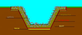
Examples of installation of bolts in the foundation. Legend: 1 – foundation; 2 – gravy; 3 – fixed structure
As mentioned above, some types of anchor bolts can be installed in a finished foundation. To perform this procedure, it is also necessary to first outline the installation locations of such fasteners and calculate the step with which they will be located in the foundation structure. After this, to install the bolts, you need to drill holes, the diameter of which should be several times larger than the cross-sectional size of the fastener itself.
Cement mortar or special glue is poured into the prepared holes, the depth of which should not exceed the height of the foundation structure. Only after this are anchor bolts placed in them and set in a strictly vertical position. After the solution or adhesive composition has hardened, blocks are also formed from the anchor bolts, as described above.
The preparation of the adhesive composition is carried out in accordance with the requirements of regulatory documents
Thus, anchor bolts, designed to reliably connect the foundation structure with the walls of the structure being built, can be installed both in a ready-made concrete foundation and in a concrete foundation that is just being created. If you follow all the above recommendations for the installation and selection of fasteners, they will be able to ensure high reliability of the structure being built and its ability to withstand even very significant loads.
Equipment alignment
3.6. Equipment alignment (installation of equipment in the design position) is carried out in terms of height and horizontally.
Deviations of installed equipment from the design position must not exceed the tolerances specified in the factory technical documentation and in the installation instructions for certain types of equipment.
3.7. Alignment of equipment in height is carried out in relation to working benchmarks or in relation to previously installed equipment, with which the equipment being adjusted is connected kinematically or technologically.
3.8. Alignment of equipment in plan (with pre-installed bolts) is carried out in two stages: first, the holes in the supporting parts of the equipment are aligned with the bolts (preliminary alignment), then the equipment is inserted into the design position relative to the axes of the foundations or relative to previously aligned equipment (final alignment).
3.9. Monitoring the position of equipment during alignment is carried out both with generally accepted control and measuring instruments and with the optical-geodetic method, as well as with the help of special centering and other devices that ensure control of perpendicularity, parallelism and coaxiality.
Rice. 11 Supporting elements for alignment and installation of equipmenta - temporary; b - constant; 1 - release adjustment screws; 2 — installation nuts with disc springs; 3 - inventory jacks; 4 — lightweight metal linings; 5 — packages of metal linings; 6 — wedges; 7 — support shoes; 8 - rigid supports
Rice. 12. Alignment of equipment using squeezing adjustment screws 1 - squeezing adjustment screw; 2 - lock nut; 3 - support plate 4 - foundation; 5 — supporting part of the equipment; 6 - foundation bolt
Rice. 13. Rigid concrete support with a metal plate 1 - foundation; 2 - concrete support; 3 - metal plate
3.10. Equipment alignment is carried out on temporary (alignment) or permanent (load-bearing) support elements (Fig. 11).
The choice of designs for supporting elements is carried out depending on the type of joint and the alignment method. Support elements installed between the foundation and the supporting part of the equipment frame also serve to compensate for inaccuracies in the dimensions and elevations of finished foundations when installing equipment in the design position.
3.11. The following are used as temporary (alignment) support elements when aligning equipment before filling it with concrete mixture:
— squeezing adjustment screws;
- installation nuts with Belleville washers;
— inventory jacks;
— lightweight metal linings, etc.
3.12. When calibrating, the following are used as permanent (load-bearing) support elements that work during the operation of the equipment:
— packages of metal linings;
- wedges;
— support shoes;
- rigid supports (concrete pads).
3.13. The choice of temporary (alignment) support elements and, accordingly, alignment technology is made by the installation organization, depending on the weight of individual equipment mounting blocks installed on the foundation, as well as based on economic indicators.
The number of supporting elements, as well as the number and location of bolts tightened during alignment, is selected from the conditions for ensuring reliable fastening of the aligned equipment before it is grouted.
3.14. The area of support of temporary (alignment) support elements on the foundation is determined from the expression
(1) | ||
| n — | the number of foundation bolts tightened when aligning equipment; | |
| F— | calculated cross-sectional area of foundation bolts, m2. | |
The total load capacity W of temporary (alignment) support elements is determined by the relation
(2) | ||
| G— | weight of the equipment being verified, kgf; | |
| σ0 — | tension of pre-tightening of foundation bolts, kgf/cm2. | |
3.15. Temporary support elements should be located based on the convenience of equipment alignment, taking into account the elimination of possible deformation of the equipment body parts from their own weight and pre-tightening forces of the bolt nuts.
3.16. Permanent (load-bearing) support elements should be placed as close as possible to the bolts. In this case, the supporting elements can be located either on one side or on both sides of the bolt.
3.17. The equipment must be secured in the adjusted position by tightening the bolt nuts in accordance with the recommendations of Section 7 of this Manual.
3.18. The supporting surface of the equipment in the adjusted position must fit tightly to the support elements, the release adjusting screws - to the support plates, and the permanent support elements - to the surface of the foundation. The tightness of the fit is checked with a probe 0.1 mm thick.
ALIGNMENT OF EQUIPMENT USING ADJUSTING SCREWS
3.19. The support plates (Fig. 12) are installed on the foundation in accordance with the location of the adjusting screws in the supporting part of the equipment. The locations of the support plates on the foundations are aligned horizontally with a deviation of no more than 10 mm per 1 m.
3.20. Before installing the equipment, auxiliary supports are placed on the foundation, onto which the equipment is lowered.
3.21. When lowering equipment onto a foundation without auxiliary supports, the adjusting screws must protrude below the mounting surface of the equipment by the same amount, but not more than 20 mm.
3.22. The position of the equipment in height and horizontally should be adjusted alternately with all pressing screws, not allowing the equipment to deviate from the horizontal by more than 10 mm per 1 m during the alignment process.
3.23. After completing the alignment of the equipment, the positions of the adjusting screws must be secured with lock nuts.
3.24. Before grouting, the threaded part of adjusting screws that are used repeatedly should be protected from contact with concrete by wrapping them with thick paper.
3.25. Before final tightening of the foundation bolts, the adjusting screws should be turned out 2-3 turns. When reusing the screws, remove them completely. The remaining holes (to prevent oil from entering) are sealed with screw plugs or cement mortar, the surface of which is coated with oil-resistant paint.
ALIGNMENT OF EQUIPMENT ON RIGID SUPPORTS (CONCRETE PAD)
3.26. Rigid supports (Fig. 13) are made directly on the foundations with an accuracy corresponding to the permissible deviations in the position of the equipment in height and horizontally. Equipment is aligned on rigid supports with machined supporting surfaces. After lowering the equipment onto the supports, it is aligned in plan and secured.
3.27. For the manufacture of rigid supports, concrete of a grade not lower than M200 should be used with filler in the form of crushed stone or gravel of a fraction of 5-12 mm.
3.28. The specific pressure from the weight of the equipment on the support should not exceed 50 kgf/cm2.
3.29. To make supports, a portion of the concrete mixture is placed in a special formwork on a previously cleaned and moistened foundation surface to a level 1-2 cm higher than the required mark. Then the excess mixture is removed and the surface of the supports is leveled.
3.30. To improve the accuracy of concrete supports, metal plates with a machined bearing surface or adjusting wedges are placed on them. The distance from the plate to the edge of the concrete support should not be less than the width of the plate (a>b).
3.31. To make concrete supports with metal plates, the concrete mixture is placed in the formwork to a level that should be 1/2-1/3 of the plate thickness below the design mark. Then a plate is placed on the unset concrete and, with light blows of a hammer, it is immersed to the design mark, verified by a level or other method with an accuracy no less than the tolerance of the size coordinating the working or mounting surface of the equipment. When using adjusting wedges, the error in their height adjustment should not exceed ±2 mm. The horizontality of the plates or wedges is checked using a level placed on the plate sequentially in two mutually perpendicular directions.
3.32. For equipment that does not require high installation accuracy, the use of rigid supports without metal plates is allowed.
3.33. During the alignment process, the height of the support elements can be finely adjusted by adding thin metal shims.
3.34. The installation of the equipment is carried out after concrete has been installed on rigid supports with a strength of 100 kgf/cm2.
ALIGNMENT OF EQUIPMENT USING INVENTORY JACKS
3.35. To align equipment using inventory jacks, screw, wedge, hydraulic or other jacks can be used to ensure the required alignment accuracy, safety and ease of adjustment.
3.36. Jacks placed on prepared foundations are pre-adjusted in height with an accuracy of ±2 mm. Then the equipment is lowered onto jacks.
3.37. When aligning equipment in plan, separation of the base of the jack from the surface of the foundation due to the deviation of the jack from the vertical is not allowed.
3.38. Before filling, inventory jacks are shielded with formwork. Formwork and inventory jacks are removed 2-3 days after grouting. The remaining niches are filled with the composition used for gravy.
ALIGNMENT OF EQUIPMENT ON MOUNTING NUTS
3.39. To align equipment using adjusting nuts (Fig. 14), the bolts must be extended to 6 d
thread, which is provided for in the manufacture of bolts at the request of the installation organization.
3.40. Equipment alignment is carried out either on the installation nuts using elastic elements, or directly on the installation nuts.
3.41. Metal disc, rubber or plastic washers are recommended as elastic support elements.
3.42. The sequence of equipment alignment using Belleville washers (Fig. 14,a) is as follows:
— support nuts with Belleville washers are installed so that the top of the Belleville washer is 1-2 mm above the design mark of the installation surface of the equipment;
— equipment is installed on washers;
— align the equipment using fastening nuts.
In a similar way, alignment is carried out on the installation nuts with elastic elements in the form of rubber or plastic washers.
Rice. 14. Alignment of equipment on the installation nuts using Belleville washers a
— for bolts installed directly into the foundation mass;
b
- for bolts installed in wells of finished foundations; 1 - equipment; 2 - bolt; 3 — fastening nut; 4 - Belleville washer; 5 - installation nut; 6 - foundation; 7 - auxiliary nut; 8 - washer
3.43. Alignment of equipment on installation nuts without elastic elements should be done by adjusting the position of the nuts on the bolts in height. Upon completion of the alignment, the installation nuts are shielded with formwork, which is removed after the concrete mixture has set (2-3 days after pouring). Before final tightening of the bolts, the installation nuts are lowered by 3-4 mm. The remaining niches are filled with the composition used for gravy. This alignment method is applicable if the diameter of the foundation bolts does not exceed 36 mm.
3.44. When aligning the installation nuts using conical bolts with spacer collets (bolt type 11) or with a spacer sleeve (bolt type 12), additional nuts with washers must be installed to secure them in the foundation (Fig. 14,b).
ALIGNMENT OF EQUIPMENT ON PACKAGES OF METAL SUPPORTS
3.45. Packages of metal linings are used as both permanent (load-bearing) and temporary (alignment) support elements.
3.46. The bags are made from steel or cast iron pads with a thickness of 5 mm or more. Achieving the design level of equipment installation is carried out in the process of its preliminary fastening with the help of adjusting pads 0.5-5 mm thick.
3.47. Liners in packages used as permanent support elements must be flat, without burrs, bulges or depressions. In addition to flat ones, the package may include wedge and other height-adjustable linings. The number of pads in the package should be minimal and not exceed 5 pieces, including thin sheets. The surface of the foundation concrete under the lining packages must be carefully leveled. After the final tightening of the bolts, the linings are secured together by electric welding.
3.48. The recommended dimensions of the chocks (depending on the weight of the machines) are given in table. 2. The number of load-bearing pad packages is determined from the conditions of clause 3.4, and temporary ones used for alignment of equipment - according to clause 3.14.
Types of anchor bolts
There are various types of anchor bolts on the market to solve different problems. There are both universal devices and highly specialized samples.
In order to choose the right anchor fasteners, you need to understand the classification and scope of application of each sample when performing construction work.
Among the most common types, the following options should be highlighted:
- With a nut. This variety is considered the most popular fastener. This hardware includes a threaded rod, a spacer sleeve and a nut. According to the principle of application, this fastening element is distinguished by its simplicity and reliability. The structure is placed in the hole, and when a special nut is tightened, the conical tip opens the spacer sleeve. To increase ease of installation, manufacturers offer hardware with different sizes of nuts.
- With a hook. The clamp of this sample differs from the anchor bolt in one detail - the presence of a hook. This component allows installation work of different levels of complexity. Often, hardware is used to ensure high-quality coupling of hinged elements. The design also includes a nut that operates the release mechanism.
- With a ring. The next option is identical in principle of installation in the base, however, it is distinguished by the presence of a special ring. Thanks to the closed mechanism, it becomes possible to fasten structures and individual elements of large mass.
- Double-spaced options. These anchors have one important feature - the presence of two spacer bushings. The operating principle is significantly different from previous hardware. When tightening the mounting nut, one bushing gradually fits into the other, which ensures the mechanism opens.
Installation of bolts and connection principle
The installation process is practically no different from the methods of fixing conventional hardware. But it is necessary to take into account several certain rules:
- First, you need to drill a hole in the structure. In this case, attention should be paid to selecting the optimal diameter. It must match the transverse dimension of the spacer sleeve.
- Clean the hole from foreign objects, splinters and dust. To clean quickly and efficiently, use a vacuum cleaner or a medical blower.
- Having measured the distance from the edges, it is necessary to install the mounting anchors in the mounting locations. If the hardware does not fit well in the holes, use a hammer. The main condition is that the anchors must enter with force, which determines the correct ratio of the diameter to the dimensions of the fastener.
- After installing the hardware, begin the process of unclamping the bushings. The elements are activated thanks to threaded parts.
The connection principle directly depends on the selected type of hardware.
Installation conditions and recommendations
The foundation hardware is supported by:
Friction creates a load that acts on the fastener. The foundation is glued to the bolt with glue or mortar; this compensates for the force of impact and ensures its uniform distribution. The acquisition of the necessary elements is carried out after determining by calculation the diameters, lengths and the required quantity for reliable fastening. Parts of small length will be needed in areas not subject to shock and vibration. Bolts with a diameter of 6 cm require an increase in the mass impact on the connection point, and with dynamic forces acting, the parameters are increased.
The type of elements depends on the climate of the region. In the Northern regions with low temperatures, low-alloy steel is used for production.
Builders perform accurate and correct installation according to a previously drawn up detailed diagram. They provide for the distribution of fasteners with a distance between adjacent elements and their immersion in depth. To prevent the foundation from being deformed, the installation is carried out moving away from its edge. According to the standards, the location of the bolts should not be less than the immersion value.
A reliable installation is considered to be the installation procedure at the time the foundation is laid out; the concrete firmly holds the hardware that connects the structure. Place the bolts vertically in the uncured solution at the same depth. After the concrete has hardened, they are tied together using metal strips. The immersion must correspond to the foundation thickness; the product is lowered without exceeding half the value of this parameter.
Production is also carried out in a finished foundation block. For installation, holes with diameters exceeding the size of the bolt are drilled. The master knows the distribution of reinforcement in the base and, when performing the procedure, bypasses these areas so as not to destroy the structure. After the process is completed, the recesses are filled with concrete mixture or adhesive.
Builders consider glue to be a more reliable method for adhesion. Then install the fastener vertically.
Such installation work is used when its production is necessary, but not planned. For this purpose, you will need hardware with conical ends with a thickening on the rod. As the part is tightened, the collet expands with a reliable grip. The fastening is applicable for light objects that do not create vibration processes during operation.
Correctly selected foundation bolts allow entire enterprises to operate without accidents. Competent settlement operations in this area will help to eliminate emergency situations. Directories and regulatory documentation will always point in the right direction; they combine the work of research groups based on examples from emergency situations.
Noticed a mistake? Select it and press Ctrl+Enter to let us know.
Calculation of foundation bolts, characteristic features of use
Calculation of foundation bolts, instructions on the necessary parameters, design data are presented in building codes and regulations. The manual for them contains
Working principle and application
Concrete is a porous material with a heterogeneous structure. And in the places of fastening, various forces appear - twisting, bending, shearing, shearing, compression, tearing. The concrete anchor takes over them, distributing them together with the supporting structure.
Basic principles of operation of concrete anchors:
- At the moment of interaction between the base material and the anchor, a frictional force appears - the expansion is carried out with dowels and metal collets.
- When, at the depth of anchoring, the material provides resistance to fracture or crushing - due to collet bushings on the fasteners, the curved shape of the rod, and expansion.
- Loads at the point of contact between the base and the rod are compensated by tangential stresses during embedding or gluing - this is how smooth, adhesive anchors work.
Anchors for concrete can be of different designs, types, sizes. They are made from special steel according to GOST and coated with a layer of anti-corrosion agent. The rod can be 6-20 millimeters in diameter and up to 220 millimeters long.
Any anchor includes the following parts:
- The bolt itself
- Cone with a layer of thread inside
- Bushing with special cutouts
Anchors perform a constructive or load-bearing function. The load-bearing function is implemented in cases of connecting floor slabs, beams, columns, balcony consoles, landings and flights, finishing and wall panels, engineering equipment, communications, hoods, ceiling lamps, etc. Anchors are also used for installing joists on concrete or hollow-core floors. They are used to attach electrical equipment and hanging furniture to walls.
Structural fasteners are used to counteract the displacement of parts of the assembly if their stability is guaranteed by their own weight; anchors are also relevant when straightening in construction.
How to install an anchor bolt
Before attaching an anchor bolt with a nut, it is necessary to drill a hole, the diameter of which must be equal to the thread parameter.
After cleaning the hole from dust, the anchor is installed into it, with the conical part directed inside the hole, the length of which slightly exceeds the minimum depth for anchoring. Using a hammer, the anchor is inserted until the required installation depth is reached, after which the nut is tightened. After ensuring the required tightening torque, which is best controlled using a torque wrench, the nut is unscrewed, a suspended structure (for example, a stand for diamond drilling) is installed on the stud, and the nut is tightened.
Calculation of anchor and foundation bolts
ST. PETERSBURG STATE
POLITECHNICAL UNIVERSITY
Department of Building Structures and Materials
Guidelines
For a course project (course work)
Discipline: “Metal structures”
Topic: “Design of the base of an eccentrically compressed column of an industrial building”
Developed by: Associate Professor Timofeev N.M.
Saint Petersburg
G.
This section is part of the section “Design of a solid eccentrically compressed column of a one-story industrial building” and is an addition to the guidelines for completing a course project (course work) on the topic “Design of the frame of a one-story industrial building without a crane load.”
This manual examines the design of a base for a solid-wall column of a composite cross-section with a double-walled traverse and rigid support on the foundation, gives the concept of non-alignment installation of columns, a detailed description and calculation of all elements of the base, and provides all the reference data necessary for designing a base of this type.
MU is focused on independent work of students.
Column base design
The base is the supporting part of the column and serves to transfer forces from the column to the foundation. The structural solution of the base depends on the type and height of the column section, the method of supporting it on the foundation and the adopted method of column installation.
The initial data for designing the base of the column is: the geometric dimensions of the cross section of the column at the base, the calculated values of the bending moment “M”
and normal force
N"
in the section at the level of the base of the foundation slab.
Here we consider only rigid support corresponding to the embedment in the design diagram. Figure 1 shows the design of a base with a double-walled traverse.
Rice. 1 Column base with a double-walled traverse.
The design of the column base is shown in Fig. 1. The column base consists of the following main elements: base plate-1, resting on a reinforced concrete foundation-2 and additional stiffeners-8, transmitting compressive force to it, traverse-3, covering the column rod from the sides, anchor bolts-4 and anchor tiles-5 or support I-beams-6, straightening bolts-7,
- The concept of non-calibrated installation of columns
There are two ways to install a column on a foundation: with alignment of the column during installation and without alignment. The latter method has clear advantages over the first, but requires the manufacturer to have equipment for milling the end of the column and gouging the upper surface of the slab, so the workpiece (sheet or slab) must have a thickness 2-3 mm greater than the calculated one. The alignment of the slabs is carried out using an instrumental method, and the installation of the slab in a horizontal position is carried out using installation (straightening) bolts (detail A in Fig. 1). After alignment, cement mortar is poured under the slab, for which there is a hole (holes) in the slab with a diameter of about 100 mm at the rate of 1 hole per 0.5 m2 of slab area.
After the design strength of the grout solution has been achieved along the axial marks on the base plate, the column is installed. Supporting I-beams or anchor tiles are installed on the anchor bolts, already concreted into the foundation, and the anchor bolts with nuts and washers are put on, tightly pressing the traverses to the base plate. With this installation method, the column is installed in the design position without alignment.
Upon completion of installation work, the base of the column is monolid to the level of the finished floor of the production room.
Column base calculation
3.1 determination of the planned dimensions of the base plate
The side overhangs of the slab are taken structurally. asv= 60÷100 mm,
traverse thickness
tr = 14-16mm .
Thus, the width of the slab is: bpl= bп+2асв+2
tr
, where
bп
is the width of the column flange. The resulting size bpl is rounded to the nearest standard width of rolled sheets, table 5.
Base plate length lpl
determined by calculating the strength of the foundation concrete.
Having specified the class of foundation concrete, Table 1, determine the calculated compressive resistance of concrete Rb
Calculation of anchor and foundation bolts
Calculation of anchor and foundation bolts ST. PETERSBURG STATE POLYTECHNIC UNIVERSITY Department of Building Structures and Materials Guidelines K
Methods for supporting equipment on a foundation
3.1 (3.1). Depending on the method of supporting the equipment on the foundation, there are three types of foundation-equipment joint designs (Fig. 10):
a) using packages of flat metal pads, wedges, support shoes, etc., with adding concrete mixture after securing the equipment (type 1);
b) with the equipment resting on a concrete base with “no support” installation methods (type 2);
c) with equipment supported directly on the foundation (type 3).
Rice. 10. Designs of foundation-equipment joints
a - with equipment supported on metal bags (type 1); b - resting on a concrete base with a non-supporting method of installing equipment (type 2); V
— with equipment supported directly on the foundation (type 3): 1 — equipment; 2 — metal bags; 3 - concrete gravy; 4 — adjusting (installation) bolts; 5 - foundation
3.2 (3.2). When using a joint of type 1, the transfer of installation and operational loads to the foundation is carried out through individual elements used as permanent supports (metal bags, support shoes, etc.), and the grout has an auxiliary, protective or structural purpose.
If it is necessary to adjust the position of the equipment during operation, topping may not be performed, which should be provided for in the installation instructions.
3.3 (3.3). When installing equipment using packages of flat metal pads, support shoes, etc. as load-bearing support elements. ratio of the total contact area of the supports ( F
op) with the surface of the foundation and the total cross-sectional area of the bolts (F) must be at least 15.
3.4. (3.4). When using joint designs of type 2 or 3, operational loads are transferred to the foundation, respectively, through a concrete filler or through a calibrated foundation surface.
3.5. When securing equipment to foundations, unsupported installation methods are predominantly used (joint designs of types 2 and 3).
In cases where the supporting area of the equipment is less than 15 times the area of the bolts, the contact surface with concrete should be increased by installing permanent supports, i.e. joints of type 1 should be used.
The design of the joints is indicated in the installation drawings or in the equipment installation instructions and is taken into account when calculating the foundation bolts.
In the absence of special instructions in the instructions of the equipment manufacturer or in the foundation design, the design of the joint and the type of supporting elements are assigned by the installation organization.
Anchor fasteners for foundations - characteristics and where they are used
Foundation bolts are used to secure heavy structures and equipment to concrete. They provide strong adhesion, and the reliability and service life of the building depend on them. They are used for repairing old foundations, connecting extensions to the house, fixing a prefabricated grillage with piles, installing stationary equipment and hanging heavy equipment.
Characteristics, types and sizes
Anchor bolts are used to fasten particularly loaded elements and structures, so their strength is subject to strict requirements established by GOST. Only high quality steel is used for production. A zinc layer is applied to protect the rod. Galvanization is done by galvanic or thermal diffusion method. The second method is considered the best option, as it creates a more reliable and durable coating.
The following types of foundation bolts are produced:
1. Composite anchor. They are used when installing equipment on the foundation by turning or sliding. The lower stud with the slab and coupling is placed before pouring the concrete solution. Then the top pin is screwed in and secured by welding. Composite anchor bolts are installed before concreting. Available in diameters 24-64 mm. The total length depends on the parts being connected.
2. Bent foundation bolt. The scope is the same; it is used for mounting equipment and other structures to a reinforced concrete base. Consists of two nuts, studs and washers. It differs from a conventional fastening element in that the end of the rod is bent at a right angle. It is manufactured in two versions: in the shape of the letter L and with a slightly deviated pin to the side (another name for “swan”). The first type is installed before pouring the concrete solution, the second is installed in the wells of the finished foundation and sealed with the mixture. Sold in lengths from 30 to 180 cm, diameter 12-48 mm. The main advantage of curved fasteners is their simple production method. For places with harsh climatic conditions (high humidity, cold) they are made of alloy and low-carbon steel.
3. With anchor plate. Scope of application: solid foundations. They are used to install load-bearing and metal systems. The length of the anchor bolt with a plate starts from 20 cm and reaches 4 m. Diameter is 16-160 mm. Its use is acceptable in both civil and industrial construction. Foundation bolts are installed with the slab before pouring the concrete mixture. Thanks to their characteristics and non-standard design, they can be used for fastening not only in reinforced concrete structures, but also in foundations made of brick and stone.
4. Removable. It consists of a rod, one end of which has a thread, and on the other there is a special mount for holding in concrete. Fixed with embedded plates. It is used in the construction of residential and industrial reinforced concrete, stone, brick or concrete structures. To produce removable bolts, high-strength steel is used that can withstand significant loads and high tensile forces. During installation, only the anchor reinforcement is placed; the remaining elements are screwed in after final installation.
5. Anchor straight. The fastener has a standard stud. It is installed in the finished hole, after which it is covered with epoxy glue or a cement-sand mixture. A straight foundation bolt with a diameter of 16-42 mm and a length of 30 to 170 cm is available. It is made of high-strength steel, so it can withstand significant mechanical loads. Used for fastening equipment and various structures to strong, inelastic foundations.
6. With a tapered end. The upper part of the fastener looks the same as that of a straight anchor. At the opposite end there is a conical part that is capable of self-wedging. Produced with a diameter of 12-48 mm. Mounted with an expanding collet or cement-sand mixture. These fasteners are highly durable and resistant to corrosion.
The scope of bolts depends on their type and size. The length can be any, and the fastener can be made to order for a specific structure.
Foundation anchor bolts purpose, types and installation
To ensure high-quality fastening of load-bearing structures and other elements to the foundation, craftsmen use special foundation bolts. Such products are manufactured in accordance with clearly established GOST requirements.
Steel fasteners act as an anchor, which is mounted into a cement base, creating a reliable connection. Due to their characteristic shape and high strength, hardware is able to withstand dynamic and static loads.
Manufacturers produce several types of foundation bolts:
- Curved bolts – meet the requirements of GOST 24379.1-80. Made from durable metal, the end of the rod is bent 90 degrees. These fasteners are limited to a length of 180 cm.
- Bolts with an anchor plate are characterized by large sizes - up to 500 cm. Such hardware is used to fix reinforced concrete foundation structures. At the bottom, the bolts are equipped with a nut that is capable of fixing the anchor plate to the base.
- Composite fasteners comply with GOST 24379.1-80 standards. The hardware includes: threaded rod, pin, coupling and anchor plate. It does an excellent job of fixing elements of various sizes.
- Removable foundation bolts have a special metal structure, which is equipped with an anchor-type system. Thanks to this, hardware can be used for installation in stone, concrete and brick foundations.
- Direct hardware is the simplest of those listed. They are a pin with threaded fixation on one side. The length of such devices is up to 140 cm.