The exact technical definition of a gearbox is a device for converting mechanical energy in terms of parameters. It has characteristics of input and output indicators. In practice, the gearbox can not only change the kinetic parameters and levels of energy transfer, but also change the direction of rotation and following of the shafts.
Today, a gearbox is considered in terms of a device that is used to change the shaft rotation speed relative to the drive mechanism. At the same time, the possibility of increasing torque or ensuring an extremely low number of revolutions with very serious efforts can be considered. By design, gearboxes are divided into:
- cylindrical;
- conical and conical-cylindrical;
- worm;
- planetary;
- combined, in which several conversion schemes are used simultaneously.
To understand how suitable a particular type of gearbox is for solving the tasks assigned to it, it is worthwhile to dwell in detail on the features of their operation and conditions of use.
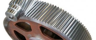
Helical gearbox: general information
The helical gearbox is the most common type of converter mechanism. It has the main characteristic: the input and output shafts are strictly parallel, but not necessarily coaxial.
The advantages of a helical gearbox include:
- high efficiency, energy losses are minimal;
- does not have self-braking, it is always possible to rotate the output shaft even with little force;
- can transport high power;
- has kinematic accuracy;
- practically do not heat up, without requiring special cooling conditions;
- Products are produced with different gear ratios and conversion stages.
Due to the presence of a large range of products on the market, it is not difficult to select a spur gearbox with the desired gear ratio for use in a particular mechanism.
Types of gearboxes
Helical gear mechanisms can be classified according to a number of characteristics. The main ones are the types of thread, the number of stages, the type of wheels, etc. For example, taking into account the type of wheels, gearboxes are:
- helical;
- straight teeth;
- chevron;
- curvilinear.
Straight teeth are the easiest to manufacture, but are noisy when compared with the same chevron or helical ones. As a result of strong constant shock loads when paired tooth connections come into contact, vibration is produced - the main cause of severe wear of the unit. Helical type wheels are more complex than spur ones, but their performance parameters will be better. This is manifested by minimal wear, low noise, and smooth operation.
Taking into account the nature of the shaft arrangement, spur gearboxes are divided into:
- intersecting axial;
- parallel-axis.
- Types by number of degrees:
- single stage;
- two-stage;
- multi-stage.
The choice of the number of stages depends on the gear ratio created by the gearbox. By using different arrangements of stages in the gearbox, it is possible to obtain any required arrangement of the input and output shafts relative to each other.
Possible transmission options in a helical gearbox:
- forked; expanded;
- coaxial
How does a helical gearbox work and where is it used?
The basis of the design of a helical gearbox is gear wheels in the shape of cylinders. The coaxiality (location of the axes of machine parts (assemblies, assemblies, etc.) on the same line) of the input and output shafts depends on the number of transmission stages. In the simplest version, there are only two spur gears inside the housing. In this case, the displacement of the output shaft from the input shaft axis is determined as the sum of the radii of the wheels along the outer contour minus the depth of the teeth.
The alignment of the input and output shafts is achieved by using several conversion stages. In this case, an odd number of cylindrical gears are located inside the housing, some of which are auxiliary. They can serve as a simple transmission mechanism without conversion, or have a gear ratio to reduce the load on the teeth and increase the service life of the mechanism.
Helical gearboxes are produced in closed housings; most of them do not require special maintenance. The scope of application of these devices is extremely wide. They guarantee smooth transmission, but do not allow changing the direction of the shaft.
Helical gearboxes can be located vertically or horizontally; calculation of load and speed is simple: high efficiency allows the use of the gear ratio specified by the manufacturer in arithmetic operations. The main advantage of the gearbox is the conversion of drive energy with virtually no distortion or loss.
Drum motors and gear motors in conveyor drives
Motor drums
A common solution for belt conveyors is the use of drum motors - compact devices consisting of a built-in electric motor, gearbox, terminal box for connecting to the electrical network and a drum housing. This design is convenient due to the following factors:
- Compact dimensions, which is convenient for direct portable and mobile conveyors.
- Complete sealing of the outer casing, which is the main requirement for ensuring durability when working in conditions of high humidity and aggressive environments.
- Ease of use in enterprises with high requirements for cleanliness of the workspace, for example the food industry. The use of a drum motor makes it possible to exclude contact of moving mechanisms and lubricants with the external environment without additional protective measures.
- Reliability of the design due to the absence of distortions in the shaft of the electric motor, gearbox and drive drum, as well as the absence of safety clutches in the design.
- This conveyor drive is easy to install due to the absence of the need for alignment and connection of all elements. It is enough just to install the shaft journals into the corresponding grooves of the conveyor frame.
- High efficiency due to a minimum of connecting elements.
- Minimal wear and noise during operation of the device.
- Low weight due to the absence of a special frame, cast iron body and couplings.
All together, this ensures ease and convenience of operation, economical energy consumption and higher efficiency compared to other types of drive of equal power. An important advantage is the dust- and waterproof design, which is convenient for use outside or in dusty and damp rooms.
The above advantages have ensured this type of conveyor drive is widely used in belt transmission mechanisms of various types and purposes. Let's briefly look at the main elements of the drum motor:
- The drum has a barrel-shaped surface, which ensures centering of the belt during equipment operation.
- Shaft mounting journals with reliable sealing for connection to the conveyor.
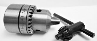
- Gears and bearings. Gear transmission is ensured by stamped gears made of high-quality steel, with a hardness of the order of HRC 60–62.
- Terminal box. It is made of gray cast iron and has high dust and moisture protection.
- An electric motor whose stator rotates at the required frequency, and the rotor wings act as fans.
Motor-drums for the conveyor drive are available both in a standard version and with special insulation that protects against moisture and acid vapors, explosion-proof devices, systems with pole switching, etc. To prevent reverse motion of the belt when operating inclined devices in the event of drive failure special rollback locks are used, the function of which is performed by roller freewheel clutches (overrunning clutches).
Geared motors
Mounted geared motors are no less widely used than motor-drum drives. They are used in belt, scraper, plate and other types of conveying machines. Typically, the drive of this type of conveyor is mounted onto the drive shaft of the transport mechanism by means of a hollow gearbox output shaft. As a rule, torque arms are used as rotation protection. These devices, on the one hand, are rigidly fixed to the gearbox housing, and on the other hand, through a damper, with stationary elements of the equipment.
The main advantages of mounted geared motors:
- The mounted conveyor drive, in comparison with a conventional design, makes it possible to reduce the dimensions of the device and provide a more convenient layout.
- Significant reduction in the weight of mechanisms, which is especially important for portable conveyors.
- Simplification of installation and dismantling operations.
- Simplify and reduce maintenance costs.
- Simplified design due to the absence of a rigid connection with fixed elements (feet, flange, etc.)
Various options for mounting geared motors in conveyor drives are possible using various designs of hollow gearbox output shafts:
- Hollow shaft with keyway. It is used for continuously operating conveyors with a uniform applied load.
- The shafts are hollow without a spline and are secured by a shrink disc to the driven shaft. They are used for shock loads and a large number of starts and stops.
- Spline shafts.
Various types of gearboxes are also used to drive mounted conveyors, in particular flat cylindrical gearboxes with parallel input and output shafts, worm gearboxes, bevel gearboxes and spiroid gearboxes.
Often, a design solution is to install two drives that ensure rotation of a common shaft. This allows for higher efficiency during operation, but significantly complicates the design due to the need to ensure synchronous rotation and uniform load distribution on each conveyor drive.
Conveyor drive motors
Despite the fact that conveyor drives differ in technical characteristics and design features, electric motors meet similar requirements, which allows them to be combined into one design group. First of all, there is no need for speed control for most transport vehicles. Less often a small adjustment within the range of 2 to 1 is required, and even less often higher rates are required.
As for environmental conditions, the electric motors that drive the conveyor drive in many cases operate in dusty or humid areas, at high or low ambient temperatures. It is also possible to work outside, in aggressive environments, etc. This must be taken into account when selecting equipment.
The conveyor drive, as a rule, operates under conditions of high static moment of resistance. Often it exceeds the nominal torque due to various reasons, not least of which is the thickening of the lubricant in the friction units. Therefore, the electric motor must meet high requirements for reliability and ease of maintenance. It must also provide high starting torque.
Depending on the design and scope of application, there are additional requirements, such as:
- smooth start;
- slight speed regulation;
- preventing belt slipping;
- synchronous rotation of several electric motors of conveyor drives, etc.
To solve these and many other problems, asynchronous electric motors with a squirrel-cage or wound-wound rotor are optimally suited.
When designing a conveyor drive, the power of the electric motor is selected using a gradual approximation method in parallel with the calculation and selection of all equipment.
- First, the traction force and tension are approximately calculated.
- Next, based on these data, a preliminary selection of motor power and mechanical equipment is made.
- At the next design stage, a refined graph of the dependence of the belt tension is created, taking into account losses versus length.
- And the design is completed by choosing the location of the electric motor, gearbox and other drive elements, and checking the equipment for the current forces and tension.
The main features of the layout and location of conveyor drives are indicated above, in the corresponding section of this article.
The main component of the design of conveyor drives is the traction diagram. To do this, the route of the transport vehicle is drawn, with the exact location of all elements and configuration features. Then the losses in each section are determined, and based on this the traction tension along the entire length is calculated.
After constructing the diagram, the optimal place on the route where the conveyor drive should be placed is determined. When the transport mechanism is long, several drives with separate electric motors are installed to evenly distribute and minimize effort.
Features of bevel and bevel-helical gearboxes
The operation of bevel and bevel-helical gearboxes has the same features and basic characteristics as cylindrical devices. The main difference is in the shape of the gears inside the housing.
As the name suggests, a bevel gearbox has all gears of a conical shape; a bevel-cylindrical gearbox has elements of both types in its design.
Gearboxes of these classes have their own characteristics:
- capable of changing the direction of the shafts, a bevel gearbox with one conversion stage provides a rotation of 90 degrees;
- the force during gear operation is directed at an angle to the shaft axis. Therefore, bevel and bevel-helical gearboxes must be secured separately to avoid lateral pressure on the drive axis. This may somewhat complicate the design of mechanisms with their participation.
The types of gearboxes under consideration are used only in cases where it is impossible to do without changing the direction of the shaft. These devices are expensive, which is easily explained by the increased complexity of manufacturing gears and the need to guarantee the accuracy of the assembly of the gearbox as a whole.
But otherwise, the devices operate almost silently, products are offered with different gear ratios, they do not require special maintenance, and their service life is very long. The rules for calculating the output shaft speed and torque are the same as for helical gearboxes.
Helical gearboxes - types and definition
The cylindrical gearbox got its name not due to its cylindrical shape. The basis of the name was the cylindrical operating diagram of the unit, namely the cylindrical shape of the gear wheels used in the design. Inside the gearbox, in two or more rows, there are several transmission wheels with one (at least) cylindrical gearing.
The word gearbox translated from the Latin word reductor means leading (leading) back. This fully characterizes the main quality of the devices - the removal of rotating force. The transmission in cylindrical gearboxes can be direct, chain or gear.
A cylindrical gearbox is a mechanical system assembled for the purpose of transmitting and converting torque. The system is capable of converting a high angular velocity into a lower one with high efficiency with an increase in torque, i.e. an increase in the transmitted force. When we add an electric motor to the system, we get a cylindrical gear motor - a compact device that creates and converts torque.
The transmission of torque in spur gearboxes can occur in different planes and at different angular positions of the shafts relative to each other. Depending on the angle of inclination of the gear teeth, the devices under consideration are divided into cylindrical spur and cylindrical helical gearboxes.
As the name suggests, a spur gearbox has a straight tooth shape of the gear wheels, i.e., located parallel to the axis of the gear wheel. This ensures simultaneous engagement along the entire length of the teeth. The advantage of this type of engagement is the high transmitted power and the possibility of slight displacement of the wheels relative to each other. The disadvantage is higher wear (compared to helical gears) and increased noise. Spur gears are used in both open and closed gears - single-stage cylindrical gearboxes, as well as two-, three-stage, etc. The number of stages here means the number of gears.
With helical gearing, the axes of the teeth are at an angle to the axes of the gears. Thus, the engagement process is a gradual capture of each subsequent tooth. This increases transmission efficiency and reduces noise and vibration during operation. One-, two-, three-stage cylindrical gearboxes, as well as devices with a large number of stages, are also produced with helical gears.
Worm gearboxes: general information
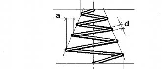
The mechanics of a worm gearbox is based on the idea of transmitting torque from a specially threaded screw to a gear wheel.
In this case, during the operation of the mechanism, significant friction forces are formed between the surfaces of the worm and the tooth of the shaft drive mechanism.
As a result, the device generates a large amount of heat, requires special cooling conditions, and has a low mean time between failures.
Over time, due to the destruction of drive elements, backlash and increased heat generation may occur.
The advantages of a worm gearbox include:
- smooth running of the output shaft;
- large transfer coefficients;
- To perform the tasks assigned to some mechanisms, the self-braking property of the gearbox is useful: the shaft cannot be rotated when the drive is turned off.
The worm gearbox has a significant list of disadvantages. In addition to those already mentioned (significant heat generation, low service life), these include:
- reduced efficiency, which drops during operation due to wear and tear of the mechanics;
- Fine adjustment and tuning is required.
The worm gearbox requires separate mounting during installation to ensure that there are no parasitic multidirectional forces acting on the output and input shafts. If this condition is not met, the service life of the device may be reduced compared to that declared by the manufacturer.
Where are worm gearboxes used?
Worm gearboxes are most often used in mechanisms that require the transmission of low power with a large conversion ratio. For example, devices with weak high-speed engines that provide a small number of strokes or revolutions of the executive body.
Many mechanisms may require a low angular speed of rotation of the output shaft. In this case, a worm gearbox will be ideal. It guarantees significant output torque, and thanks to the huge gear ratio, the output speed is very low. These can be gate drives, various lifts of a lever design.
To solve some problems, a feature of worm gearboxes may be useful, which consists of changing the direction of the output shaft relative to the input shaft by 90 degrees. This indicator never changes.
Separately, it is worth noting the combined gear reducers. They carry out a double conversion: preliminary using a cylindrical circuit and final - using a worm gear. This achieves an even higher conversion factor for the lowest angular velocity of the output shaft.
Scope of application of helical gearboxes
Due to their high technical and operational characteristics, spur gearboxes are widely used in various fields of activity, especially in mechanical engineering and the automotive industry. This type of device is used in various industrial equipment - taps, mixers, machine tools, extruders and much more. other machines and mechanisms. The limitation for the use of devices is the need for smooth running of machines and mechanisms, as well as small sizes with a large gear ratio of steps.
Planetary gearbox: general information
The design of the planetary gearbox allows it to operate in two modes: as a rigid converter of mechanical energy and as a model of a summing mechanism that selects torque from two drives. The advantages of a planetary gearbox include:
- compactness;
- universality of application of output torque, both for driving shafts and for transmitting rotation to gears;
- light weight;
- high efficiency.
The disadvantage of a planetary gearbox is its high cost. This is due to both the large number of parts in the conversion mechanism and the requirements for high precision in their manufacture.
Bevel-helical gearbox
This type of gearbox belongs to the classic design options. Its main purpose is to convert or change the speed of rotation of the shafts, usually from higher to lower. Thanks to the conical configuration of the working parts, effective transmission of torque from one shaft to another is ensured, regardless of the approach angle parameter. The cylindrical gearbox with bevel gear differs favorably from other designs in its increased efficiency and high operational reliability. These device qualities have a direct impact on the technical parameters of the entire mechanism in which this gearbox is used. For example, the performance of the entire device largely depends on the number of gears in the mechanism. Therefore, depending on the design requirements, single-stage devices are used, as well as bevel-cylindrical two-stage and multi-stage gearboxes.
As an example of such a gearbox, we can take the horizontal arrangement of cylindrical gears, which is most suitable for operation in the following conditions:
- constant or variable load;
- long or short-term operating modes;
- multidirectional rotation of shafts.
This single-stage helical gearbox is limited to a maximum speed of 1800 rpm. An important advantage is the compact size of the device and low weight - up to 250 kg.
How does a planetary gearbox work?
The transmission of rotation in a planetary gearbox is carried out from the gear, which the drive rotates, to the outer circular element - the epicycle. The conversion factor depends on the ratio of the number of teeth on the sun gear and planetary gears.
The gearbox diagram is shown in the figure:
When the carrier, indicated in green, is rigidly fixed, the planetary gearbox works as a simple converter of the mechanical energy of one drive. The second use case is to rotate the sun gear and carrier from different sources. In this case, the energy is summed up, and the calculation of the final power on the epicycle is quite complicated.
Where is the planetary gearbox used?
Due to its small size and smooth running, planetary gearboxes are recommended for precision mechanisms. A wide range of products are offered on the mass market. Gearboxes are available with different conversion ratios that can transmit more power by reducing the angular velocity of the output device. This can be extremely useful in metalworking machines.
Planetary gearboxes show good results in various lifts and conveyors. They are able to provide a smooth change in power with minor load surges on the drive. To ensure high power of conveyors, additional drives with planetary gearboxes in summation mode can be used, which can ensure the creation of long, highly loaded conveyors or lifts.