Geared motor design with calculations
The geared motor is selected according to special engineering calculations. Complex design studies are not required, since standard calculation schemes are used, taking into account several basic indicators. The most important of them are the permissible torque on the output shaft and the speed of rotation.
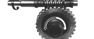
Figure No. 1. Worm gear device
Calculations when selecting a gearmotor are simpler than when installing the gearbox and electric motor separately. There is no need to precisely coordinate these mechanical components. All characteristics can be divided into mechanical and electrical (electric motor power requirements).
The mechanical alignment of the axes of the gearmotor and the drive mechanism is ensured by a coupling and bolted connection of the crankcases. End mounting is very convenient, but this method is only suitable for compact models, for example, for a planetary kinematic scheme.
Figure No. 2. Planetary gear design
Basic kinematic diagrams of geared motors
- Worm . It has the lowest cost in terms of gear ratio. Only one stage of the worm gear can give a gear ratio of up to 50-80. A two-stage one already gives 50-10,000, but in practice such gearboxes are rarely needed.
- Cylindrical . The best option for high power. It is the gearbox with spur gears that provides the greatest efficiency and service life. All industrial systems that require high drive power are equipped with spur gearboxes, for example: crushers, rolling mills.
- Planetary . The best option for compact geared motors. The planetary kinematic scheme combines all the advantages of the cylindrical scheme, except for low cost and ease of manufacture. Planetary gearboxes of general industrial design are installed on metalworking machines.
There are other, less common gear reducer designs: bevel, a combination of bevel and helical (bevel-helical gearbox) and a combination of worm and helical. Combined circuits are used in special-design gearmotors: drive of conveyors, sorting drums, assembly lines.
Figure No. 3. Spur gear design
A special version of the gear motor is wave gear. It differs significantly from all other types in that the engagement is carried out through a flexible gear wheel. This scheme is suitable for small and medium loads. The resource of the flexible wheel is small, but for most applications it is sufficient. Wave gearboxes can have a gear ratio the same as that of two-stage worm gearboxes, while their efficiency is much higher. They can already be used in fairly heavily loaded drive systems, for example, for compact drilling rigs.
Geared motors for constant loads
To drive machines and mechanisms with continuous operation, it is necessary to select gearmotors with a power reserve. The most profitable operation will be with a small power reserve. If it is made too large, energy will be wasted, plus the drive system itself will become too expensive.
In helical gearboxes, the efficiency is the same when rotating in both directions. It differs for worm and conical ones. That is why manufacturers offer right- and left-hand versions. It is also possible to release the input and output shafts in the required directions. Assembly options are specified when ordering. Since they are assembled from the same parts, the cost will also be the same, regardless of the specific assembly option.
Geared motors for cyclic loads
A significant number of production mechanisms operate cyclically. Their load is not constant, which allows the gears of the gearbox to cool. Especially for such tasks, manufacturers indicate operating time schedules depending on the load. When selecting, these indicators must be taken into account.
Specialized gearboxes for rolling equipment
Rolling metal requires extremely significant effort. The torque of such drive systems is thousands and tens of thousands of times higher than that of, for example, cars. In fact, the torque is limited only by the strength of the metals (about 5000 kg/cm).
If in other areas of industry it is possible to use universal gearboxes, then for rolling equipment only specialized solutions are suitable. Let us consider just such drive systems for rolling mills of any power, produced by the Elektrostal Heavy Engineering Plant (EZTM gearboxes). Since this is a very specialized type of product, it is produced in small batches, but to reduce production costs, an increase in the number of batches is required. Therefore, the products are popular in more than 40 countries around the world, including such metallurgical giants as China.
Drive units for seamless pipe production lines
Hot-rolled seamless steel pipes have the greatest strength. This production method is convenient for large pipe wall thicknesses. It is this technology that is used to make oil and gas pipes (tubing pipes). Their rolling requires significant mechanical effort. The main mill stand is driven by high-power spur gearboxes. The cylindrical circuit is the main one. To drive auxiliary mechanisms (conveyors, pipe feeding), you can use all other types of gearboxes, for example planetary and worm gearboxes.
A mandatory element of a pipe rolling mill is a piercing machine. To ensure the piercing of heated steel blanks for pipes, a torque of 1000 kN (1 million N) is required. The piercing mill is driven by a so-called chevron gearbox. Large ring gears are manufactured separately from the wheel.
Gearboxes for long-rolling machines
Long products have a larger cross-section (in sq cm of metal) than pipes. In this regard, the rolling force also needs to be increased. A specialized cylindrical gearbox is installed on each stand. The smaller the diameter of the workpiece, the lower the required rolling force, but due to the increase in the number of technological operations per ton, the cost does not decrease (in terms of weight). That is why for massive structures (high-rise buildings, bridges) they try to use reinforcement and rolled products with a large cross-section. Their production is possible only on large rolling mills with gearboxes with a torque of 1000 kN or more.
Go to the catalog of geared motors
Types of gearboxes
These devices differ in the type of torque transmission.
- Worm gearboxes. The transmission system of these devices contains a worm gear, which allows not only to significantly reduce the speed of the working shaft, but also to change the direction of rotation. The gearbox shaft at the output of the device is usually located at right angles to the input shaft. This feature of worm devices allows the engine to be placed most compactly together with the torque-transmitting mechanism. The gear ratio of this type of gearbox can be up to 1 to 100 or more;
- Gear reducers. Gear mechanisms for torque transformation are often used in units in which it is necessary to implement a different gear ratio between the input and output shafts. A gearbox of this type can be made with one transmission mechanism, or using several gears with a significant gear ratio. The teeth in such devices can have different shapes, but the quality of processing of such parts must be the highest;
- Hydraulic gearboxes. Such devices are installed between the pump and hydraulic mechanisms. A hydraulic gearbox is used for the same purpose as mechanical ones - to reduce the transmitted energy or rotational speed;
- Geared motor. This system is also used for torque transformation and is a gearbox and motor combined in one housing. The most common are gearmotors operating on electric traction. In this case, it is possible to significantly reduce the size of the gearbox and increase the efficiency of the device;
- Planetary gearboxes. The transmission system and planetary type gearbox circuit is a type of gear mechanism, but due to the originality of the applied method of transmitting torque, it can be considered a separate type. Such mechanisms are compact and very reliable in operation, but require precise calculations during production. The teeth of planetary gearboxes must be tightly meshed with each other, but easily set in motion.
The listed types of gearboxes can be divided according to the number of gears that are used to transform torque. The most common devices consist of one gear, but if it is necessary to change the ratio of the input and output shaft speeds, then mechanisms with a large number of gears are used.
The working parts of gearboxes must be lubricated to reduce the coefficient of friction and power loss. The method of applying lubricants depends on the type of gearbox and the power of the transmitted energy. If the transmission system does not operate at high rotation speeds, then a single application of lubricant to the working surfaces during the entire service life is sufficient. For powerful devices, a special system of forced supply of lubricating fluid is used, followed by cooling and cleaning.
The gearbox housing can be of a collapsible or non-demountable design.
Non-separable products, as a rule, operate at low power levels and in those areas where the device is not required to operate in harsh conditions. Gearboxes that are used to transform large capacities are located in a casing of a collapsible design, which allows, if necessary, to carry out scheduled or emergency repairs and adjustments of the mechanism.
The gear housing can be made of various materials. The selection of material depends on the operating conditions and power of the device. The gearbox for low-power household devices can be made of high-strength plastic or aluminum alloy.
Types of gearmotors and their application in the industrial sector.
gear motors
A geared motor is a mechanism whose operation is based on the interaction of a gearbox and an electric motor. Such gearboxes are actively used in a variety of industrial fields and in construction. They are included in the design of concrete mixers, winches and all kinds of conveyors.
With their help, if necessary, you can control the speed of electric motors or change the power of torque. A fairly large number of firms and companies are currently engaged in the production of geared motors. However, regardless of this, units of this type are divided into five types:
1) Helical gearboxes are characterized by a high level of reliability and a huge resource of operating power. As a rule, such mechanisms are part of the design of large machines operating at high speeds. In turn, cylindrical gearmotors are divided into spur, chevron and helical. They are used in metal-cutting equipment, woodworking and many other industrial fields. 2) Worm gearboxes - mechanisms of this type are characterized by a high gear ratio, high heat generation and low efficiency. They are the basis for the operation of various industrial conveyors, conveyors and lifts, as well as pumps and concrete mixers. 3) Bevel gearboxes - unlike other types of units, bevel gearboxes are equipped with intersecting axes. This is what allows you to change the direction of kinetic transmissions. In other gearboxes, the input and output shaft axes are mounted parallel to each other. They are used to operate freight elevators, production conveyors and all kinds of shredders. 4) Planetary gearboxes - despite their small size and weight, they can withstand enormous loads, which allows you to set a decent gear ratio. Such devices are part of the design of drilling machines, mixers, winches and many other tools. 5) Mixed type gearboxes - such multifunctional units have a whole set of gears. Recently, they have been especially actively used in modern construction. Most often, a bevel-cylindrical gear motor is used on construction sites. Geared motors remain particularly relevant devices in construction for a reason. The fact is that almost all modern construction equipment operates on the basis of electric motors, which transmit their energy to the required devices through a gearbox. A key feature of these units is the self-locking function, which ensures efficient and safe operation. As you know, it is worm gearboxes that are included in the design of tower cranes.
Go to the catalog of geared motors
