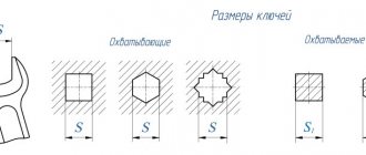
Areas of application for countersinks
Countersinking and countersinking, despite the fact that they are used for processing pre-prepared holes, have a number of fundamental differences.
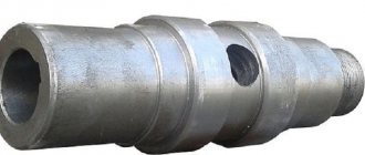
The main purpose of countersinking is to form conical or cylindrical recesses in the upper part of a pre-prepared hole, which are necessary to hide the heads of the fasteners used. Conical countersink with Morse shank type 8, cutting part material - HSS steel (analogous to P6M5)
Based on the degree of cleanliness of the recess formed during the countersinking process, such a technological operation is classified as semi-finishing. As a rule, it is performed before drilling holes in workpieces made of various materials. The equipment used for countersinking can be drilling, turning, milling and boring machines. A distinctive feature of this technological operation is that it is performed at low speeds, performed by a countersink or the workpiece being processed.
Types and application of countersinks
When processing parts on drilling and lathes, metal countersinking is used for:
- Formation of conical or cylindrical recesses of the required length in pre-prepared holes.
- Formation of reference planes near the holes.
- Removing chamfers in holes.
- Processing holes for fasteners.
You can often come across the term “counterbore”, which is the name of a tool designed for drilling out cylindrical recesses and supporting planes.
According to the configuration of the cutting part, the following types of countersinks are found:
- Cylindrical configuration.
- Conical countersinks.
- Face tools.
Based on the diameter of the machined holes, countersinks are divided into:
- Simple (from 0.5 to 1.5 mm).
- For holes with diameters from 0.5 to 6 mm. Available with or without safety cone.
- Countersinks with a tapered shank. Used for holes with a diameter of 8 to 12 mm.
Types of Hole Making Tools
GOST 14953-80.
conical countersinks. technical specifications (with changes n 1, 2) Both the countersink and the countersink in their geometric parameters must comply with the requirements indicated by the corresponding GOST or Technical Specifications (TU). The working part of the countersink consists of many cutting blades. It is used to process holes previously obtained by drilling. Depending on the design and scope of application, the following types of countersinks are distinguished.
- Cylindrical tools, the working part of which is coated with a wear-resistant material. Countersinks of this type, the requirements for which are regulated by GOST 12489-71, are produced with diameters from 10 to 20 mm.
- Solid countersinks of conical type, produced in the diameter range of 10–40 mm. The material for the manufacture of these tools, the characteristics of which must meet the requirements of TU 2-035-923-83, can be alloyed high-speed steel, as well as tool steel alloys. At the same time, a wear-resistant coating is applied to the working surface of such a countersink. Tools belonging to this category can be used for machining holes made in steel and cast iron parts.
- Countersinks are of one-piece mounted type, the diameter of which can be in the range of 32–80 mm. They are manufactured in accordance with the requirements established by GOST 12489-71.
- Conical countersinks, which can be of two types: type 1, produced in accordance with GOST 3231-71, and type 2 - a mounted countersink, the requirements for the characteristics of which are regulated by the provisions of the same regulatory document. The two types of countersinks differ only in the presence of plates on their working part, which are made of carbide material.
Countersink with guide pin
A countersink also belongs to the category of multi-blade cutting tools, but it is distinguished from a countersink by a list of technological tasks that can be solved with its help. In particular, using it, you can make recesses in pre-made holes, form chamfers on their surface, etc. The following types of countersinks are distinguished depending on their design.
- Conical countersinks, the working surface of which can be manufactured with angles of 60, 90 and 120°. The production of such countersinks is regulated by GOST 14953-80E, and they are used for processing holes for fasteners, metal products, as well as for removing internal chamfers.
- Countersinks are cylindrical type, which can be produced with a conical or cylindrical shank, as well as with a wear-resistant coating on the working surface. The regulatory document, the provisions of which regulate the requirements for the characteristics of cylindrical countersinks, is GOST 2I22-2-80. Using such a tool, support-type surfaces are usually processed.
Classification of countersinks and countersinks
The main purposes of the countersink include:
- preparing the surface of holes before cutting threads;
- calibration of holes for subsequent use of studs, bolts or other fasteners.
Metal countersink design
The countersinking operation allows you to increase the surface quality of holes up to 11, in some cases up to 9 quality. This level of processing precision corresponds to a roughness of 2.5 micrometers. In this case, all defects inherent in previous operations are eliminated: stamping, casting, drilling.
All countersinks and countersinks are made from high-speed steel. Usually alloy steel (40X) or carbon steel (St45) is used for them. To achieve a high level of smoothing and leveling (cleaning) of the hole surface, countersinks have several cutting edges.
Countersink
Countersinks are classified according to the following parameters:
- processing accuracy;
- type of construction;
- shape and number of cutting edges;
- grade of steel from which the tool is made.
According to processing accuracy, all countersinks are divided into two categories:
- metal countersink No. 1 (used for preparatory processing of holes before surgery, the so-called reaming);
- metal countersink No. 2 (used for final processing, allows you to obtain an accuracy grade of 11).
They are divided according to the type of construction:
- solid, with a tapered shank;
- solid mounted;
- solid tail;
- with carbide inserts (type 1);
- mounted with hard alloy plates (type 2);
- prefabricated tails with inserted knives;
- mounted assemblies.
In terms of length and diameter, a countersink is an analogue of a twist drill. Its working part consists of two components: a cutting part and a calibrating part. The length of the first part (cutting) depends on the required depth of countersinking. The second part (calibrating) consists of guides along the cutting edge. Their width depends on the diameter of the hole being processed, that is, on the diameter of the countersink and ranges from 0.8 to 2.5 millimeters. Its height for a standard countersink does not exceed 0.9 millimeters.
Conical countersinks for metal
A separate processing element is countersinking. Their similarity in name leads to a certain confusion in understanding the essence of these completely different operations. During the countersinking process, the surface of the prepared hole is processed to its entire depth. Countersinking for metal involves processing only the upper part of the hole. Thus, recesses are formed for the countersunk heads of hardware (screws, bolts, studs, rivets). Structurally, a countersink differs from a countersink in the shape of the working part. It has cutting teeth at the end along with guide pins. According to the shape of the cutting part itself, countersinks are made in three types: conical, cylindrical and end-face (also called counterbores).
Types of countersinks and countersinks:
- Cylindrical, with a diameter from 10 to 20 mm. Blades coated with wear-resistant materials GOST 12489-71.
- Indivisible conical from 10 to 40 mm. Made from alloy steel.
- Whole in the form of nozzles with a diameter from 32 to 80 mm.
- Conical with special plates made of hard iron alloy.
- Conical with a cone angle of 60, 90, 120 degrees. For applying chamfers for fasteners.
- Rounded countersink (cylindrical)
GOST 14953-80 S. 13
| Type 4 |
| Crap. 4 |
GOST R 53664-2009. high-strength cylindrical and conical bolts for bridge construction. nuts and washers for them. technical specifications
mm
| Table 4 |
| Types 5, 6, 7 |
| Crap. 5 |
| Dimensions in mm Table 5 |
| * Size on small diameter. |
| Types 8, 9, 10, 11 |
| teeth-Z |
| Dimensions in mm Table 6 |
| GOST 14953-80 S. 15 |
Countersink designation | Applicability | D | d | L |
| 2353-0083 | 5,0 | 2,00 | 45 | 3,0 |
| 2353-0084 | 6,3 | 2,50 | 50 | 3,7 |
| 2353-0085 | 8,0 | 3,15 | 4,7 | |
| 2353-0086 | 10,0 | 4,00 | 56 | 6,0 |
| 2353-0087 | 12,5 | 5,00 | 63 | 7,4 |
| 2353-0088 | 16,0 | 6,30 | 71 | 9,5 |
An example of a symbol for a countersink type 2, diameter D = 5 mm:
Countersink 2353-0083 GOST 14953-80 Type 3
Countersink designation | Applicability | d | D | D\ | L |
| 2357-0001 | 0,80 | 5,0 | 1,55 | 35,5 | 0,82 |
| 2357-0002 | 1,00 | 6,3 | 2,00 | 1,13 | |
| 2357-0003 | 1,25 | 7,1 | 2,40 | 40,0 | 1,21 |
| 2357-0004 | 1,60 | 8,0 | 3,10 | 45,0 | 1,52 |
| 2357-0005 | 2,00 | 10,0 | 4,00 | 2,20 | |
| 2357-0006 | 2,50 | 12,5 | 5,00 | 50,0 | 2,60 |
| 2357-0007 | 3,15 | 14,0 | 6,40 | 3,30 | |
| 2357-0008 | 4,00 | 16,0 | 7,90 | 56,0 | 4,20 |
| 2357-0009 | 5,00 | 20,0 | 10,00 | 63,0 | 5,20 |
| 2357-0010 | 6,30 | 25,0 | 12,50 | 71,0 | 6,50 |
An example of a symbol for a countersink type 3, diameter D = 5 mm:
Countersink 2357-0001 GOST 14953-80
| Type 4 |
| mm Table 4 |
| An example of a symbol for a countersink type 4, diameter D = 6.3 mm: Countersink 2353-0089 GOST 14953-80 |
| Table 5 mm |
| Continuation of the table. 5 |
| An example of a symbol for a countersink type 6, diameter D - 10 mm: Countersink 2353-0108 GOST 14953-80 |
| Dimensions, mm Table 6 |
GOST 14953-80 S. 11
APPENDIX 1 Recommended
CONSTRUCTION DIMENSIONS AND GEOMETRICAL PARAMETERS OF COUNTERSOCKERS
1. The design dimensions and geometric parameters of the countersinks must correspond to those indicated in the drawing. 1-6 and in table. 1-6.
| Type 1 |
| Crap. 1 |
| A~A |
| Table 1 | ||||||
mm
|
TECHNICAL REQUIREMENTS
GOST R 53664-2009 high-strength cylindrical and conical bolts for bridge construction. nuts and washers for them. technical specifications
2.1. (Deleted, Amendment No. 2). 2.2. Countersinks must be made from high-speed steel in accordance with GOST 19265. It is allowed to manufacture countersinks from other grades of high-speed steel, ensuring the performance and durability of countersinks are not inferior to countersinks made from high-speed steel in accordance with GOST 19265. By agreement with the consumer, it is allowed to manufacture countersinks from tool alloy steel grade 9ХС according to GOST 5950.
2.3. Countersinks made of high-speed steel with a cylindrical shank with diameters from 8 to 16 mm should be made in one piece, with diameters of 20 and 25 mm - welded. High-speed steel countersinks with a conical shank must be manufactured welded.
The following are not allowed in the welding zone: lack of penetration, ring cracks, surface holes.
It is allowed to manufacture soldered countersinks with cylindrical and conical shanks with diameters from 12.5 to 25 mm.
Brass grade L63 according to GOST 15527 should be used as solder.
2.4. The shanks of welded and brazed countersinks must be made of steel grade 45 according to GOST 1050 or grade 40X according to GOST 4543.
2.5. The hardness of the working part of the countersinks should be:
for countersinks made of high-speed steel with a diameter of up to 3.15 mm - 63 ... 65 HRC3, over 3.15 mm - 63 ... 66 HRC3;
for countersinks made of steel grade 9ХС - 62 ... 65 HRC3.
The hardness of the working part of countersinks made of high-speed steel with a vanadium content of 3% or more and cobalt of 5% or more should be higher by 1-2 HRC3 units.
2.6. The hardness of the feet for countersinks with a conical shank should be 32 ... 47 HRC3.
2.7. The surface of the countersinks should not have cracks or signs of corrosion. Sanded surfaces should not have dents or rough spots. There should be no tarnish on the front and back surfaces, on the surfaces of the ribbons and the shank. Cutting edges must be sharp; debris and chipped areas on cutting edges are not allowed.
(Changed edition, Amendment No. 1, 2).
2.8. The roughness parameters of countersink surfaces according to GOST 2789 should be, microns, no more than:
front and rear surfaces of countersinks types:
1-4……………………………………………………………..Rz 6.3
5-11……………………………………………………………………..DgZ,2
surfaces of chip flutes……………………………….Rz 10
surface of the clamping cylindrical part, cylindrical and conical
shank…………………………………………………………..Ra 0.8
other surfaces……………………………………..Rz 20
2.9. On the back surface of the teeth of countersinks of types 5-11 along the main cutting edges, a ribbon with a width of no more than 0.05 mm is allowed.
2.10. Maximum deviations of countersink dimensions should be no more than:
total length L…………………………………………Б6
diameter of the clamping cylindrical part…………………………b9
cone angles 60° and 75°……………………………………………………….—20′
cone angles 90° and 120°………………………………………………………—G
length of cylindrical shank……………………………..±1 mm
2.11. The runout tolerance of the cutting edges of the countersink part for countersinks of types 1-4 relative to the surface of the clamping part, measured perpendicular to these edges, should be for countersinks with a diameter of:
up to 3.15 mm…………………………………………….0.03 mm
St. 3.15 mm………………………………………………………………0.04 mm
2.12. The runout tolerance of the cutting edges of countersinks of types 5-11 relative to the surface of the shank, measured perpendicular to these edges, should be 0.05 mm.
2.13. The average and established periods of resistance of countersinks must be no less than those indicated in the table. 7 subject to the tests given in Section. 4.
which should not be more than 0.6 mm for countersinks types 1-4 and 0.8 mm for countersinks types 5-11.
| Table 7 |
| 2.14. The criterion for dullness should be considered the achievement of wear on the rear surface, |
LABELING, PACKAGING, TRANSPORTATION AND STORAGE
5.1. The following must be clearly marked on the neck, shank or holder of the countersink:
a) trademark of the manufacturer;
b) diameter for countersinks types 2-4 or diameter for countersinks types 1.5-11;
c) countersink cone angle;
d) countersink designation (last four digits);
e) steel grade of the cutting part (on countersinks made of high-speed steel). Notes: 1. On countersinks of types 1-4 with a diameter of 5 to 8 mm and types 5-7 with a diameter of 8 to 12.5 mm, it is allowed to mark only the data specified in subparagraphs a, b, c.
2. Marking on the shanks or holders of countersinks may be applied by electrochemical, chemical or other methods that do not affect the quality of the surface and provided that their geometric shapes are preserved, as well as in the recess for marking.
3. (Deleted, Amendment No. 1).
4. Steel grade R6M5 and R6AM5 may not be marked.
5. Instead of the high-speed steel grade, it is allowed to mark the letters “HS” for steel with a tungsten content up to 3% inclusive, the letters “HSS” for steel with a tungsten content of 6% or more, the letters “HSSCo” for steel containing cobalt, with an indication steel grades on labels.
5.2. The option for internal packaging of countersinks is VU-1 according to GOST 9.014.
5.1, 5.2. (Changed edition, Amendment No. 1, 2).
5.3. Other requirements for packaging, labeling, transportation and storage are in accordance with GOST 18088. (Introduced additionally, Amendment No. 1). Section 6. (Deleted, Amendment No. 1).
TEST METHODS
4.1. Tests of countersinks must be carried out on centering, lathe or drilling machines using chucks and collets that meet the accuracy standards established for them.
4.2. Countersinks must be tested on samples made of steel grades 45 or 50 according to GOST 1050, hardness HB 179...197 using pre-drilled holes corresponding to GOST 14034 and GOST 12876 for countersinks of types 6 and 10.
4.3. Resistance tests are carried out on countersinks with a diameter of 8 mm for type 1; 6.3 mm for types 2-4, 20 mm for types 5-11. It is allowed to additionally test countersinks of other standard sizes from those regulated by the standard.
4.1-4.3. (Changed edition, Amendment No. 1).
4.3.1. Tests should be carried out at the modes indicated in Table 8.
Table 8
| Countersink type | Diameter, mm | Feed, mm/rev | Speed, m/min | |
| external countersink | center hole | |||
| 1 | 5,0 | — | 0,05 | 14 |
| 8,0 | 0,08 | 16 | ||
| 2-4 | — | 0,8 | 0,01 | 8 |
| 1,0 | 10 | |||
| 1,25 | ||||
| 1,6 | 0,02 | |||
| 2,0 | 12 | |||
| 2,5 | 0,03 | |||
| 3,15 | ||||
| 2-4 | — | 4,0 | 0,04 | 14 |
| 5,0 | 0,05 | |||
| 6,3 | 0,06 | |||
| 8,0 | 0,08 | 16 | ||
| 5-11 | 8,0 | — | 0,06 | 12 |
| 10,0 | ||||
| 12,5 | 14 | |||
| 16,0 | 0,08 | |||
| 20,0 | 16 | |||
| 25,0 | 0,10 | |||
| 31,5 | ||||
| 40,0 | 18 | |||
| 50,0 | 0,12 | |||
| 63,0 | ||||
| 80,0 | 0,14 |
Notes:
1. The rotation speed for countersinks of types 1-4 is determined by the diameter of the machined hole, and for countersinks of types 5-11 - by the largest diameter of the countersinked hole. For countersinks of types 7 and 11, the hole must be pre-countersunked.
2. When testing countersinks made of 9ХС steel, the cutting speed is assumed to be equal to 0.6 of the cutting speed of countersinks made of high-speed steel. (Introduced additionally, Amendment No. 1).
4.4. Acceptance values of the average and established durability periods should not be less than those indicated in Table 9.
Table 9
| Countersink type | Countersink outer diameter, mm | Acceptance values of durability periods, min | |
| average | installed | ||
| 1 | 5,0 | 23 | 9 |
| 8,0 | |||
| 2 | 5,0 | 23 | 9 |
| 6,3; 8,0; 10,0 | 34 | 14 | |
| 12,5; 16,0 | 68 | 27 | |
| 3 | 5,0; 6,3 | 23 | 9 |
| 7,1; 8,0; 10,0 | 34 | 14 | |
| 12,5; 14,0; 16,0; 20,0; 25,0 | 68 | 27 | |
| 4 | 6,3 | 23 | 9 |
| 8,0 | 34 | 14 | |
| 5, 8 and 9 | 8,0 | 23 | 9 |
| 10,0 | 28 | 11 | |
| 12,5 | 34 | 14 | |
| 16,0 | 34 | 14 | |
| 20,0 | 57 | 23 | |
| 25,0 | 79 | 32 | |
| 31,5 | 113 | 45 | |
| 40,0 | 147 | 59 | |
| 50,0 | 181 | 72 | |
| 63,0 | 204 | 81 | |
| 80,0 | 204 | 81 | |
| 6, 7, 10 and 11 | 8,0 | 11 | 5 |
| 10,0 | 14 | 5,4 | |
| 12,5 | 17 | 7 | |
| 16,0 | 17 | 7 | |
| 20,0 | 23 | 9 | |
| 25,0 | 34 | 14 | |
| 31,5 | 51 | 20 | |
| 40,0 | 51 | 20 | |
| 50,0 | 68 | 27 | |
| 63,0 | 90 | 36 | |
| 80,0 | 90 | 36 |
4.5. When testing for performance, three holes must be machined with each working end of the countersink for the length of the conical part of the countersink, and for countersinks of types 2-4 - five holes.
4.6. A 5% solution of emulsol in water with a flow rate of at least 5 l/min should be used as a cutting fluid.
4.7. After performance testing, the cutting edges of the countersinks should be free of dents and chipping and should be suitable for further work.
4.4-4.7. (Changed edition, Rev. 1, 2).
4.8. Appearance control is carried out visually.
4.9. Control of countersink parameters is carried out by means of control, the error of which should not be more than: when measuring linear dimensions - the values specified in GOST 8.051; when measuring angles - 35% of the tolerance values for the angle being tested; when monitoring the shape and location of surfaces - 25% of the tolerance values for the parameter being tested.
4.10. The hardness of countersinks is measured according to GOST 9013.
4.11. The surface roughness parameters of countersinks should be checked by comparison with roughness samples in accordance with GOST 9378 or with standard tools having values of surface roughness parameters not exceeding those specified in clause 2.8. Comparison is carried out visually using a magnifying glass 2-4 in accordance with GOST 25706.
4.8-4.11. (Introduced additionally, Amendment No. 1).
Countersinking
The work is performed on lathes (to produce holes from the end side), drilling, CNC milling and boring machines (to change the size of the hole). The selection of tools is made based on the location of the hole and material, the depth and size of the hole, and the method of fastening. The processing speed in countersinking is identical to the drilling speed. For light steel, the angle of inclination is 15-20 degrees, for medium-light alloys - 8-10 degrees. High-alloy steels and cast iron are processed at an angle of 0-5 degrees, according to GOST 12479-71.
The use of automatic equipment allows us to achieve high precision of the processed surface. When performing work, you must adhere to the following safety rules: the surface of the countersink must be well sharpened and free of burrs and cracks
When attaching the shank, you need to pay attention to the smoothness of the surface as fasteners.
APPENDIX 1 (recommended). CONSTRUCTION DIMENSIONS AND GEOMETRICAL PARAMETERS OF COUNTERSOCKERS
APPENDIX 1 Recommended
1. The design dimensions and geometric parameters of the countersinks must correspond to those indicated in Figures 1-6 and Tables 1-6.
Type 1
Damn.1
Table 1
mm
| 5 | 4 | 0,3 |
| 8 | 6 | 0,5 |
Damn.2. Type 2
Type 2
Damn.2
table 2
mm
| Nom. | Prev. off | Nom. | Prev. off | ||||
| 5,0 | 1,5 | -0,12 | 10 | 0,40 | +0,03-0,06 | 0,4 | 0,3 |
| 6,3 | 2,0 | 11 | 0,45 | 0,7 | 0,5 | ||
| 8,0 | 2,6 | 13 | 0,55 | ||||
| 10,0 | 3,0 | 15 | 0,70 | +0,04-0,08 | 0,8 | 0,8 | |
| 12,5 | 4,0 | -0,16 | 17 | 0,85 | 1,0 | ||
| 16,0 | 5,0 | 19 | 1,10 | 1,2 |
Damn.3. Type 3
Type 3
Damn.3
Table 3
mm
| Nom. | Prev. off | Nom. | Prev. off | Nom. | Prev. off | ||||
| 5,0 | 1,55 | +0,2 | 0,60 | -0,06 | 8 | 0,15 | +0,02-0,04 | 0,3 | 0,2 |
| 6,3 | 2,00 | +0,3 | 0,70 | -0,07 | 9 | 0,20 | +0,03-0,06 | 0,3 | |
| 7,1 | 2,40 | +0,4 | 1,00 | -0,12 | 0,25 | ||||
| 8,0 | 3,10 | 1,35 | 11 | 0,30 | 0,4 | ||||
| 10,0 | 4,00 | +0,6 | 1,50 | 13 | 0,40 | ||||
| 12,5 | 5,00 | 2,00 | 15 | 0,45 | 0,7 | 0,5 | |||
| 14,0 | 6,40 | 2,60 | 16 | 0,55 | |||||
| 16,0 | 7,90 | +1,0 | 3,00 | 18 | 0,70 | +0,04-0,08 | 0,8 | 0,8 | |
| 20,0 | 10,00 | 4,00 | -0,16 | 19 | 0,85 | 1,0 | |||
| 25,0 | 12,50 | +1,5 | 5,00 | 22 | 1,10 | 1,2 |
Type 4
Damn.4
Table 4
mm
| -0,12 | +0,03-0,06 | ||||
| 6,3 | 1,5 | 11 | 0,40 | 0,4 | 0,3 |
| 8,0 | 2,0 | 12 | 0,45 | 0,7 | 0,5 |
Damn.5. Types 5, 6, 7
Types 5, 6, 7
Damn.5
Table 5
Dimensions in mm
| * | Number of teeth | ||||||||||
| Type 5 | Types 6, 7 | Type 5 | Type 6 | Type 7 | Type 5 | Type 6 | Type 7 | ||||
| 8,0 | — | — | 0,3 | 0,5 | 90° | 90° | 90° | 15° | 26°20′ | 38°30′ | 4 |
| 10,0 | 0,4 | 0,6 | 16° | 27° | 40° | ||||||
| 12,5 | 0,85 | 17°35′ | 25° | 36°20′ | |||||||
| 16,0 | 0,6 | 1,00 | 18°26′ | 22° | 32°20′ | ||||||
| 20,0 | 36 | 32 | — | 80° | 80° | 80° | 18°55′ | 30°41′ | 41°50′ | 6 | |
| 25,0 | 41 | 37 | 85° | 85° | 85° | 19°45′ | 32°20′ | 43° |
_______________* Size on small diameter.
Damn.6. Types 8, 9, 10, 11
Types 8, 9, 10, 11
Damn.6
Table 6
Dimensions in mm
| * | |||||||||||
| Type 8 | Type 9 | Types 10, 11 | Type 8 | Type 9 | Type 10 | Type 11 | Types 8, 9, 10, 11 | ||||
| 16,0 | 32 | — | 30 | — | — | — | — | 70 | 0,6 | 14 | 1,0 |
| 20,0 | 85 | 20 | — | ||||||||
| 25,0 | 36 | 32 | 22 | ||||||||
| 31,5 | 43 | 50 | 35 | 11 | 8 | 4 | 3,5 | ||||
| 40,0 | 50 | 60 | 40 | 17 | 10 | 6 | 4,0 | 105 | 1,0 | 35 | |
| 50,0 | 55 | — | 43 | — | 8 | 5,0 | 1,5 | 40 | |||
| 63,0 | 64 | 65 | 50 | 10 | 10 | 7,0 | 130 | 1,8 | |||
| 80,0 | 80 | — | 60 | 18 | — | 12 | 8,0 | 60 |
Continuation of Table 6
Dimensions in mm
| Type 8 | Type 9 | Types 10, 11 | Type 8 | Type 9 | Type 10 | Type 11 | Types 8,10 | Type 9 | Type 11 | |
| 16,0 | 90° | — | 90° | 18°26′ | — | 22° | 32°20′ | 4 | — | 4 |
| 20,0 | 80° | 80° | 18°55′ | 30°41′ | 41°50′ | 6 | 6 | |||
| 25,0 | 85° | 85° | 19°45′ | 32°20′ | 43° | |||||
| 31,5 | 80° | 80° | 80° | 20°24′ | 27°00′ | 32°47′ | 45° | 8 | 8 | 8 |
| 40,0 | 21°26′ | 28°20′ | 34°12′ | 46°30′ | ||||||
| 50,0 | — | 22° | — | 34°59′ | 45°40′ | — | ||||
| 63,0 | 80° | 23°07′ | 28°30′ | 36°30′ | 48° | 8 | ||||
| 80,0 | — | 23°54′ | — | 37°03′ | 48°30′ | 10 | — | 10 |
_____________* Size on small diameter. (Changed edition, Amendment No. 1).
2. For countersinks of types 1-4, the clearance angle at the periphery of the cutting part in a plane parallel to the axis of the countersink is 14-11°. APPENDIX 2. (Deleted, Amendment No. 1). Library of GOSTs and regulatory documents
GOST 14953-80 S. 5
An example of a symbol for a countersink type 8, diameter D = 16 mm:
Countersink 2353-0121 GOST 14953-80
(Changed edition, Amendment No. 1).
1.3. Dimensions of Morse cones - according to GOST 25557. Tolerance of Morse cones AT8 - according to GOST 2848.
1.4. Center holes of form A (form R is allowed) in accordance with GOST 14034; for countersinks with d0 < 7 mm, center holes should not be made on the side of the working part.
1.5. The design dimensions and geometric parameters of the countersinks are indicated in Appendix 1.
| Continuation of the table. 6 |
| * For type 9. |
Areas of application for countersinks
Countersinking and countersinking, despite the fact that they are used for processing pre-prepared holes, have a number of fundamental differences. The main purpose of countersinking is to form conical or cylindrical recesses in the upper part of a pre-prepared hole, which are necessary to hide the heads of the fasteners used.
Conical countersink with Morse shank type 8, cutting part material - HSS steel (analogous to P6M5)
Based on the degree of cleanliness of the recess formed during the countersinking process, such a technological operation is classified as semi-finishing. As a rule, it is performed before drilling holes in workpieces made of various materials. The equipment used for countersinking can be drilling, turning, milling and boring machines. A distinctive feature of this technological operation is that it is performed at low speeds, performed by a countersink or the workpiece being processed.
According to their design, countersinks are distinguished:
- conical (GOST 14953-80);
- cylindrical type.
Types of Conical Countersinks
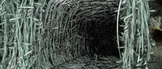
A separate category of countersinks consists of cutters, which are made of carbide materials and are used primarily for grinding and roughing work. Another type of countersinks that are used for machining and chamfering holes located in hard-to-reach places are reverse-type tools. Specialists who often work with countersinks of this type prefer to have at their disposal entire sets of them, which allow them to process holes with various geometric parameters.
Roller cutter is a type of countersink used for cutting valves of an internal combustion engine
Conical countersinks produced in accordance with GOST 14953-80 have a standard design, the constituent elements of which are a shank and a working part with a front end sharpened to a cone. The cone angle, which is formed by the side surfaces of the front part of such a countersink, can be 60, 75, 90 or 120°. GOST 14953-80 also regulates the number of teeth on the working part, which depends on its diameter.
Thus, countersinks of various diameters (12–60 mm) may contain from six to twelve cutting teeth. Depending on the length of the tool used for processing, which is also regulated by the provisions of the regulatory document, a trunnion can be used to support it on the machine, ensuring the alignment of the surface being formed.
Types of Standard Conical Countersinks
Cylindrical countersinks, in contrast to conical tools (manufactured according to the requirements specified by GOST 14953-80), are specifically used for cutting chamfers for metal products. The working part of such a countersink, which usually has a wear-resistant coating, resembles a drill, but differs from it in a large number of cutting teeth. Depending on the diameter of the working part, it can have from 4 to 10 cutting teeth. To reliably fix the position of such a tool during its operation, there is a special guide pin at its end - solid or removable. The most convenient and practical to use are countersinks with removable trunnions. In addition, for greater efficiency of the processing performed, an additional cutting attachment can be installed on the countersink.
In order to process several holes to the same depth using one countersink, the tool is equipped with a special holder with a limiter, which can be stationary or rotating. In this case, the cutting tool is mounted in a holder, and its working part protrudes from its stop by an amount equal to the depth of the hole being machined.
These chamfers on the holes were made with a conical countersink
Various metals and alloys can be used as materials for the manufacture of countersinks, in particular:
- ;
- alloyed high-speed steel alloys;
- carbide materials.
For processing holes made in soft metals, as well as in materials such as wood or plastic, countersinks made of steel alloys are used. If it is necessary to process holes made in products made of harder metals, then carbide countersinks are used for this. The latter are able to withstand significant loads arising when processing metals with high hardness.
Design
The conical countersink consists of two main elements - the working part and the shank. The working part has a cone with a standard range of angles at the apex from 60 to 120°. The number of cutting blades depends on the diameter of the tool and can be from 6 to 12 pieces.
A cylindrical countersink is similar in design to a drill, but has more cutting elements. At the end there is a guide pin necessary for fixing the position of the tool during processing. The limiter can be removable or be part of the body of the instrument. The first option is more practical, as it expands processing capabilities. A cutting attachment can also be installed.
If it is necessary to drill several holes to equal depths, a tool with holders with a rotating or fixed stop is used. Before processing, the countersink is fixed in the holder so that the cutting part protrudes from the stop at a distance equal to the required depth of hole processing.
The tool is made from tool alloy, carbon, high-speed and carbide steel grades. For processing cast iron parts, carbide steels are most often used; for ordinary steels, high-speed and tool steels are used.
GOST 14953-80 S. 13
| Type 4 |
| Crap. 4 |
mm
| Table 4 |
| Types 5, 6, 7 |
| Crap. 5 |
| Dimensions in mm Table 5 |
| * Size on small diameter. |
| Types 8, 9, 10, 11 |
| teeth-Z |
| Dimensions in mm Table 6 |
| GOST 14953-80 S. 15 |
Countersink designation | Applicability | D | d | L |
| 2353-0083 | 5,0 | 2,00 | 45 | 3,0 |
| 2353-0084 | 6,3 | 2,50 | 50 | 3,7 |
| 2353-0085 | 8,0 | 3,15 | 4,7 | |
| 2353-0086 | 10,0 | 4,00 | 56 | 6,0 |
| 2353-0087 | 12,5 | 5,00 | 63 | 7,4 |
| 2353-0088 | 16,0 | 6,30 | 71 | 9,5 |
An example of a symbol for a countersink type 2, diameter D = 5 mm:
Countersink 2353-0083 GOST 14953-80 Type 3
Countersink designation | Applicability | d | D | D\ | L |
| 2357-0001 | 0,80 | 5,0 | 1,55 | 35,5 | 0,82 |
| 2357-0002 | 1,00 | 6,3 | 2,00 | 1,13 | |
| 2357-0003 | 1,25 | 7,1 | 2,40 | 40,0 | 1,21 |
| 2357-0004 | 1,60 | 8,0 | 3,10 | 45,0 | 1,52 |
| 2357-0005 | 2,00 | 10,0 | 4,00 | 2,20 | |
| 2357-0006 | 2,50 | 12,5 | 5,00 | 50,0 | 2,60 |
| 2357-0007 | 3,15 | 14,0 | 6,40 | 3,30 | |
| 2357-0008 | 4,00 | 16,0 | 7,90 | 56,0 | 4,20 |
| 2357-0009 | 5,00 | 20,0 | 10,00 | 63,0 | 5,20 |
| 2357-0010 | 6,30 | 25,0 | 12,50 | 71,0 | 6,50 |
An example of a symbol for a countersink type 3, diameter D = 5 mm:
Countersink 2357-0001 GOST 14953-80
| Type 4 |
| mm Table 4 |
| An example of a symbol for a countersink type 4, diameter D = 6.3 mm: Countersink 2353-0089 GOST 14953-80 |
| Table 5 mm |
| Continuation of the table. 5 |
| An example of a symbol for a countersink type 6, diameter D - 10 mm: Countersink 2353-0108 GOST 14953-80 |
| Dimensions, mm Table 6 |
TYPES AND MAIN SIZES
1. TYPES AND MAIN DIMENSIONS
The purpose of the countersink tool and its differences from the counterbore
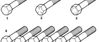
1.1. Conical countersinks must be made of the following types:
1 — countersinks with an apex angle of 60° centering;
2 - centering countersinks for center holes with an apex angle of 60° without a safety cone;
3 - centering countersinks for center holes with an apex angle of 60° with a safety cone of 120°;
4 - centering countersinks for center holes with an apex angle of 75° without a safety cone;
5 - countersinks with an apex angle of 60° with a cylindrical shank;
6 — countersinks with an apex angle of 90° with a cylindrical shank;
7 — countersinks with an apex angle of 120° with a cylindrical shank;
8 — countersinks with an apex angle of 60° with a conical shank;
- GOST 6713-91. low-alloy structural steel for bridge construction. technical specifications
9 — countersinks with an apex angle of 75° with a conical shank;
10 — countersinks with an apex angle of 90° with a conical shank;
11 - countersinks with an apex angle of 120° with a conical shank.
1.2. The main dimensions of the countersinks must correspond to those indicated in Figures 1-6 and in Tables 1-6.
Damn.1. Type 1
Type 1
Damn.1
Table 1
mm
| Countersink designation | Applicability | ||
| 2353-0081 | 5 | 50 | 10 |
| 2353-0082 | 8 | 60 | 12 |
An example of a symbol for a countersink type 1, diameter = 5 mm:
GOST 24379.0-2012 foundation bolts. general technical conditions
Countersink 2353-0081 GOST 14953-80
Damn.2. Type 2
Type 2
Damn.2
table 2
mm
| Countersink designation | Applicability | |||
| 2353-0083 | 5,0 | 2,00 | 45 | 3,0 |
| 2353-0084 | 6,3 | 2,50 | 50 | 3,7 |
| 2353-0085 | 8,0 | 3,15 | 4,7 | |
| 2353-0086 | 10,0 | 4,00 | 56 | 6,0 |
| 2353-0087 | 12,5 | 5,00 | 63 | 7,4 |
| 2353-0088 | 16,0 | 6,30 | 71 | 9,5 |
An example of a symbol for a countersink type 2, diameter = 5 mm:
Countersink 2353-0083 GOST 14953-80
Damn.1. Type 3
Type 3
Damn.3
Table 3
mm
| Countersink designation | Applicability | ||||
| 2357-0001 | 0,80 | 5,0 | 1,55 | 35,5 | 0,82 |
| 2357-0002 | 1,00 | 6,3 | 2,00 | 1,13 | |
| 2357-0003 | 1,25 | 7,1 | 2,40 | 40,0 | 1,21 |
| 2357-0004 | 1,60 | 8,0 | 3,10 | 45,0 | 1,52 |
| 2357-0005 | 2,00 | 10,0 | 4,00 | 2,20 | |
| 2357-0006 | 2,50 | 12,5 | 5,00 | 50,0 | 2,60 |
| 2357-0007 | 3,15 | 14,0 | 6,40 | 3,30 | |
| 2357-0008 | 4,00 | 16,0 | 7,90 | 56,0 | 4,20 |
| 2357-0009 | 5,00 | 20,0 | 10,00 | 63,0 | 5,20 |
| 2357-0010 | 6,30 | 25,0 | 12,50 | 71,0 | 6,50 |
An example of a symbol for a countersink type 3, diameter = 5 mm:
Countersink 2357-0001 GOST 14953-80
Damn.4. Type 4
Type 4
Damn.4
Table 4
mm
| Countersink designation | Applicability | |||
| 2353-0089 | 6,3 | 45 | 2,0 | 3,1 |
| 2353-0090 | 8,0 | 50 | 2,5 | 3,9 |
An example of a symbol for a countersink type 4, diameter = 6.3 mm:
Countersink 2353-0089 GOST 14953-80
Damn.5. Types 5, 6, 7
Types 5, 6, 7
Damn.5
Table 5
mm
| Type 5 countersink designation | Applicability | Type 6 countersink designation | Applicability | Type 7 countersink designation | Applicability | ||
| Type 5 | Types 6, 7 | Type 5 | Types 6, 7 | ||||
| 2353-0101 | 8,0 | 1,6 | 8 | 48 | — | 16 | — |
| 2353-0107 | — | 44 | — | 12 | |||
| 2353-0114 | |||||||
| 2353-0102 | 10,0 | 2,0 | 50 | — | 18 | — | |
| 2353-0108 | — | 46 | — | 14 | |||
| 2353-0115 | |||||||
| 2353-0103 | 12,5 | 2,5 | 52 | — | 20 | — | |
| 2353-0109 | — | 48 | — | 16 | |||
| 2353-0116 | |||||||
| 2353-0104 | 16,0 | 3,2 | 10 | 60 | — | 24 | — |
| 2353-0111 | — | 56 | — | 20 | |||
| 2353-0117 | |||||||
| 2353-0105 | 20,0 | 4,0 | 64 | — | 28 | — | |
| 2353-0112 | — | 60 | — | 24 | |||
| 2353-0118 | |||||||
| 2353-0106 | 25,0 | 7,0 | 69 | — | 33 | — | |
| 2353-0113 | — | 65 | — | 29 | |||
| 2353-0119 |
An example of a symbol for a countersink type 6, diameter = 10 mm:
Countersink 2353-0108 GOST 14953-80
Damn.6. Types 8, 9, 10, 11
Types 8, 9, 10, 11
Damn.6
Table 6
Dimensions, mm
| Type 8 countersink designation | Applicability | Designation of countersink type 9 | Applicability | Designation of countersink type 10 | Applicability | Designation of countersink type 11 | Applicability | Morse cone | |
| Type 8 | Type 9 | Types 10, 11 | Type 8 | Type 9 | Types 10, 11 | ||||
| 2353-0121 | 16,0 | 3,2 | 97 | — | — | 24 | — | — | 1 |
| 2353-0133 | — | 93 | — | 20 | |||||
| 2353-0142 | |||||||||
| 2353-0122 | 20,0 | 4,0 | 120 | — | 28 | — | 2 | ||
| 2353-0134 | — | 116 | — | 24 | |||||
| 2353-0143 | |||||||||
| 2353-0123 | 25,0 | 7,0 | 125 | — | — | 33 | — | — | 2 |
| 2353-0135 | — | 121 | — | 29 | |||||
| 2353-0144 | |||||||||
| 2353-0124 | 31,5 | 9,0; 7,0* | 132 | — | — | 40 | — | — | |
| 2353-0129 | — | 127 | — | 35 | |||||
| 2353-0136 | — | 124 | — | 32 | |||||
| 2353-0145 | |||||||||
| 2353-0125 | 40,0 | 12,5; 11,0* | 160 | — | — | 45 | — | — | 3 |
| 2353-0131 | — | 155 | — | 40 | |||||
| 2353-0137 | — | 150 | — | 35 | |||||
| 2553-0146 | |||||||||
| 2353-0126 | 50,0 | 16,0 | 165 | — | — | 50 | — | — | |
| 2353-0138 | — | 153 | — | 38 | |||||
| 2353-0147 | |||||||||
| 2353-0127 | 63,0 | 20; 18,0* | 200 | — | — | 58 | — | — | 4 |
| 2353-0132 | — | 192 | — | 50 | |||||
| 2353-0139 | — | 185 | — | 43 | |||||
| 2353-0148 | |||||||||
| 2353-0128 | 80,0 | 25,0 | 215 | — | — | 73 | — | — | |
| 2353-0141 | — | 196 | — | 54 | |||||
| 2353-0149 |
______________* For type 9. Example of symbol for countersink type 8, diameter = 16 mm:
Countersink 2353-0121 GOST 14953-80
(Changed edition, Amendment No. 1).
1.3. Dimensions of Morse cones - according to GOST 25557. Tolerance of Morse cones AT8 - according to GOST 2848.
1.4. Center holes of form A (form R is allowed) in accordance with GOST 14034; for countersinks with 7 mm on the side of the working part, do not make center holes.
1.5. The design dimensions and geometric parameters of the countersinks are indicated in Appendix 1.