The level is one of the most used optical measuring instruments in the geodetic, manufacturing and construction industries. With their help, height differences between different points on earth surfaces or engineering structures are determined. For correct altitude measurements, it is important to have a working optical level. And therefore it is necessary to carry out periodic checks of these instruments.
During manufacture, optical levels must be checked at the manufacturing plants and notes about this are made in the device passport. This does not mean at all that level checks are not needed. On the contrary, if I may say so, for confidence in your partner, it is recommended to have the device checked by a metrological service. After this, surveyors will have to verify this themselves by personally performing the main verifications before using it.
Round level checks
In levels, and other geodetic instruments, field measurements are made, as a rule, relative to certain reference points. These can be considered plumb lines. So, the vertical level of the levels is controlled by a round level, or rather its air bubble, which must be in the center of the ampoule. Usually the body of the level is set in a position in which it will be located along two lifting screws. By rotating them, the bubble is placed in the middle of the round level ampoule in the direction of the third lifting screw. Then, using this screw, the vial is brought out to the center of the ampoule, periodically correcting its position with two other screws. This procedure is repeated until the bubble is established in a central position inside the level ampoule.
To check that the bubble will be in the center, turn the body of the level 180 degrees. The bubble will probably move off center and deviate beyond the circle line it should not move beyond. Then you need to visually determine the distance the bubble is displaced from the center. And remove half of its value by rotating the lifting screws. At the same time, depending on the direction of its displacement, choose which lifting screw to do this with. The second half of the bubble deflection value is corrected with adjusting screws. Then the verification is repeated until the bubble is in the center of the level.
How to use the level
First, the device must be configured so that it allows accurate marking.
Setting up the laser level
- Place the device on a level surface or secure it to a tripod.
- Perform horizontal leveling by rotating the screws of the bubble level. Some models have two or three levels built-in. But there are models with self-leveling. And if the level is uneven, a sound signal is given. Its absence indicates that the device is installed correctly. But this does not mean that the device can level itself. Here, too, you need to tighten the screws.
- If your level creates vertical and horizontal lines, then set it to emit both at the same time or turn off one of them.
- Some models have the ability to emit lines and dots, the shutdown of which is also regulated.
- Adjust the angle and rotation speed of the beam, if these functions are available.
- If the level can work with a laser beam receiver, then install it. Using a receiver allows you to double the range. If there is no such function, then buy a reflective plate. It increases the accuracy and range of measurements. It needs to be fixed to the object.
Disabling functions that are currently unnecessary allows you to increase the operating time of the device on batteries or on a single battery charge.
Working on the floor using a level
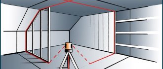
During construction, a laser level greatly facilitates the installation of floor joists at the same level.
- Turn on the device. The red line will show the zero level of the future floor.
- The laser level builds a line along the entire perimeter of the room. The result is a plane. Any size can be set aside from it.
- Install the logs along the laser lines.
- After installation, use a level to check the level. To do this, place the board with its side surface on the joist and direct the beam. Draw a line along it with a marker.
- Move the target to each lag. If they are installed horizontally, the laser beam will pass along the marker mark. If not, then the position of the log needs to be adjusted by raising and lowering it until the mark coincides with the laser line.
Video: Using a laser level for interior decoration
To check the evenness of poured concrete, place a pole anywhere in the room and mark on it the level that the red beam shows. Go through other points and compare the deviations of the marks.
Checking floor levelness with a laser level
Using a level, you can build straight and perpendicular lines on the floor to lay out the tiles evenly.
Laser level creates horizontal and perpendicular lines on the floor
- alignment of walls. This type of work demonstrates how outdated rulers and bubble levels are. Using a laser level, it is enough to direct the beam along the surface of the wall in any direction. Using a ruler, measure the deviation at different points of the beam;
- laying tiles. It is done similarly to work on the floor;
- construction of oblique lines. To do this, direct the beam at an angle. If this is not possible, tilt the level body. In laser levels with self-leveling mode, you need to block this function, otherwise it will interfere with work in an inclined position;
- posting decor in any room. Wallpaper and posters are aligned along the vertical beam. They make horizontal borders on the walls and hang decorative elements;
- installation of furniture, cornices, appliances. One crookedly hanging part of the interior spoils the overall impression of a beautiful room. Re-weighing using a ruler or angle takes much longer than using a laser level;
- redevelopment of premises. To install partitions, it is enough to point the beam at the installation site;
- use in measurements. You cannot measure distance with a level, but you can make the process easier. For example, if you need to find out the height of a room with non-vertical walls. You need to direct the beam upward and measure the distance between the floor and the ceiling.
Checking the mesh of threads
Consists of checking the geometric conditions of part of the optical system of the level. Its essence is that the condition of parallelism of the vertical grid, the axis of rotation of the level body and the plumb line is observed.
For all types of levels such verifications are carried out as follows. At a distance of about twenty-five meters from the level, a weighted cord plumb line is suspended. The device itself is naturally in working condition after the previous verification. The telescope of the level must be pointed towards the plumb line. Using the leveling screw, the vertical thread is precisely focused and aligned with the plumb line. Along the entire length of the lens it should coincide with the plumb line. If the thread grid is displaced by more than 0.5 millimeters, its position must be adjusted. The correction is made after unfastening the reticle screws located under the unscrewing cap in the area of the eyepiece part of the level. The top screws are loosened approximately one full turn, and any of the horizontal screws are loosened by half or three quarters of a turn of the screw. After which, the entire frame of the mesh of threads is carefully rotated in the direction of verticality, which is visually checked through the eyepiece. The fastening screws are tightened in the reverse order, and the alignment of the vertical thread with the line of the plumb line is finally observed in the eyepiece. Once the mesh of threads has reached verticality, the protective cap is screwed into place.
Adjusting the level and checking the functionality of the compensator
Contents: Highlights of the adjustment Checking the functionality of the tool compensator The process of level adjustment is carried out after the identification and verification of the tool and its probable deviations. This procedure is required to correct inaccuracies in the operation of the device.
The main goal of level adjustment is to bring the instrument into working condition; upon completion of the work, it must fully comply with the technical and operational specifications declared by the manufacturer.
Level device.
Checking the level involves the need to determine the bubble of the mesh and the position of the threads at a circular level. If this rule, which regulates the presence of the bubble on the o, is not observed, go to adjust the level.
Along with this, it is necessary to use correction screws, after which the bubble must resolutely move to the central point of the circular ruler by one half of the deviation, while the other half must be corrected using lifting screws. In addition, upon completion of the verification of the mesh of threads, there is a possibility that it will be necessary to make an adjustment, this is due to the fact that it is necessary to achieve a condition in which a horizontally located thread of the mesh is oriented at an angle of 90° relative to the axis of rotation of the equipment, but a vertical thread must exactly coincide with the plumb line.
If deviations of the thread grid are detected after verification using a plumb line or a ruler that has millimeter divisions, adjustment is required. To do this, you need to loosen the fastening screws so that it becomes possible to return the plate with the grid of threads to the final correct position.
Features of the adjustment First verification of the level. When checking, you need to make sure that the axis of the circular level is parallel to the axis of rotation of the tool.
The bubble on the round level must be brought to the central point of the circle, along with this it is necessary to use lifting screws, the upper part of the tool must be rotated around the axis by 180°. If the condition is met that the bubble is in the center, the work can be considered completed.
In another case, the correction screws will allow you to move the bubble to the central part by half the deviation, while the screws will help bring it to the starting point “0”. To verify the correctness of the work, the verification must be repeated and the results verified.
Before performing another verification, you need to bring the instrument axis to a vertical position in advance. When controlling the level, you need to ensure that the horizontal thread of the mesh is located at an angle of 90° relative to the axis of rotation.
The middle thread must be aimed at a clearly visible mark, which is located 25-30 m from the tool, after which, using the guide screw, carefully begin to rotate the pipe. The thread should not extend beyond the selected mark.
This condition is guaranteed by the manufacturer. If the level does not meet this condition, then you will have to loosen the screws that hold the pipe body and mesh, after which the mesh can be installed in the required position.
Level adjustment scheme: A – initial, called back, point B – determined, called front. One level installation is called a station.
H – point elevation, h – elevation. While the level is being adjusted, you need to make sure that the axis of the cylindrical level is parallel to the sighting axis of the pipe.
This condition can be analyzed by using double leveling of the line from both ends. The line, the length of which is 50 m, must be secured with stakes.
level adjustment and the verification process in this case involves installing the instrument at the prepared point A, along with this, the eyepiece should be positioned above the peg, the axis of rotation must be brought to a vertical position using a round level, this will allow you to find the height of the instrument (i1). At point B, it is necessary to install a rod in order to make a reading b1 on it; in advance, using an elevator screw, it is necessary to set the bubble of the cylindrical level to the initial o, this indicates the need to pair its two halves.
When placing the sighting axis and the cylindrical level axis in a position that differs from the parallel to each other of the named elements, the inaccuracy x will be taken when reading b1. If this value does not exceed 4 mm, then the verification will not imply any further adjustment. Return to contents Checking the functionality of the tool compensator Non-specialized requirements for the elements of the level.
To check a level with a compensator, set the bubble of the round level to the “0” position. After this, the sighting axis must be aimed at the ruler, at the same time it is necessary to maintain focus, and then take the reading b1.
Tilts can be set using lifting screws. As a result, 4 positions of the bubble should be obtained, provided that the instrument axis is tilted using screws.
The position should be directed to all cardinal directions. level adjustment and the verification process is carried out on the basis of the data taken b2, b3, b4 and b5. The difference between each of the values should not appear more than 1 mm.
If the verification did not allow obtaining data within the outlined limits, then the malfunction can be corrected by an expert in the workshop. Otherwise, the compensator will not work correctly.
To check and adjust the level with a compensator, prepare: correction screws; lifting screws; level. When checking a tool that has a compensator, make sure that the damper and suspension system are functioning properly.
Only then will the adjustment be completed correctly.
Level N-3 (3rd verification - simple method)
You read the article, but didn't read the magazine...
- Checking the level: examining the correct operation of the device
- Verification of a cylindrical type level and with a compensator
- How to use an optical level: scope and design of the device
- How to choose laser levels - recommendations