What is geodesy?
Geodesy is a science that deals with the precise measurement of the earth's surface, the creation of working drawings or maps, and other applied tasks. For all these areas, special sections of geodesy have been created, but the most tangible and important for everyday life is engineering geodesy.
It is this section that deals with surveying terrain for the construction of buildings and structures, for laying roads, and for determining the accuracy of excavation of mine workings or tunnels. The problems solved by this industry are of a purely applied nature, closely related to construction or cartography.
Using a theodolite
There are many techniques for professional use of devices, and they are taught in special courses, here we present the main ones.
- Installation of theodolite. The first step is to find a starting point. On the ground, we find a flat surface on which we center the device on the stand with levels and clamping screws. As a result, the position of the device should be strictly horizontal.
- We catch the object. We use the sight to find the target and more accurately aim the measuring grid with the screws to establish the center of the object. We look at this through an eyepiece, and if there is not enough light, a special mirror will help improve the situation (as is the case with a microscope). After setting the center, the eyepiece records its value.
- Processing the results. It is better to take not one, but several measurements. A new reading is recommended to a known value, for example 90°. If the new measurements differ from the previous ones by 90°, then the result can be recorded; if not, a couple more similar measurements are made with different readings and the average value is calculated.
What is a theodolite and what is it used for?
A theodolite is an optical measuring instrument that can be used to measure vertical or horizontal angles with high accuracy. It is the main tool of surveyors or surveyors who survey the area.
The purpose of the theodolite
is to determine the angle between two points by pointing the viewfinder alternately at one point and the other, comparing the readings on the scale of the device itself or on the rod - a measuring vertical ruler, which is held by an assistant at a certain distance.
There are many types of theodolites, differing in certain characteristics:
- Degree of accuracy.
- Vertical scale method.
- Design.
- Operating principle.
The classic, original design of the theodolite was purely mechanical, the simplest, but did not provide any particular measurement accuracy. It was replaced by the optical theodolite - the most popular and widespread to this day.
It provides sufficient measurement accuracy, but is inferior to the laser type of design, which has the smallest error and is used for the most critical work.
There are also electronic theodolites that have high quality measurements of any degree of complexity with the display of indicators on their own display. The advantage of this type of design is that calculations are performed automatically, significantly reducing data processing time or reducing the likelihood of errors.
Important!
The main parts of the theodolite remain unchanged, only the system of guidance and determination of values becomes more complicated.
MEASUREMENT OF VERTICAL ANGLES WITH THEODOLITE
Vertical
angle (or angle of inclination of the terrain line
AB
) is the angle n made by the sighting axis and its projection onto the horizontal plane.
To measure it, it is necessary that the sighting axis of the telescope be parallel
to the terrain line
AB
.
To do this, measure the height of the tool i
, mark it on the pole (rail) at point
B
and point the middle horizontal thread of the mesh at this mark. In other words, to measure
| The actual slope angles of the terrain lines must be sighted at the height of the instrument. To measure inclination angles, the theodolite is equipped with a vertical graduated circle connected to a telescope. If you set the sighting axis of the telescope VV horizontally, |
| A |
| IN |
| Peg or rail |
position, then the zero diameter of the reading device (passing through the center of the circle and the reading index AND
) should coincide with the
O-O
.
This discrepancy is characterized by the zero point (MO)
- a reference in a vertical circle, when the sighting axis of the
VV
is horizontal, and the level bubble at alidade is at the zero point.
| V |
| V |
| O |
| O |
Measurement procedure
The inclination angle is as follows:
1. By installing the theodolite at point A
and having measured the height of the tool
i
, sight the staff at point
B
so that the middle thread of the mesh is located at a reference equal to
i
.
Take the reading CL = +6
°
41
'.
2. Having moved the pipe through the zenith, sight again at the height of the instrument i
and take the reading
KP = -6
°
39
'.
Modern theodolites use sector digitization
vertical circle indicating
the plus
and
minus
. When taking readings, it is necessary to pay attention to the position of the cylindrical level bubble at the alidade of the horizontal circle.
3. Calculate the location of the zero MO
and inclination angle n:
MO
=
= (6
°
41
’
-6
°
39 ’
)/
2
= +°
01 ’ ,
Attention!
According to the last three formulas, the same value of the inclination angle n should be obtained.
The inclination angle n can be positive or negative. To determine MO
and n, it is necessary to perform the same steps with the difference that when determining
MO
the theodolite can be installed
anywhere
and sighted
at any
point.
Source
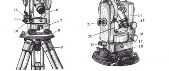
How is a theodolite constructed?
The main components of the theodolite are:
- Frame.
- Spotting scope.
- Guidance system (a system of adjusting and adjusting screws that allows you to accurately set the horizontal and vertical axes of the device and point the telescope at a certain point).
- A plumb bob or optical plummet, used to adjust the vertical and accurately select the position of the device (installation on a point).
- Tripod (tripod, tripod) for installing the device in working position on the ground.
The main element of the device is a telescope, which is used to accurately point at a specific point and determine the parameters of its location relative to the vertical, horizontal or other point with known parameters.
The structure of the theodolite
is based on the guidance system of the main structural element - the sighting tube (or telescope).
It is installed on a special U-shaped stand and can move around a horizontal axis. Changes in telescope inclination are displayed on the vertical circle scale. In turn, the stand together with the pipe can be rotated around a vertical axis. Changes in the position or direction of the telescope are indicated on the horizontal circle scale. All pipe positions can be fixed or adjusted using fine-tuning screws; the accuracy of the result depends on the quality of guidance.
Installation on the ground is done using a tripod. To adjust the horizontal, use a plumb bob and adjusting screws located in the lower part of the body.
All a theodolite is designed for is determining vertical or horizontal angles, allowing you to calculate the distance between points, the difference in the vertical levels of points. The measurement accuracy depends on two parameters:
- Quality of the device.
- Accuracy of calculations.
Attention!
An optical theodolite does not provide definitive data; most values are obtained through subsequent processing and calculations. This is the key feature of the device, distinguishing it from more modern types.
Theodolites are checked and adjusted to identify and eliminate errors caused by deviations from the geometric and optical-mechanical requirements inherent in the design of the device.
1. The movement of the lifting screws should be smooth, measured, without rolling or jamming.
Adjust the screw stroke by rotating the adjusting nut in one direction or another using a pin until a uniform screw stroke is achieved.
Round level
Rice. 3.22. A rod with a round level according to the microscope, equal to the place
| Technical specifications | TZO | T15 | T15K. | | |
| USSR | ||||
| Mean square error of measurement | 30″ | 10″ | 10″ | |
| horizontal angle from one | ||||
| reception | ||||
| With the method of repetitions of three repetitions | 10″ | 5″ | 5″ | |
| Mean square error of measurement | 20″ | 20″ | 20″ | |
| vertical angles | ||||
| Spotting scope | ||||
| Increase | 20* | 25x | 25x | |
| line of sight | 2° | 1°30′ | 1°30′ | |
| Lens focal length, mm | 157 | 200 | 250 | |
| Exit pupil diameter, mm | 1,35 | 1,4 | 1,4 | |
| Rangefinder thread coefficient | 100 | 100 | 100 | |
| Focusing limits, m | From 1 | From 1.2 | From 1.5 | |
| DO oo | DO oo | DO oo | ||
| Unit counting system | ||||
| Working diameter of horizontal circle, mm | 72 | 76 | 90 | |
| » » vertical circle, mm | 72 | 72 | 70 | |
| Circle division price | 10′ | 1° | 1° | |
| Microscope Magnification | 18x | 72x | 65x | |
| Price of the smallest division of the micro scale | 1′ | 1′ | ||
| osprey | ||||
| Reading accuracy | G | 0,1′ | 0,1′ | |
| Level | ||||
| Level division chain for alidade horizon | 45″ | 45″ | 45″ | |
| tall circle | 15″ | |||
| The price of dividing the level with an alidade of verti | 30″ | |||
| cal circle | ||||
| Round level division price | ||||
| Compensator | ||||
| Compensator range | 3,5′ | |||
| Compensation Accuracy | 2″ | |||
| Optical plummet | ||||
| Increase | 2.5x | 2.5x | ||
| line of sight | 4=30′ | 4° 30′ | ||
| Focusing limits, m | From 0.8 | 0,35 | ||
| up to 2 | DO oo | |||
| Weight | ||||
| Theodolite, kg | 2,2 | 3 | 3 | |
| Case, kg | 1,0 | 3,5 | 3,5 | |
| Tripod, kg | 3,8 | 5,3 | 5,3 | |
| Dimensions | ||||
| Theodolite height, mm | 220 | 250 | 250 | |
| Distance from tripod head to axis | 175 | 210 | 210 | |
| telescope distance, mm | ||||
| T5 | T5K | 2T5 | 2T5K | T2 | 2T2 | 020 | 020 A | |
| USSR | GDR | |||||||
| 6″ | 5″ | 5″ | 5″ | 2″ | 2″ | 3″ | 3″ | |
| 3-4″ | 1″ | 1″ | ||||||
| 8—10″ | 8″ | 8—10″ | 8″ | 2,9″ | 3″ | 6—8″ | 6—8″ | |
| 25x | 27x | 27x | 27.5x | 25x | 27.5x | 25x | 25x | |
| 1°30′ | 1°30′ | 1s30′ | 1°30′ | 1°30′ | 1°30′ | G65′ | ||
| 250 | 218,5 | 218,6 | 218,6 | 250 | 250 | 195 | 175 | |
| 1,4 | 1,4 | 1,4 | 1,4 | 1,4 | 1,4 | |||
| 100 | 100 | 100 | 100 | 100 | 100 | 100 | 100 | |
| From 1.5 | From 2 | From 2 | From 2 | From 1.5 | From 2 | From 2.1 | From 1.5 | |
| DO oo | DO oo | DO oo | DO oo | DO oo | to oo | DO oo | to oo | |
| 90 | 95 | 90 | 90 | 90 | 90 | 96 | 86 | |
| 70 | 70 | 70 | 70 | 65 | 65 | 74 | 86 | |
| 1° | 1° | 1° | 1° | 20′ | 20′ | 1° | 1° | |
| 65x | 70s | 71x | 71.1x | 45.6x | 45.6x | |||
| G | 1′ | 1′ | 1′ | 1.» | 1″ | 1′ | 1′ | |
| o, g | 0,1′ | 0,1′ | 0,1′ | 0,1″ | 0,1″ | 0,1″ | 0,1″ | |
| 45″ | 30″ | 30″ | 30″ | 15″ | 15″ | 30″ | 30″ | |
| 15″ | 15″ | 15″ | 15″ | |||||
| 10′ | 8′ | 8′ | ||||||
| 3,5′ | 3,5′ | 4′ | 4′ | |||||
| 2″ | 2″ | 1″ | 1″ | |||||
| 2.5x | 2.5x | 2.5x | 2.5x | 2.5x | 2.5x | 2.1x | 2.1x | |
| 4°30′ | 4С30′ | 4e 30′ | 4930′ | 4°30′ | 4°30′ | |||
| From 0.35 | From 0.3 | From 0.6 | From 0.6 | From 0.3 | From 0.3 | 0,5 | 0,5 | |
| to oo | DO oo | DO oo | DO oo | DO oo | DO oo | DO oo | to oo | |
| 3,5 | 3,5 | 3,7 | 3,5 | 5,2 | 5,2 | 4,3 | 4,0 | |
| 3,5 | 3,0 | 4,7 | 4,7 | 9,5 | 9,5 | 4,4 | 4,4 | |
| 5,3 | 5,3 | 5,3 | 5,3 | 5,3 | 5,3 | 5,6 | 5,6 | |
| 280 | 265 | 335 | 335 | 363 | 335 | 270 | 295 | |
| 230 | 220 | 225 | 225 | 225 | 225 | 240 | 224 | |
2. The azimuthal stability of the tripod and tripod must be ensured when the alidade of the horizontal circle is rotated.
Fix the theodolite on a tripod, bring the vertical axis of rotation of the device to a vertical position, and point the grid of telescope threads at some sharply distinguished object. When applying weak rotational forces to the tripod head, the telescope filament grid should not deviate from the object. Otherwise, tighten the hinge screws (thumbs) of the tripod legs more tightly.
Having achieved the stability of the tripod, they similarly check the stability of the theodolite tripod; if a deviation of the grid from the image of the object is detected, the nuts that regulate the travel of the tripod lifting screws should be tightened.
3. The axis of the cylindrical level when alidating a horizontal circle must be perpendicular to the vertical axis of rotation of the theodolite.
Set the level to be checked parallel to the line connecting the two lifting screws of the tripod and, rotating them in opposite directions, bring the level bubble to the zero point. Then the level is set in the direction of the third lifting screw and the bubble is again brought to the zero point to bring the theodolite's rotation axis to an approximately vertical position. Take a reading along the horizontal circle and rotate the alidade of the horizontal circle exactly 180°, the accuracy of the installation is checked by readings along the horizontal circle. If the level bubble deviates from the zero point, it is moved half of the deflection arc with the corrective (adjustment) level screw, and the other half with the lifting screw of the tripod in the direction in which it stands.
Verification and correction should be carried out until, after rotating the alidade by 180°, the bubble of the cylindrical level either remains at the zero point or deviates from it by no more than 0.5 divisions.
Checking the axis of a cylindrical level against the horizontal alidade can be performed according to the method of G. F. Lysov. To do this, install the theodolite so that the plane of the limb is inclined to the horizon by no more than 2°, then rotate the alidade with the level until the bubble is at the zero point, and take a reading along a horizontal circle, for example 36°18′ . Continue to rotate the alidade until the level bubble reaches the zero point for the second time and make a second reading, for example 218°02.', After this, set the alidade to the average reading ± 90°. In our example, 37°10′.
4. The axis of the circular level should be parallel to the axis of rotation of the theodolite.
Using a corrected cylindrical level on the alidade of the horizontal circle, set the axis of rotation of the theodolite to a vertical position. The round level bubble is then installed at the zero point using three screws securing the round level frame.
5. The sighting axis of the theodolite telescope must be perpendicular to the axis of its rotation.
The axis of rotation of the theodolite is brought to a vertical position and the central point of intersection of the grid of telescope threads is aimed at a distant, clearly visible object. Then they take a reading along a horizontal circle (for example, with a circle to the right P^, move the telescope through the zenith and again point the intersection of the grid threads at the same object, take a reading along a horizontal circle (with a circle to the left L^ and calculate their difference: Px - JIX The resulting difference in readings Ax-P may contain an error caused not only by the influence of non-compliance with the verified condition, i.e., collimation error C, but also by the eccentricity of the alidade, the value of which in individual specimens of theodolites can reach + G. In order to eliminate the influence of the horizontal eccentricity circle in theodolites with one-sided reading, take a reading along a horizontal circle, for example L2. Unfasten the tripod screw, rotate the theodolite in the tripod 180°, bring the vertical axis of rotation of the theodolite to a vertical position. Point again at the same object, take reading P2 and calculate the difference L2 —P2.
To correct, you should set the reading L - S or P + S in a horizontal circle. Then unscrew the cap covering the screws and the mesh screws, and with a pin, with the vertical corrective mesh screws slightly loosened, move the frame with the side correction screws until the intersection of the center of the mesh with the image is aligned observed object. Elimination of collimation error is achieved in several steps.
6. The vertical thread of the mesh (or bisector) must be perpendicular to the axis of rotation of the pipe (lie in the collimation plane of the pipe).
Fix the theodolite on a tripod and carefully bring its vertical axis to a vertical position using a verified cylindrical level on the alidade of a horizontal circle. Select a clearly visible point k (for example, on a wall), rotating the alidade of the horizontal circle with a guiding screw, and see if the image of point k leaves the middle horizontal thread of the grid. If the image of point k deviates from the horizontal thread of the grid by more than three stroke thicknesses for theodolites T5,$2T5, T5K, 2T5K and by a third of a bisector for theodolite ;T 15 (if it moves in the middle between the bisector strokes), then the grid is installed correctly . Otherwise, you should unscrew the cap covering the corrective screws of the reticle, slightly loosen the screws that fasten the eyepiece part to the tube body, and rotate the eyepiece part so that when the alidade of the horizontal circle is rotated, the image of point k does not leave the horizontal thread of the reticle. After installing the thread mesh, close the screws and screw on the cap.
7. The axis of rotation of the telescope must be perpendicular to the vertical axis of rotation of the theodolite.
The main axis of rotation of the theodolite is brought to a vertical position and, having secured the limb, the center of intersection of the grid of threads is directed to point k (for example, on a wall), located 20-30 m from the theodolite at an angle of 30-50° to the horizon, and the alidade is secured. After this, lower the theodolite telescope to approximately its horizontal position and mark on the wall the projection of the central point of intersection of the grid of threads ax. Rotate the alidade by 180°, move the pipe through the zenith and again point the intersection of the central point of the threads at the same point k, then lower the pipe to the same position as in the first case, and mark on the wall the projection of the intersection point of the grid of threads a2. If the points ax and a marked on the wall do not extend beyond the bisector of the threads, then such an inclination of the axis of rotation of the theodolite tube is acceptable. Elimination of non-compliance with the verified condition is carried out only in the workshop.
8. The zero point of the vertical circle should be close to zero.
Place the theodolite in working position. By crossing the central point of the grid of threads of the theodolite telescope, one points at some clearly visible point k, 150-200 m distant, and brings the level bubble on the alidade of the vertical circle to the zero point in theodolites T15, T5 and 2T5. In theodolites T15K, T5 and T5K there is no level with a vertical circle; its role is played by a self-aligning optical compensator system. Take a reading in a vertical circle. The pipe is moved through the zenith and the intersection of the grid of threads is again directed at the central point, the same point k, and before counting along the vertical circle, the level bubble is brought to the zero point when alidating the vertical circle.
The place of zero (MO) is calculated using the formulas:
for theodolites T15, T5 and T5K
(3.2)
where P is the reading in a vertical circle with the circle to the right; J1 - counting in a vertical circle when the circle is to the left;
for theodolites T15K, 2T5 and 2T5K, microscope scales of vertical circles of which have double digitization
(3.3)
If the MO differs from zero by more than double the accuracy of the optical micrometer, it is corrected as follows.
In theodolites T15, T5, 2T5, a level bubble is installed with a vertical circle at the zero point and a reading is made along the vertical circle. Then, using the leveling screw, reduce the reading P-MO or MO-L + 180° by the value of the zero point (add 360° if necessary) and set the index of the reading device to this reading on the vertical circle, and use the adjusting screws for the level of the vertical circle to bring the bubble to zero -point and repeat the verification again. The verification is repeated in this way until the MO is equal to or close to 0°.
In theodolites T5K, 2T5K, bringing MO to 0° or close to it is carried out only in the workshop.
9. One division of a horizontal or vertical circle should be equal to the length of the scale of the reference microscope.
Combine any stroke of a horizontal or vertical circle with the zero stroke of the microscope scale. The countdown is taken from the next stroke of the circle. The difference between the calculated and its nominal value is called re and about m. The value of ren is determined by at least 12 combinations in different sections of each circle.
To correct the horizontal circle microscope theodolite, you must first remove the side cover of the illumination and slightly loosen the screws of the lower block. And then, by moving these screws, and with them the frame with lenses, along the axis, change the magnification of the microscope, i.e., achieve alignment of the strokes of the horizontal circle with the strokes of the microscope scale. The correction begins by moving the upper lens, which will disrupt the sharpness of the image and cause parallax to appear. Then, by moving the lower lens, the sharpness of the image of the strokes is established without parallax noticeable to the eye. Once installation is complete, tighten the screws and check the ren again.
Correction of the vertical circle is carried out similarly to that described for the horizontal circle by moving the objective lenses secured with the screws of the upper block.
10. The theodolite compensator must provide a constant reading in a vertical circle when the vertical axis of the device is tilted within the limits specified in its passport.
To check this condition, select a sighting target and install the theodolite on a tripod so that one of the lifting screws of the tripod is located in the direction of the sighting target. Bring the level bubble at the alidade of the horizontal circle to the zero point and take a reading along the vertical circle at the circle to the right P or the circle to the left L. Then tilt the theodolite with the lifting screw of the tripod in the direction of the sighting target at the angle that limits the range of action of the compensator (determining the amount of tilt by the number of divisions level), check the correct installation of the theodolite using the other two lifting screws, to do this, point the telescope at the same target and take a reading in a vertical circle. The same is done when tilting the theodolite at the same angle in the other direction, i.e. towards the observer.
Readings along a vertical circle obtained when the theodolite is tilted in two opposite directions (with the cylindrical level bubble positioned at the zero point) must be within the accuracy of readings along this circle. In addition, you should make sure that the lateral tilt of the theodolite does not affect the accuracy of measuring vertical angles. To do this, tilt the theodolite at the same angle to the right and left of the observer, point the telescope at the same target and take readings in a vertical circle. The resulting readings must also be within the Circular Reading Accuracy.
11. The sighting axis of the optical plummet, located in the alidate part of the theodolite, must coincide with its vertical axis of rotation.
To perform this verification, the position of the image of a terrain point relative to the center of the grid of threads is observed when the alidade rotates around a vertical axis.
If the image of a terrain point leaves the center of the optical plummet grid, then unscrew two screws and disconnect the optical plummet cover from the side cover of the theodolite.
By slightly loosening the screws that fasten the ocular leg of the optical plummet and moving it in the plane of the side cover, we achieve alignment of the sighting axis of the optical plummet with the vertical axis of rotation of the theodolite.
Again, the position of the terrain point image relative to the center of the grid is observed when the alidade part is rotated. In this case, the image of the terrain point should not move relative to the center of the optical plummet grid.
In theodolites 2T2, 2T5K and 2T5, optical plummets are adjusted only in the workshop.
What is the horizontal circle of theodolite used for?
A horizontal circle is both a certain conventional plane, a geometric concept, and a specific design detail of the device that serves as a support for the telescope stand.
The horizontal circle is used to determine the angles between various objects located around the device
.
When pointing the telescope at certain points, the device is rotated relative to the vertical axis. The angle of rotation is recorded on a scale located on a horizontal circle.
This is the principle of operation of a theodolite - the difference between the initial reading and the value obtained after turning the tube to point at another point is the angular distance between them, which can serve as the basis for many calculations.
Principle of operation
The basic principle of operation of the device is to point the telescope at the target, after which, using the geometric projection of the horizontal and vertical axes observed through the lens, it is possible to measure the deflection angles of each axis through a reading device along the dial.
In order to work with a theodolite, the operator requires a certain level of knowledge in the fields of geometry, mechanics and astronomical geodesy, as well as practical skills in handling high-precision devices. Electronic devices existing in industry greatly simplify operation, but it is also advisable to understand the principles of their operation in advance.
In a simplified form, the procedure for working with a theodolite, regardless of its type, comes down to the following steps:
- Placement of a tripod and alignment of the theodolite on a horizontal surface taken as the reference line;
- Alternately pointing at two conventional marks of an object, first “by eye” using a tube, and then more accurately using aiming screws;
- Fixing the values of the location of points with a vertical or horizontal thread on the sight. In this case, you need to move clockwise;
- Carrying out calculations based on data recorded on a horizontal or vertical limb when focusing on each of the points. Thus, the desired value of the angle between the straight lines on which the desired marks are located will be obtained.
What does the horizontal circle of a theodolite consist of?
The horizontal circle includes two main scales of the device - limb and alidade.
They are designed to measure horizontal angles. One scale remains stationary, while the other rotates along with the sighting tube, showing the amount of deviation from the original position.
Attention!
The operating principle of a vertical circle is practically no different from a horizontal one; it has the same structure and performs similar functions. The only difference is the location in the vertical plane.
Description of the theodolite itself
With its help, fairly accurate measurements of horizontal and vertical angular quantities are made.
Externally, it is made in the form of a U-shaped optical device located on a rotating platform. The device platform is made in the shape of a circle, on which angular divisions are marked. In addition to the horizontal one, there is also a vertical circle with the same angular divisions. To measure range, it is equipped with various rangefinders. Modern theodolites have electronic components that improve the accuracy of measurements.
What are limbus and alidade?
Limb - the main scale of the device, located on a horizontal circle
. It is divided into 360° (sometimes the scale is divided into hail or gon, i.e. into 400 parts). The dial is conditionally motionless - during measurements it is fixed with a screw. If necessary, the dial is detached and installed in a position convenient for measurements - for example, with a zero value at a certain point relative to which measurements will be made.
The alidade in the theodolite
plays the role of a moving scale, showing the angle of deviation from the original value
. The readings are determined using a line applied to the alidade (in some cases, a line sector with a vernier is applied). Any rotation of the telescope will cause the alidade to rotate, which will show the angle of deflection.
Surveying with theodolite using the alignment and perpendicular method
The method of alignments and perpendiculars is well suited for marking work. In this case, we plot right angles on the ground, sequentially moving the tool to the obtained points on the ground. For example, from the base side 1-2 we get control direction 1. The mesh of threads in this case plays the role of laces. Having measured the required distance, we find ourselves at the starting alignment point, and then we work according to the diagram.
You can use a theodolite to break up a rectangular polygon or check the alignment of the broken polygon. The theoretical sum of angles in a closed loop should be 360°. By placing the tool sequentially at each point of the object, we measure the internal angles. For example, a discrepancy of 1° on a 10-meter segment is approximately 20 cm. So, you can evaluate the tolerances depending on the class of the structure, and, if necessary, make adjustments to the alignment of the axes.
Geometric conditions of theodolite
Geometric conditions are the relationships between the locations of all nodes of the device
. The axes of the theodolite must be in strict accordance with each other:
- The vertical and horizontal axes must be perpendicular.
- The axis of rotation of the pipe must be perpendicular to the sighting axis.
- The axis of the cylindrical level (bubble level) must be strictly horizontal.
The vertical axis (alidade rotation axis) and horizontal axis are the main operating parameters of the device; they are subject to periodic verification (monitoring compliance with requirements) or adjustment (adjusting the correct position) before starting work.
Checking the cylindrical level
It requires that it be located in the center of its body during any rotation of the theodolite around its axis. This means that the longitudinal axis of the level must be perpendicular to the vertical axis of the theodolite. This theodolite verification is performed first in order and in the following sequence:
- with two lifting screws located along the axis of the level, its bubble is brought out in the center of the ampoule;
- with the third screw, after rotating the theodolite body 90 degrees, the level is set to the center;
- turning the theodolite 180 degrees, the expectation of setting the level in the central position may not be justified;
- when the bubble deviates two divisions to one side, adjustment should begin;
- half the displacement of the bubble is adjusted with a screwdriver (pin) and a correction screw;
- the remaining part of the deviation is removed by the third lifting screw;
- verification will be considered if the level is in the center at any point where the theodolite stops within the prescribed 360 degrees.
How to check a theodolite?
For correct, accurate operation of the device, high-quality adjustment of its position and correspondence of the axes is required. To achieve this, regular checks and adjustments are carried out.
, allowing you to accurately install the device and ensure the correct position of the axes and planes.
The check is carried out in stages:
- Installation on a point. The position of the tripod is adjusted so that the plumb line accurately points to a point with known parameters (standing point) marked on the ground.
- Setting the horizontal plane. The horizontal is adjusted using the bubble level, then the device is turned 180° and adjusted again. An acceptable position is considered to be a discrepancy between the position of the bubble and no more than 1 division.
- Installation of the sighting axis. A distant point is selected and measured. Then the pipe is rotated 180°, the device is turned around and measurements are taken again (in other words, the parameters of the point are measured in the CP or CL positions). Then the limb is unfastened and rotated 180°, after which all operations are repeated. The obtained values are calculated using a special method; the result must correspond to the passport values. If discrepancies are detected, the perpendicularity of the sighting axis or the axis of rotation of the pipe is adjusted.
All checks or adjustments are made before using the theodolite. To adjust the optics, the device is sent to a specialized workshop or factory.
Round level
It is checked in the traditional way, as in almost other instruments (levels, total stations, and so on). As a rule, the round level ampoule itself is positioned between two lifting screws. And with the help of all three screws, the round vial is brought to the center of the level ampoule. By rotating the theodolite 180 degrees, we observe whether there is a deviation of the round air bubble from the center or not. If there is such a displacement beyond the designated circle line on the ampoule, the level is adjusted. To do this, corrective screws are used to adjust half the displacement value. The remaining deviation is brought to the center of the ampoule by lifting screws. To confirm the level adjustment, the verification is repeated again. The constant presence of the level in the center means the fulfillment of the verified condition.
Standard range of theodolites in accordance with GOST
Theodolite is a critical measuring instrument, the accuracy and quality of which determines the result of construction, laying roads or tunnels, etc. Therefore, all technical parameters of theodolites are clearly defined and regulated by GOST 10529-96.
In particular, the devices are divided into groups:
- Highly accurate.
- Accurate.
- Technical.
Letters in the designation of devices indicate:
- T - theodolite.
- M - surveyor's.
- K - equipped with a plane position compensator.
- P - direct vision (the image is not inverted).
- A - autocollimation.
- E - electronic.
The numbers in the designation indicate the average error. In new samples, the very first digit is the modification number. Each group has its own list of models, the technical characteristics of which meet certain requirements.
Error of closed theodolite traverse, discrepancy
As a result of simple calculations, we obtain a discrepancy, which we compare with the acceptable one. If the value is within tolerance, the error spreads proportionally to the sides of the polygon.
For a closed theodolite traverse, the error is determined by the formula:
Where
the sum of angles is actual (measured), and the sum of angles is theoretical, that is, which should be according to the laws of geometry.
The theoretical sum of angles is calculated using the formula:
Where n is the number of measured angles.
The permissible error of the sum of the angles of a closed theodolite traverse is determined by the formula:
If the actual error is greater than the permissible one, we check the records again; if this is not the problem, we take the readings again. If the error is less than or equal to the permissible one, we calculate the correction using the formula:
The value is spread across all angles. If the number is not an integer, we introduce corrections to some angles more than to others.
What are non-repetitive theodolites?
Non-repeating theodolites have a rigidly fixed dial that turns only when the locking screw is loosened to adjust or set the point to zero.
This system is older, but is still used quite widely.
A rigidly fixed dial reduces the possibility of errors, but deprives the design of some of the capabilities inherent in repeatable samples.
Phototheodolite
A specific type of theodolite designed for precise shooting of objects with reference to a coordinate system, angular reference or other parameters
. It can be designed as a camera, the lens of which simultaneously performs the function of a theodolite telescope, or a separate camera and a telescope.
The most common phototheodolite model is the Photeo 19/1318 kit, which allows you to produce high-quality images for precise terrain measurements for research or applied purposes.
Gyrotheodolite
The gyrotheodolite is designed to work in mine or field conditions without reference to a triangulation system
.
Structurally, it is a combination of a high-precision gyrocompass with an optical theodolite. The device has the ability to accurately determine the true azimuth (the error is no more than 6-60″), and work in any weather or climatic conditions.
From a practical point of view, this is a completely ordinary theodolite; how to use it or how to configure it is not much different from optical models. A gyrocompass, in fact, is an additional device that makes it possible to link axes to a coordinate system.
The most common models of gyrotheodolites are 01-B1, MVT-2, MT-1 and others.
Electronic
The electronic theodolite (modern name - tacheometer) is the most advanced design currently used . The device has a built-in processor that performs the necessary calculations based on the received readings, which almost completely eliminates the possibility of errors.
In addition, all data on the surveyed points remains in the device’s memory, greatly simplifying the work and eliminating the need to re-install and point the device. The ability to use in the dark and in any weather conditions makes the electronic theodolite the most accurate and high-quality device.
The most common models of electronic theodolites include RGK T-05, RGK T-20, VEGA TEO-5B and others.
Types of devices
The following types of devices are available:
- Mechanical . It is the simplest in design and the cheapest type, but it also has the lowest accuracy, so it is not suitable for serious work.
- Electronic . An electronic theodolite is convenient because it is equipped with a device for reading and processing the results; the surveyor just needs to set it correctly, and the device will do the rest itself.
- Optical . The most widely used is the optical theodolite. It does not perform calculations like an electronic one, but the cost of the device and the quality of measurements are attractive.
- Laser . These theodolites are the most expensive, but also more advanced devices. They allow you to take measurements with great accuracy and are convenient to use, but it makes sense to purchase them only for regular work, where the requirements for the result are high.
Two fundamentally different types of theodolites differ in the mobility of the alidade and limb. In repeating types, these elements can be fixed one by one, and readings can be taken using the method of sequential repetitions. Ordinary options do not allow this, since the alidade with the axis represents a single fixed whole, and each measurement requires a separate setting.
How to prepare a theodolite for work?
Theodolite is a device capable of adjusting almost all mechanical parameters immediately before use. The need to ensure high measurement accuracy requires constant checking of the performance and quality of the readings, which should not go beyond acceptable limits.
Preparing the theodolite for work is carried out in stages:
- Installing the tripod on the point.
- Installation of theodolite on a tripod, fixation with a screw.
- Vertical and horizontal adjustment (centering and leveling).
- Setting up (focusing) the telescope and microscope.
- Installation and connection of lighting.
All these actions may require more or less time depending on the state of the device and previous settings.
Attention !
The device passport contains clear and detailed instructions on how all preparatory operations are carried out. Before starting work, you should carefully read the instructions and comply with all its requirements during practical operations.
Instructions for bringing the theodolite into working position
Preparing a theodolite for work includes three main stages: centering, leveling and focusing.
Centering
It involves installing the device with a tripod above the central area of the measuring point. During geodetic operations, a plumb line or an optical plummet is used for centering. The accuracy of the work performed and the accuracy of the center are interrelated. The central point of the geodetic point is determined by eye. The device is placed above this central sector.
The lower area of the deadbolt is equipped with a hook on which to hang a plumb line. Observing the tip of the plumb weight and moving the legs of the tripod, fix the device with an accuracy of 3–5 cm. So that the distance between the tip of the weight and the center does not exceed 3–5 cm. Next, you should press the tripod into the ground, monitoring the position of the device relative to the weight using the weight. center.
The last step should be to loosen the tripod screw. When moving the tribrach with the fingers of your right hand, the tip of the plumb weight should be directly above the center. Having done this, you can tighten the head screw.
Leveling
The ultimate goal of this stage is to ensure that the horizontal circle of the theodolite is in the horizontal plane. The axis of rotation must take a vertical position. The theodolite must be rotated so that the cylindrical level of the rotary ruler is located along the two lifting screws.
By loosening or tightening the lifting screws, the level bubble is brought to the zero point. The bubble can be either on the left side of the middle or on the right. This determines in which direction the lifting screws need to be rotated.
Then the theodolite is turned 90 degrees. Connect the third lifting screw. The bubble leads to the zero point.
Leveling control is carried out by turning the device into several different positions. Leveling is considered successful if, in any arbitrary position, the level bubble deviates from the middle by no more than one notch.
The scheme under consideration is applicable if the alidade of the horizontal circle is equipped with a cylindrical level. Some theodolites have a round level with a rotating ruler. In this situation, the device is fixed in an arbitrary position. They begin to alternately rotate the three lifting screws, bringing the membrane capsule to the zero mark. Carry out quality control of the leveling performed.
Having sequentially centered and leveled the theodolite, you can find that the axis of rotation of the device has assumed a vertical position and passes through the center of the geodetic point.
Focusing
The grid of threads of this geodetic device is focused just before the start of measuring work. Rotate the diopter ring of the eyepiece of the observation tube of the device until a clear picture of the reticle appears.
Focus the scale of the reading mechanism by rotating the diopter ring of the microscope until a clear gradation of the scale is observed. When carrying out focusing and subsequent measurements, try to achieve sufficient illumination of the scale using a backlight mirror.
This is interesting: Types and criteria for choosing spatulas for puttying walls - let’s take a closer look
How to measure angles?
Measuring angles is the main function of the device. In fact, this is the only operation that a theodolite can perform.
The first thing to consider is measuring horizontal angles with a theodolite. The device installed on the standing point (the vertex of the angle being measured) and prepared for work (adjusted) is aimed at the point that determines the side of the angle.
To do this, the tube is aimed by hand so that the point is in the field of view of the viewfinder, after which fine adjustment is made using the alidade adjustment screws. In this case, the dial can be left in its original position or set to the zero position, which will simplify the calculations. The readings are recorded in the measurement log.
Then the pipe is sighted at the second point in a similar way. The position of the alidade will indicate the size of the angle between the first and second points relative to the vertex - the point at which the device is standing.
Vertical angles are measured in a similar way, but readings are taken from the vertical circle of the theodolite. There are two positions of the vertical circle - KP and KL, meaning the right and left positions of the vertical circle relative to the pipe, respectively. When making calculations, this should be taken into account, since with multiple measurements an error may occur that can radically affect the result.
Theodolite measurement
Measurements of horizontal and vertical angles are carried out using a proven device. Before taking measurements, it is necessary to check the smooth movement of all moving parts of the device. Rotate the device's alidade, screws, and cremarriers. Reducing possible errors is achieved by rotating the alidade in the selected direction. Movements should be smooth without sudden jerks. It is not advisable to carry out reciprocating movements.
Before starting to measure the angle in the horizontal plane, the device is installed vertically above the reference point. Then the necessary preparatory actions are carried out. To get good results, you should repeat these steps several times. This will eliminate possible errors and inaccuracies that could negatively affect the measurement result.
The processes for measuring angles in different planes are fundamentally different. These differences are:
- The horizontal angle is calculated as the arithmetic difference between the measured values. The vertical angle is determined between the plane and the amount of elevation of the telescope.
- The horizontal angle is measured on pre-selected areas of the circle, the vertical angle is measured without any rearrangements.
- The number of methods for determining horizontal angles exceeds this number for vertical angles.
Processing of the measurements taken consists of calculating average values. The result is subtracted from other results. In this way the “reduced direction” is obtained. An assessment of the collimation error is used to confirm the accuracy of the measurements taken. It is obtained on the basis of available passport data on the accuracy of the theodolite.
If you need to obtain more accurate calculations, you can use the methods of probability theory and mathematical statistics. Calculate the mathematical expectation and variance.