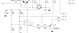
Features of measuring resistor resistance with a multimeter
In order to find out the resistance of the resistor, you need to use a conventional multimeter. The measurement principle is based on Ohm's law, which states that current is directly proportional to voltage and inversely proportional to resistance. Resistance is determined indirectly using the formula R = U/I. That is, with known voltage and current it is easy to determine the resistance.
If dial testers were previously used, today radio amateurs most often use digital multimeters with a rotary switch to check the serviceability of resistors, with the help of which the type of operating mode and measurement range are set.
Digital resistor tester
To measure the value of R, the switch is set to the Ω range. This device comes with one set of probes of different colors. It is customary to insert the red probe into the com hole, and the black probe into VΩCX+.
What is a multimeter
A multimeter is a device that can measure AC or DC current, voltage and resistance. It replaces three analog or digital instruments at once: ammeter, voltmeter and ohmmeter. It is also capable of changing the main indicators of any electrical network and ringing it. There are two types of multimeters: digital and analog. The first are portable devices with a display to display the results. Most multimeters on the market today are digital. The second type is already outdated and is no longer popular. It looks like a regular measuring instrument with a graduation scale and an analog needle showing the measurement value.
You might be interested in Measuring current with a multimeter
Modern digital multimeter
How to check a resistor without desoldering: visual check
The process of checking a resistor for functionality directly on the board without completely desoldering is a rather labor-intensive task, so you can first determine the burnt part visually. First of all, inspect the case for damage and chips, and the reliability of fastening the terminals.
Malfunctions are indicated by:
- Darkening of the body. A burnt resistor has a darkened surface - completely or partially in the form of rings. Slight darkening does not indicate a malfunction, but only overheating, which did not lead to complete failure of the part.
- The appearance of a characteristic odor.
- Erasing markings.
- Presence of burnt tracks on the board
If conditions allow, the faulty resistor is soldered off, and a new one with the same rating is soldered in its place.
Attention!
Inspection does not guarantee an accurate determination of serviceability; the resistor may look like new even with a broken contact.
Visual inspection
Violation of the normal operating mode causes overheating of the part, therefore, in most cases, the problematic element can be identified by its appearance. This can be either a change in the color of the case or its complete or partial destruction. In such cases, it is necessary to replace the burnt element.
Figure 4. A clear example of how a resistor can burn out
Pay attention to the photo above, the component clearly needs to be replaced, while the neighboring parts “2” and “3” may be working, but they need to be checked.
Preparing a multimeter for measurements: what settings to set
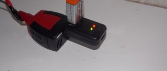
Before measurements, the device is prepared for operation. To do this, it is turned on and the ends of the probes are short-circuited with each other. If zeros appear on the display, then the device is working properly and there is no break in the circuit. The display may show fractions of an Ohm rather than zeros.
Preparing the device for testing
When the probes are open, a working multimeter displays the number 1 and the measurement range. The cable cords are connected in accordance with the mode that you need - “Dialing” or “Measurement”.
How to ring a resistor
The “Continuity” mode (not available in all testers) is used to make sure that there is no short circuit in the circuits running through or parallel to the resistor. To install it, turn the knob towards the diode icon. If there is a current-carrying circuit between the probe installation points, then a sound signal is generated through the speaker.
Dialing mode
This mode is used only for resistors whose value does not exceed 70 Ohms. It makes no sense to use it for parts with a high rating, since the signal is so weak that it may not be heard.
Troubleshooting algorithm
Visual inspection
How to test a generator diode bridge using a multimeter
Any repair begins with an external inspection of the board
It is necessary to examine all components without instruments and pay special attention to yellowed, blackened parts and components with traces of soot or soot. For external inspection, a magnifying glass or microscope can help you if you are working with dense mounting of SMD components. Torn parts may indicate not only a local problem, but also a problem in the strapping elements of this part
For example, an exploding transistor could drag along a couple of elements in the harness
Torn parts may indicate not only a local problem, but also a problem in the strapping elements of that part. For example, an exploding transistor could drag down a couple of elements in the harness.
An area on a board that turns yellow due to temperature does not always indicate the consequences of part burnout. Sometimes this happens as a result of long-term operation of the device; when checked, all parts may turn out to be intact.
In addition to inspecting external defects and traces of burning, it is worth sniffing to check if there is an unpleasant odor like burnt rubber. If you find a blackened element, you need to check it. It may have one of three malfunctions:
- Break.
- Short circuit.
- Not up to par.
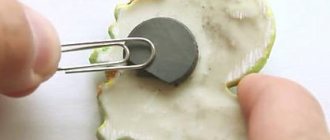
Sometimes a breakdown is so obvious that it can be determined without a multimeter, as in the example in the photo:
Checking the resistor for open circuit
You can check the serviceability using a regular dial tone or a tester in diode testing mode with sound indication (see photo below). It is worth noting that by testing you can only check resistors with a resistance of units of Ohms - tens of kOhms. And not every continuity can handle 100 kOhm.
To check, you just need to connect both probes to the terminals of the resistor, it doesn’t matter whether it’s an SMD component or an output one. A quick check can be carried out without desoldering, after which you can still desolder the suspicious elements and check again for a break
Attention! When checking parts without desoldering them from the printed circuit board, be careful - you may be misled by parallel elements. This is true both when checking without instruments and when checking with a multimeter. Don’t be lazy and better unsolder the suspicious part
This way you can only check those resistors where you are sure that nothing is installed parallel to them in the circuit
Don't be lazy and better unsolder the suspicious part. This way you can only check those resistors where you are sure that nothing is installed parallel to them in the circuit.
Short circuit check
In addition to the break, the resistor could have short-circuited. If you use a dial, it should be low-impedance, for example, on an incandescent lamp. Because high-resistance LED dials “ring” the circuit with a resistance of tens of kOhms without significant changes in the brightness of the glow. Sound indicators cope with this test better than LEDs. By the frequency of beeping one can judge the integrity of the circuit; complex measuring instruments such as a multimeter and ohmmeter are in first place in terms of reliability.
Checking for short circuit is carried out in one way, let's look at the instructions step by step:
- Measure a section of the circuit with an ohmmeter, continuity tester or other device.
- If its resistance tends to zero and continuity indicates a short circuit, unsolder the suspicious element.
- Check the section of the circuit already without the element; if the short circuit is gone, you have found a fault; if not, solder the neighboring ones until it goes away.
- The remaining elements are mounted back, the one after which the short circuit is gone is replaced.
- Check the work results for the presence of short circuits.
Here is a clear example that a burnt resistor has left marks on neighboring resistors; there is a possibility that they are also damaged:
The resistor has turned black from the high temperature, not only traces of burning are visible on the neighboring elements, but also traces of overheated paint, its color has changed, and part of the conductive resistive layer could be damaged.
The video below clearly shows how to check a resistor with a multimeter:
How to determine the resistor value by marking
To determine performance, it is advisable to know the nominal value. We described in detail how to determine the resistor value by color marking in this article.
Let's add a little information about the methods of marking SMD resistors. Due to their small size, it is almost impossible to apply traditional color markings on them, so a special identification system is provided. The designation includes: 3 or 4 digits, 2 digits and a letter.
In the first system, the first two or three digits characterize the numerical value of the resistor, and the last is the multiplier indicator, indicating the power to which 10 is raised to obtain the final result. If the resistance is below 1 ohm, then the symbol R is used to locate the decimal point. For example, a resistance of 0.05 ohms looks like 0R05.
High-precision resistors are very small in size and therefore require compact markings. It consists of three digits - the first two are the code, and the third is the multiplier. Each code corresponds to a three-digit resistance value determined from the table. This marking is carried out in accordance with the EIA-96 standard, developed for resistors with a resistance tolerance of no more than 1%.
Code table for precision resistors
| Code | Meaning | Code | Meaning | Code | Meaning | Code | Meaning | Code | Meaning | ||
| 01 | 100 | 17 | 147 | 33 | 215 | 49 | 316 | 65 | 464 | 81 | 681 |
| 02 | 102 | 18 | 150 | 34 | 221 | 50 | 324 | 66 | 475 | 82 | 698 |
| 03 | 105 | 19 | 154 | 35 | 226 | 51 | 332 | 67 | 487 | 83 | 715 |
| 04 | 107 | 20 | 158 | 36 | 232 | 52 | 340 | 68 | 499 | 84 | 732 |
| 05 | 110 | 21 | 162 | 37 | 237 | 53 | 348 | 69 | 511 | 85 | 750 |
| 06 | 113 | 22 | 165 | 38 | 243 | 54 | 357 | 70 | 523 | 86 | 768 |
| 07 | 115 | 23 | 169 | 39 | 249 | 55 | 365 | 71 | 536 | 87 | 787 |
| 08 | 118 | 24 | 174 | 40 | 255 | 56 | 374 | 72 | 549 | 88 | 806 |
| 09 | 121 | 25 | 178 | 41 | 261 | 57 | 383 | 73 | 562 | 89 | 825 |
| 10 | 124 | 26 | 182 | 42 | 267 | 58 | 392 | 74 | 576 | 90 | 845 |
| 11 | 127 | 27 | 187 | 43 | 274 | 59 | 402 | 75 | 590 | 91 | 866 |
| 12 | 130 | 28 | 191 | 44 | 280 | 60 | 412 | 76 | 604 | 92 | 887 |
| 13 | 133 | 29 | 196 | 45 | 287 | 61 | 422 | 77 | 619 | 93 | 909 |
| 14 | 137 | 30 | 200 | 46 | 294 | 62 | 432 | 78 | 634 | 94 | 931 |
| 15 | 140 | 31 | 205 | 47 | 301 | 63 | 443 | 79 | 649 | 95 | 953 |
| 16 | 143 | 32 | 210 | 48 | 309 | 64 | 453 | 80 | 665 | 96 | 976 |
Validation check
If the part is soldered, then this stage will guarantee its functionality. For testing we need to know the denomination. How to identify it by markings was written above.
The algorithm of our actions is as follows:
- We connect the probes as in the previous testing.
- We turn on the resistance measurement (the range is shown in Figure 6) in a mode greater than the nominal value, but as close as possible to it. For example, we need to test a 47 kOhm resistor, therefore, we need to select the “200K” range.
Figure 6. Resistance measurement ranges (marked in red) - We touch the terminals with the probes, take readings and compare them with the nominal value. If they do not match, and this can be guaranteed with a probability close to 100%, do not despair. Both the error of the device and the tolerance of the element itself should be taken into account. A little clarification is necessary here.
Checking the resistance of a fixed resistor
After preparing the device for use, measurements begin. To do this, unsolder one of the resistance legs. One of the probes is connected to the sealed leg, the second to the free one. If the resistor is working properly, the display will show a reading corresponding to the nominal value within the tolerance.
How to check the resistance of a resistor
When the circuit is broken, “1” lights up on the screen.
Attention!
Before measurement, the regulator sets the switch to the highest value closest to the nominal value. If the regulator has been adjusted to a value less than the nominal value of the part, then the measurement results will not be displayed on the display, since the internal locking of the tester is triggered.
If a capacitor is soldered to one side of the resistor in the circuit, then the leg on this side can conditionally be considered free-hanging. And in this case, you can carry out measurements without soldering the resistor.
SMD resistors are surface-mount components whose resistance measurement is complicated by their small size. They are usually checked, like all fixed resistors, by unsoldering one leg.
Checking the variable resistor
Checking variable resistors that have at least three legs without removing them from the circuit is more difficult than checking a fixed resistor.
Variable resistor
The easiest option is to position the resistor at the very beginning of the circuit, since one of the outer “legs” is connected through a capacitor. Therefore, in terms of direct current, it is equivalent to free-hanging. This measurement method allows you to determine the total resistance that is present between the extreme contacts.
It is possible to carry out accurate measurements of the resistance of the resistor by desoldering it from the circuit. The new part is checked in the same way as the soldered part. Measurement steps:
- The multimeter is switched on to measurement mode.
- The tentacles are connected to the outer legs. This allows you to determine the total resistance. The value on the display should not differ from the nominal value by more than the required tolerance. The tolerance value is characterized by the last ring in the color coding. It is expressed as a percentage of the nominal value.
- If the total resistance corresponds to the nominal resistance, then measure the resistance between the middle and outer legs. After connecting the “crocodiles,” rotate the variable resistor knob in one of the directions. The resistance either smoothly increases to the previously set total value, or decreases to zero. In case of the most common malfunction (loss of current collector contact), the device shows infinity.