The article is posted in the category|subcategory
- Water supply
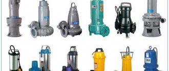
- Pump equipment
Author
Vladimir Ermolov
—
Sep 30, 2015 Updated: March 21, 2019
- 1 Purpose of the pressure switch and principle of operation
- 2 Selecting an installation location
- 3 Connection of pressure switch
- 4 Rules for selecting equipment
- 5 Settings
The efficiency of autonomous water supply in a private house or on a summer cottage is largely ensured by the water pressure switch for the pump, however, for its correct operation, it is necessary to correctly install and operate the equipment. Once you understand the operating principle of this device, you will be able to appreciate its necessity and the importance of trouble-free operation.
Purpose of the pressure switch and operating principle
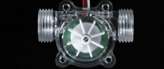
Pumping stations are usually equipped with automation to monitor and control the operation, since turning on and off pumping equipment in autonomous mode is extremely necessary. Performing these operations manually will require constant attention to the system and will not allow the inhabitants of the house to go about their business, work and relax.
A sufficient level of control is provided by the pressure switch. It is a block with a plastic casing. Inside the housing there are two springs, each of which is “responsible” for setting the value of the extreme position (parameters for turning the pump on and off) .
Diagram of a water pressure switch for a pump
The relay is functionally connected to a hydraulic accumulator, which contains water and compressed air; the media come into contact through a flexible elastic membrane. In the working position, the water in the tank presses on the air through the dividing partition, creating a certain pressure. As water is consumed, its volume decreases and the pressure decreases. When a certain value (set on the relay) is reached, the pump turns on and water is pumped into the tank until the value set on the second spring is reached.
The connection diagram for a water pressure switch for a pump provides for connecting the equipment to a water supply system, a pump and an electrical power supply network.
Purpose and device
In order to maintain constant pressure in the water supply system of a private house, two devices are needed - a hydraulic accumulator and a pressure switch. Both of these devices are connected to the pump through a pipeline - the pressure switch is located in the middle between the pump and the accumulator. Most often it is located in close proximity to this tank, but some models can be installed on the pump body (even submersible). Let's understand the purpose of these devices and how the system works.
One of the pump connection diagrams
A hydraulic accumulator is a container divided into two halves by an elastic bulb or membrane. In one there is air under some pressure, in the second water is pumped. The water pressure in the accumulator and the amount of water that can be pumped into it are regulated by the amount of pumped air. The more air there is, the higher the pressure is maintained in the system. But at the same time, less water can be pumped into the container. Usually it is possible to pump no more than half the volume into the container. That is, no more than 40-50 liters can be pumped into a hydraulic accumulator with a volume of 100 liters.
For normal operation of household appliances, a range of 1.4 atm - 2.8 atm is required. To maintain such a framework, a pressure switch is required. It has two response limits - upper and lower. When the lower limit is reached, the relay starts the pump, it pumps water into the accumulator, and the pressure in it (and in the system) increases. When the system pressure reaches the upper limit, the relay turns off the pump.
In a scheme with a hydraulic accumulator, water is consumed from the tank for some time. When enough has flowed out for the pressure to drop to the lower response threshold, the pump will turn on. This is how this system works.
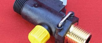
Pressure switch device
This device consists of two parts - electric and hydraulic. The electrical part is a group of contacts that closes and opens turning the pump on/off. The hydraulic part is a membrane that exerts pressure on the metal base and springs (large and small) with the help of which the pump on/off pressure can be changed.
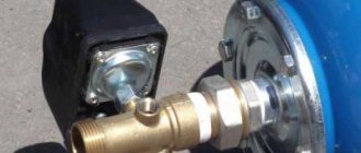
Water pressure switch device
The hydraulic outlet is located on the back of the relay. This can be an outlet with an external thread or with an American-type nut. The second option is more convenient during installation - in the first case, you either need to look for an adapter with a union nut of a suitable size or twist the device itself, screwing it onto the thread, but this is not always possible.
Related article: Do-it-yourself vegetable storage
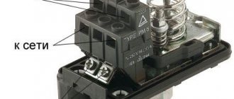
The electrical inputs are also located on the back of the case, and the terminal block itself, where the wires are connected, is hidden under the cover.
Types and varieties
There are two types of water pressure switches: mechanical and electronic. Mechanical ones are much cheaper and are usually preferred, while electronic ones are mainly delivered to order.
| Name | Pressure adjustment limit | Factory settings | Manufacturer/country | Device protection class | Price |
| RDM-5 Gilex | 1- 4.6 atm | 1.4 - 2.8 atm | Gilex/Russia | IP 44 | 13-15$ |
| Italtecnica РМ/5G (m) 1/4″ | 1 - 5 atm | 1.4 - 2.8 atm | Italy | IP 44 | 27-30$ |
| Italtecnica RT/12 (m) | 1 - 12 atm | 5 - 7 atm | Italy | IP 44 | 27-30$ |
| Grundfos (Condor) MDR 5-5 | 1.5 - 5 atm | 2.8 - 4.1 atm | Germany | IP 54 | 55-75$ |
| Italtecnica PM53W 1″ | 1.5 - 5 atm | Italy | 7-11 $ | ||
| Genebre 3781 1/4″ | 1 - 4 atm | 0.4 - 2.8 atm | Spain | 7-13$ |
The difference in prices in different stores can be more than significant. Although, as usual, when buying cheap copies, there is a risk of running into a fake.
Choosing an installation location
For correct operation of the equipment, the pressure switch must be connected to the pump in such a way as to avoid the influence of turbulence and sudden pressure changes when the pumping equipment is turned on and during its operation. The best place for this is in the immediate vicinity of the hydraulic accumulator.
Before installing the pressure switch, pay attention to the operating mode recommended by the manufacturer, in particular, the permissible temperature and humidity values. Some models can only work in heated rooms.
In the classic scheme for connecting a pressure switch to a deep-water pump for an autonomous water supply, the following equipment is installed in front of the relay:
- pumping unit,
- check valve,
- pipeline,
- flow shut-off valve,
- drainage to the sewer,
- filter for preliminary (coarse) cleaning.
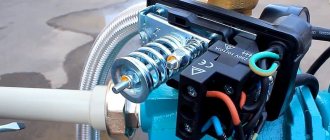
When using many modern models of surface-type pumping units, installing a water pressure switch for a pump can be much simpler: block installation is carried out when the relay is installed together with the pump. The pumping unit has a special fitting, so the user does not need to independently search for the most suitable installation location. The check valve and filters for water purification in such models are often built-in.
Connecting the pressure switch to a submersible pump can also be done by placing the hydraulic accumulator in the caisson and even in the well itself, since waterproof design of the control equipment is often required and the operating conditions of the pressure switch may allow its location in such places.
The connection diagram for a pressure switch and a pumping station with a surface pump differs slightly from the diagram with a submersible unit in the sequence of arrangement of some elements
Obviously, the choice of installation method and location depends on the design of the equipment; usually all recommendations in this regard are indicated by the manufacturer in the accompanying documentation.
Connecting a pressure switch
There are two commonly used schemes for connecting the pump automation and pressure switch. The method recommended by the manufacturer is always indicated in the accompanying documentation, but it will be useful to familiarize yourself with the possible schemes.
Important: When working, you must follow the sequence: first, the relay is connected to the water supply, and then to the electrical network.
1 way
The relay is mounted on the pipeline (the choice of location is made taking into account the above rules and recommendations). Installation is carried out using a tee connected to a transition fitting (it can be replaced by a drain hose).
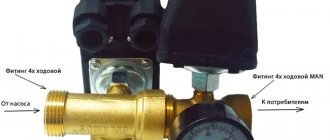
Method 2
The hydraulic accumulator is equipped with a fitting having five outputs , to which they connect:
- pipeline from the source of water intake,
- relay,
- pressure gauge,
- pipeline supplying water to the house,
- the hydraulic accumulator itself.
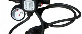
The relay, in turn, is connected to a submersible or external pump and a 220 V power supply.
Connection diagram of the water pressure switch to the submersible pump
The following recommendations apply to both options:
- The need to seal threaded connections using hemp and sealant or using FUM tape,
- In order to make the connection, you will need to rotate the device on the fitting, but an alternative would be to use an “American” connection.
- The electrical connection must be made using a cable, the cross-section of which is selected in accordance with the power of the pumping unit (usually equipment no more than 2 kW is used, for which a conductor with a cross-section of 2.5 sq. mm is sufficient).
- Connection terminals are usually marked for easier installation, however, if such markings are missing, this will not be a big problem - the purpose of each terminal is not difficult to determine from the diagram.
- The presence of a grounding terminal makes grounding of the equipment mandatory.
All the nuances are determined by the connection diagram for a submersible pump with a pressure switch or a similar connection for an external pumping unit supplied with the equipment.
Adjusting the water pressure switch
Let's consider the process of adjusting the most popular model - RDM-5. It is produced by different factories. The adjustment limits change, since different sized water pipes require different pressures. This device leaves the factory with a basic setting. Usually this is 1.4-1.5 atm - the lower threshold and 2.8-2.9 atm - the upper threshold. If you are not satisfied with some parameter, you can reconfigure it as required. This procedure is usually necessary when installing a Jacuzzi: the standard pressure of 2.5-2.9 atm is not enough for the required effect. In most other cases, reconfiguration is not required.
The passport contains a full description
The water pressure switch RDM-5 has two springs, which regulate the threshold for turning off/on the pump. These springs differ in size and purpose:
- the large one regulates the limits (both upper and lower);
- a small one changes the delta - the gap between the upper and lower boundaries.
The parameters change when tightening or unscrewing the nuts on the springs. If you tighten the nuts, the pressure increases, if you loosen it, it decreases. There is no need to tightly tighten the nuts; one revolution is a change of about 0.6-0.8 atm, and this is usually a lot.
How to determine relay response thresholds
The pump activation threshold (and the lower pressure threshold on the water pressure switch) are related to the pressure in the air part of the accumulator - the minimum pressure in the system should be 0.1-0.2 atm higher. For example, if the pressure in the container is 1.4 atm, the shutdown threshold is desirable to be 1.6 atm. With these parameters, the tank membrane will last longer. But in order for the pump to work under normal conditions, look at its characteristics. It also has a lower pressure threshold. So, it should not be higher than the selected value (lower or equal). Based on these three parameters, you select the switching threshold.
By the way, the pressure in the accumulator must be checked before setting - there are significant deviations from the declared parameters. A nipple is hidden under the removable cover (it looks and is located in different places in different models). Through it you can connect a pressure gauge (can be a car one or the one you have) and see the actual pressure. By the way, it can be adjusted through the same nipple - increased or decreased if necessary.
Shutdown thresholds depend on system components
The upper threshold—pump shutdown—is set automatically during adjustment. The relay in the initial state is set to some pressure difference (delta). This difference is usually 1.4-1.6 atm. So if you set the switch-on, for example, to 1.6 atm, the switch-off threshold will automatically be set at 3.0-3.2 atm (depending on the relay settings). If you need higher pressure (to raise water to the second floor, for example, or the system has many water points), you can increase the shutdown threshold. But there are limitations:
- Parameters of the relay itself. The upper limit is fixed and in household models usually does not exceed 4 atm. It’s simply not possible to put up more.
- Upper limit of pump pressure. This parameter is also fixed and the pump must be turned off no less than 0.2-0.4 atm before the declared characteristics. For example, the upper pressure threshold of the pump is 3.8 atm, the shutdown threshold on the water pressure switch should be no higher than 3.6 atm. But in order for the pump to work for a long time and without overloads, it is better to make a larger difference - overloads have too bad an effect on the operating life.
Related article: Curtains for the living room - 150 photos of fashionable new items for 2019
That's all for choosing the water pressure switch settings. In practice, when setting up the system, you have to adjust the selected parameters in one direction or another, because you need to select everything so that all water points, including household appliances, work normally. Therefore, it is often said that parameters are chosen using the “scientific poker” method.
Equipment selection rules
- For autonomous water supply systems, you should choose a relay for household use. Such systems are characterized by basic parameters: the maximum pressure value is no more than 5 atmospheres, operating pressure values are usually in the range from 1.4 to 2.8 atm.
- When setting up the relay, it is important to remember that the magnitude of the difference between the limit values (settings on the springs) directly affects the volume of water that the pump, with such settings, will pump into the accumulator reservoir. A large volume means that the pumping unit will turn on less often, but the technical capabilities of the system must not be exceeded in this regard.
- You should not save excessively by purchasing a relay of unknown origin. Such equipment will not only fail to ensure correct operation, but will also most likely cause damage to other equipment included in the system.
- Connecting the automatic pump and pressure switch together with a high-quality pressure gauge installed next to the relay will allow you to monitor the operating parameters of the system and help detect violations at an early stage, when there are still no external manifestations.
Common pumping station malfunctions and their elimination are described in our separate article. Almost all work can be done independently.
We have information about hydraulic accumulators here. What models are there and what is important when choosing them.
We talked about ways to clean a well in this material.
Electrical connection diagram
To connect the pressure switch wires for the hydraulic accumulator, do the following:
- Select the wire cross-section: to determine the minimum cross-section of the core, you need to divide the maximum current in the circuit by 8 (for a copper wire). And to determine the current strength, you need to divide the power of the pump electric motor by 220 (for single-phase units). Thus, to connect a 2-kilowatt pump you will need a wire with a core cross-section S = (2000 / 220) / 8 = 1.12 square meters. mm.
- Connect the cores of the network cable to the contacts: the contact group consists of two pairs of contacts that close or open simultaneously. The power conductors of the network wire (the grounding conductor has a yellow-green winding) must be connected to the contact terminals marked with the word Line or similar, indicating the network. In principle, they can also be connected to contacts marked with the word Motor - it doesn’t matter. The main thing is that the cores are connected to the contacts in different pairs. If they end up on the same pair by mistake, a short circuit will occur when the wire is plugged into the network. The ground wire is connected to the screw on the relay body, marked with a special symbol.
- Connect the wire coming from the pump: the cores of this wire are connected to the remaining contacts. The colors of the core braids in each pair of contacts must match.
There are cases where manufacturers or store sellers have overestimated the cross-sectional area of the wire. Therefore, when purchasing, it is better to check the diameter of the core with a caliper and recalculate the cross-sectional area using the formula S = (3.14 x D x D) / 4, where D is the diameter of the core.
For greater reliability, the grounding contacts of the pump and relay can be connected to each other. You should not neglect the grounding connection for the following reason: some electric motors, during operation, can induce currents in the housing, which, transmitted through water, will cause discomfort when using the water supply.
Settings
To configure the pressure switch, it is necessary to set the operating pressure in the system. To do this, after assembling the circuit, the equipment should be turned on and wait for automatic shutdown when the relay is activated. After this, the roof is removed and the settings are performed in the following sequence:
- Loosen the nut that presses the smaller spring.
- Set the required minimum pressure value (pump activation parameter). Rotating the large spring nut clockwise increases the set pressure value, and in the opposite direction decreases it.
- Having opened the tap, they empty the system, monitoring the automatic response threshold using a pressure gauge. If the result is unsatisfactory, adjust the setting.
- The pump shutdown parameter can be adjusted in the same way by rotating the nut on the second (smaller) spring.