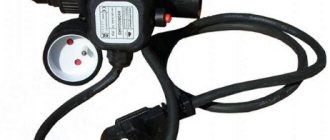
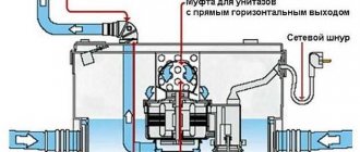
The operation of modern household and industrial appliances largely depends on the correct and uninterrupted operation of electronic devices. In many ways, this state of affairs suits us, however, as soon as a failure occurs, the normal rhythm of life turns into a complete hassle. But in principle, nothing bad happens, just one of the components fails.
It is precisely these components of modern household appliances that include a water flow sensor. A simple device that is equipped with gas hot water boilers, autonomous water supply systems, irrigation systems, and well pumps.
Like all electronic components, the water flow sensor also has principles by which it works. In principle, everything is simple here, the whole point of its work is to signal whether there is water movement or not. The sensor is installed, for example, in a pipe. When the tap is closed, there is no movement of water, but as soon as the tap opens, the water begins to move and the sensor is triggered, the contacts close and the signal goes to the control board.
True, it is necessary to immediately point out that the sensor is pre-set to a certain sensitivity threshold - this is when the water movement must reach a certain point, for example, 1.7 liters per minute. Then the sensor will turn on, and will continue to work until the water supply speed decreases below the mark, and then the contacts will open and the control board will no longer receive the signal.
Flow sensor malfunctions
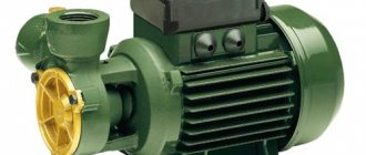
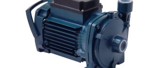
Design and principle of operation of a rotary pump
Common malfunctions that may occur during operation:
- The DHW mode does not start, the equipment is unstable. To make sure that it is the regulator that has failed, you need to take a multimeter and measure the resistance. If it is approximately 2.5 kOhm, then according to the table this indicator should be achieved when heated to 60 degrees. But if the device is cold, then the problem is definitely in the water flow sensor. The regulator will “say” that the water is already heated and additional temperature is not needed. To fix the problem, you will have to completely replace the failed sensor. But we must not forget that it has direct contact with water and before removal it is necessary to drain all the water from the boiler (Baksi or other companies) and shut off its supply.
- If error No. 201 appears on the indicator, this means that there is a break or damage to the wires that are connected to the regulator. For the regulator to work normally, you need to restore its original position.
- Error No. 202 - short circuit. In this case, you need to check the device itself or the wires that are connected to it.
Gas boiler and its relay equipment
The water flow sensor gives the gas boiler two important functions:
- Indicates that hot water is being drawn in, after which the control board changes the heating mode to the hot water supply mode, which provides heating.
- The sensor controls the combustion of the boiler flame by analyzing the intensity of the water flow. Larger water intake requires a stronger flame, as more energy is required for heating.
A water flow sensor for a gas boiler provides water heating and heating functions. The installation is suitable for a circuit supplying tap water and responds to water intake when the tap is opened.
Possible problems during operation:
- The water heating mode does not turn on or works intermittently. You can understand that the fault lies in the sensor after measuring the resistance with a multimeter. 2.5 kOhm is achieved at a temperature of 60 degrees. If the device is completely cold, then there is definitely a problem with the flow sensor. The problem is solved by a complete replacement, but it is important to remember the need to shut off the water.
- Closure. The reason may be incorrect assembly of the device itself and incorrect connection of the wires.
Different brands of boilers display an error code on the display. This information is usually in the owner's manual. When identifying a problem in flow sensors, the solution can be done independently with certain skills or with the help of specialists.
What is and why do you need a water flow switch?
Generator voltage regulator relay: diagram, principle of operation
In household water supply systems, the action of a pumping station without water quite often occurs and threatens an accident. This problem is called “dry running”.
As a rule, the liquid cools and lubricates the elements of the system, thereby ensuring its normal operation. Even short-term dry operation leads to deformation of individual parts, overheating and failure of the equipment motor. Negative consequences apply to both surface and deep-well pump models.
Dry running occurs for various reasons:
- incorrect choice of pump capacity;
- unsuccessful installation;
- violation of the integrity of the water pipe;
- low fluid pressure and lack of control over its level, for which a pressure switch is used;
- accumulated debris in the pumping pipe.
An automatic sensor is necessary in order to completely protect the device from the threats posed by a lack of water. It measures, controls and maintains constant water flow parameters.
Pumping equipment equipped with a sensor has many advantages. It lasts longer, breaks down less often, and uses energy more economically. There are also relay models for boilers
Possible faults
Sometimes it may require repairs using water sensors if, for example, your control unit does not respond to a wireless type sensor, and then you need to check the power supply, and then the permissible distance to the (wireless) receiver. If there is still a malfunction of the wired product, you should first check all the cables for breaks, and also find out the tightness of the connection of the plugs and the controller. Malfunctions can occur due to plaque and contamination, and for this reason, devices should be wiped with a damp cloth at least once a month.
If there are no fault signals on the sensor, and the console simply does not register them, then the problem lies in the control unit. According to the instructions, the maximum permitted distance of devices from the control center should be taken into account.
Check all power supplies, mains voltage, batteries, and in such cases you should check:
- If there is contact with moisture, the alarm indicator on the block and sensor should light up, and the electric drive of the faucet will not operate.
- Recorders do not react when wetted with water.
If voltage appears when the sensors are wetted with liquid, but the tap does not turn off the water, you should disconnect the wires from the electric drive of the tap, and then check the voltage on them as well. If it appears, then the fault is hidden in the crane servo drive. If there is no voltage, then you should ring the cable for a break, and to do this, you should short-circuit both ends at one end of the cable, and ring back at the other.
Where are they used?
Screw pump: principle of operation, scope and design features
Flow sensors are used in devices where control of the water supply system to an apartment or private house is necessary. By installing this type of equipment on a gas boiler, you can significantly reduce your monthly payment, and the heat generator will also become much safer to use.
For gas boilers
There is a water flow regulator in all boilers (Buderus and other models). Thanks to the device, the heat generator can work as a device for heating a home and heating water.
The gas boiler water pressure sensor is mounted on the pipeline. Once installed, it begins to respond to flow as soon as the hot tap is opened.
The regulator transmits a signal to a special board installed inside the boiler. After this, the circulation pump automatically starts and the pressure in the gas injectors decreases. As a result, the water circulation valve closes. After this, the water heating nozzles turn on, and the liquid begins to warm up in the heat exchanger. After closing the valve, the mounted sensor for the gas boiler records this action and transmits the corresponding signal to the board.
For pumps
In many private houses, an autonomous water supply system is installed. This is necessary if there is often low pressure on the site and the owner wants his yard to be independent of the centralized water supply. The equipment is installed so that the water pressure in the house always remains at a high level.
The system includes:
- special pump;
- a tank where water is poured;
- control system.
You can connect various household appliances to the pump, for example, dishwashers or washing machines. In this case, the regulator is necessary for timely activation of the pump, ensuring a stable water supply.
And it doesn’t matter whether the wash has started, the tap is open in the kitchen, or water is draining from the toilet tank - the regulator performs the same functions for any type of household equipment connected to the system.
Also, the owners of the living space in question often connect the sensor in question to automatic watering in the country or in a private house. Here the device not only performs the opening function, it regulates the amount of water that should be consumed at a time.
This function is very useful if dosed watering is used so as not to over-moisten the soil. For stable operation, the flow regulator is mounted to the central pipeline, and it transmits all information to the system control panel.
Device classification
- By the number of secondary protective devices at the facility (emergency shut-off valves with electromagnetic drive). Leakage sensors should not shut off all water supplies if shut-off systems are distributed among consumers. Only the line on which a leak is detected is localized.
- According to the method of submitting information about a water supply (heating system) accident. Local alarm assumes that people are present at the site. Remotely transmitted information is organized taking into account the prompt arrival of the owner or repair team. Otherwise, it is useless.
- Notification method: local sound or light alarm (on each sensor), or output of information to a single remote control.
- Protection against false positives. Typically, finely tuned sensors perform more efficiently.
- Mechanical or electrical protection. An example of mechanics is the Aqua Stop system on the supply hoses of washing machines. There is no alarm on such devices, the scope of application is limited. Self-production is impossible.
Sensor types
Today, the most popular and advanced water flow devices are reed switch relays and Hall sensors.
Description:
- A flow meter or Hall sensor is a small turbine with a magnet. As soon as the turbine begins to rotate, the magnet creates a field and generates electrical pulses that are transmitted to the boiler board (for example, Ferroli).
- The reed switch regulator also uses magnetism. A float magnet is installed inside the chamber. As soon as the water pressure increases, the float moves and begins to act on the reed switch (several magnetic plates that move apart under the influence of the float).
Types of level sensors
One of the conditions for successful operation of the sensor is the high sensitivity of the sensor; the higher the better, the more accurately it is possible to read the monitored water parameter. Therefore, as the quantity measured by the sensor, they try to choose the one that changes the most during the measurement time.
Today, there are about two dozen different methods and methods for measuring the mechanical characteristics of water, but they are all used to obtain information:
- The height of the water column in the container or tank;
- The speed of flow or flow of water;
- The fact of the presence or absence of water in a closed container, reservoir, pipe or heat exchanger.
Of course, industrial sensors can be quite complex in design, but the operating principles used in them are the same as in household, gardening or automotive equipment.
Float type overflow sensor
The simplest way to measure water level is using a simple mechanical design consisting of a sealed float, an oscillating lever or rocker and a shut-off valve. In this case, the sensor is the float, the ballast is the spring and the float weight, and the valve itself is the actuator.
In all float systems, the sensor or float is adjusted to a specific actuation height. The water rising in the tank to the control level raises the float and opens the valve.
The float system can be equipped with an electrical actuator. For example, a magnet insert is installed inside a float sensor; when the water rises to the operating level, the magnetic field causes the vacuum reed switch to close the contacts, and thereby turns on or off the electrical circuit.
The float sensor can also be implemented in a free design, as, for example, in submersible pumps. In this case, the reed switch does not close under the influence of the magnetic field of the liner, but only due to the pressure difference inside the pump housing and at the level of the float. Today, a magnetic float sensor with an electric actuator relay is considered one of the safest and most reliable options for monitoring liquid levels.
Ultrasonic sensor
The design of the water sensor provides for the presence of two devices - an ultrasound source and a signal receiver. The sound wave is directed to the surface of the water, reflected and returned to the sensor receiver.
At first glance, the idea of using ultrasound to make a sensor for controlling the level or speed of water does not look very good. An ultrasonic wave can be reflected from the walls of the tank, refracted and interfere with the operation of the receiving sensor, and in addition, complex electronic equipment will be required.
In fact, an ultrasonic sensor for measuring the level of water or any other liquid is placed in a box slightly larger than a pack of cigarettes, and using ultrasound as a sensor provides certain advantages:
- The ability to measure the level and even the speed of water at any temperature, in conditions of vibration or movement;
- The ultrasonic sensor can measure the distance from the sensor to the water surface even in heavily polluted conditions with variable liquid levels.
In addition, the sensor can measure water levels located at significant depths, with measurement accuracy reaching 1-2 cm for every 10 m of height.
Electrode principle of water control
The fact that water is electrically conductive has been successfully used to make contact liquid level sensors. Structurally, the system consists of several electrodes installed in a container at different heights and connected into one electrical circuit.
As the container is filled with water, the liquid sequentially closes a pair of contacts, which turns on the pump control relay circuit. As a rule, the water sensor has two or three electrodes, so the measurement of water flow is too differentiated. The sensor only signals when the minimum level is reached and starts the pump motor, or when the tank is completely filled and turns it off, so such systems are used to control reserve or irrigation water tanks.
Capacitive type water sensor
The condenser or capacitive type of sensor is used to measure the water level in narrow and deep containers, this can be a well or a borehole. Using a capacitive sensor, you can determine the height of the water column in a well with an accuracy of ten centimeters.
The sensor design consists of two coaxial electrodes, actually a pipe and an internal metal electrode, immersed in the wellbore. Water fills part of the internal space of the system, thereby changing its capacity. Using a connected electronic circuit and a quartz oscillation coil, you can accurately determine the sensor's capacitance and the amount of water in the well.
Radar meter
A wave or radar sensor is used to work in the most difficult conditions, for example, if you need to measure the level or volume of liquid in a tank, an open reservoir, or an asymmetrical and irregularly shaped well.
The principle of operation is no different from an ultrasonic device, and the use of an electrical pulse makes it possible to perform measurements with great accuracy.
Hydrostatic sensor option
One of the options for a hydrostatic sensor is shown in the diagram.
For your information! A similar sensor is used in washing machines and boilers, where it is very important to control the height of the water column inside the tank.
The hydrostatic sensor is a box with an elastic spring-loaded membrane that divides the sensor body into two compartments. One of the sections is connected by a durable polyethylene tube to a fitting soldered into the bottom of the tank.
The pressure of the water column is transmitted through the tube to the membrane and causes the contacts of the starting relay to close; most often, a pair is used to start the actuator - a magnetic insert and a reed switch.
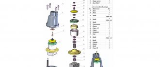
Design and principle of operation
The operating principle of the flow switch is based on the mechanical effect of the water flow in the pipeline on the sensor that controls the electronic circuit for turning on and off the electric pump. Relays have different operating principles and, depending on the design of the sensor, are divided into several types.
Petal relays
One of the most common types, the main elements are a petal sensor with a magnet located in the water flow and a reed switch placed in the device body and securely insulated.
As water flows through the pipeline, the vertically located petal sensor rotates along its axis and deviates from the vertical position, bringing the built-in magnet closer to the reed switch. Its contacts inside the cylinder are closed and the pump is connected to a source of electricity through a triac (double symmetrical thyristor).
If there is no water in the pipeline, the petal returns to its original position, moving the magnet away from the reed switch and thereby opening its contacts.
This leads to the cessation of supply voltage to the pump through the semistor, as a result of which it turns off.
Water flow control devices
In any situation that causes the pump to run dry, there is insufficient or no water flow. There are devices that monitor this situation - relays and water flow controllers. Flow relays or sensors are electromechanical devices, controllers are electronic.
Flow relays (sensors)
There are two types of flow sensors - petal and turbine. Petal has a flexible plate that is located in the pipeline. In the absence of water flow, the plate deviates from its normal state, contacts are activated, turning off the power to the pump.
Turbine flow sensors are somewhat more complicated. The basis of the device is a small turbine with an electromagnet in the rotor. When there is a flow of water or gas, the turbine rotates, creating an electromagnetic field, which is converted into electromagnetic pulses read by the sensor. This sensor, depending on the number of pulses, turns on/off the power to the pump.
Flow controllers
Basically, these are devices that combine two functions: dry-running protection and a water pressure switch. In addition to these features, some models may have a built-in pressure gauge and check valve. These devices are also called electronic pressure switches. These devices cannot be called cheap, but they provide high-quality protection, serving several parameters at once, ensuring the required pressure in the system, turning off the equipment when there is insufficient water flow.
| Name | Functions | Dry running protection parameters | Connection dimensions | Manufacturer country | Price |
| BRIO 2000M Italtecnica | Pressure switch + flow sensor | 7-15 sec | 1″ (25 mm) | Italy | 45$ |
| AQUAROBOT TURBIPRESS | Pressure switch + flow switch | 0.5 l/min | 1″ (25 mm) | 75$ | |
| AL-KO | Pressure switch + check valve + dry-running protection | 45 sec | 1″ (25 mm) | Germany | 68$ |
| Gilex automation unit | Pressure switch + idle protection + pressure gauge | 1″ (25 mm) | Russia | 38$ | |
| Aquario automation unit | Pressure switch + idle protection + pressure gauge + check valve | 1″ (25 mm) | Italy | 50$ |
In the case of using an automation unit, the hydraulic accumulator is an extra device. The system works perfectly when a flow appears - the opening of a tap, the activation of household appliances, etc. But this is if the pressure reserve is small. If the gap is large, both a HA and a pressure switch are needed. The fact is that the pump shutdown limit in the automation unit is not adjustable. The pump will turn off only when it has created maximum pressure. If it is taken with a large headroom, it can create excess pressure (optimal - no more than 3-4 atm, anything higher leads to premature wear of the system). Therefore, after the automation unit they install a pressure switch and a hydraulic accumulator. This scheme makes it possible to regulate the pressure at which the pump turns off.
Connecting and adjusting the sensor
The efficiency of the sensor that monitors the flow of water and controls the operation of pumping equipment largely depends on the correct installation of this device. It should be borne in mind that such a sensor, regardless of the type and purpose of the pipeline, can only be installed in horizontal sections. In this case, it is necessary to ensure that the sensor membrane is located strictly in a vertical position.
When installing a liquid flow sensor, it is connected to the drain part of the pipeline using a threaded coupling. In this case, the distance at which such a device should be located from the pipe itself cannot be less than 55 mm.
Flow sensor installation diagram
On the housing of factory water flow sensors there is always an arrow that indicates in which direction the liquid should move through them. When installing the sensor on the pipeline, you must ensure that this arrow coincides with the direction of water movement. If the sensor is installed in a system through which heavily contaminated liquid is transported, filters must be placed in front of it for the correct operation of such a device.
Electrical connection diagram
Despite the fact that fluid flow sensors are supplied from manufacturing plants with already adjusted parameters, independent adjustment must be performed periodically. For this purpose, special bolts are provided in the design of the sensors. With the help of the latter, the degree of compression of the springs is increased or decreased, setting the level of pressure at which this device will operate.
Leaf type flow sensor adjustment controls
So, to adjust the water flow sensor with your own hands, you need to perform the following steps:
- drain the water from the pipeline system and make sure that the pressure has reached zero;
- turn on the pump and start filling the system with water;
- when the pump is turned off, which occurs due to a signal from the sensor, record the value of the liquid pressure;
- Draining the liquid from the system again, record the pressure value of its flow at which the pump will turn on;
- by removing the sensor cover and using a special bolt, adjust the degree of compression of the large-diameter spring (this way you will set the minimum pressure level at which the device will operate and the pump will turn on; it should be borne in mind that compression of such a spring increases the pressure level, and weakening reduces it);
- Having filled the system again with water and starting to drain it, check whether the sensor is adjusted correctly and whether it turns off the pump at the required pressure level (if the device is adjusted incorrectly, the entire procedure described above should be repeated);
- by changing the degree of compression of a spring of small diameter, set the maximum pressure level at which the pump will turn off (the difference between the sensor response thresholds increases when such a spring is compressed and decreases when it is weakened);
- after adjusting the degree of compression of a small-diameter spring, check that this procedure is performed correctly by starting to fill the system with water and recording the pressure value at which the pump turns off (if this adjustment is performed incorrectly, it should also be repeated until the desired result is achieved).
General information
Operating principle
As soon as the sensitive elements are able to detect the ingress of water, the sensor will react as follows:
- Sound or light notification.
- Triggering of an alarm and transmission of signals to an electric drive in order to shut off the water.
Please note that if the sensor was installed incorrectly (i.e. at a large distance from the floor surface), there is a risk of flooding.
Additional equipment is required to automatically shut off the water supply: when the control unit receives a signal, it begins to supply voltage to the tap drive, and the pipe is blocked. After the leak is fixed, the gadget can be unlocked from the console.
Types of water sensors
Types according to operating conditions:
- Industrial type.
- Household type.
By type of power supply:
- Wired - powered from the network and the power supply.
- Autonomous - batteries act as power sources.
Varieties of design by form factor:
- A cable that connects to the power supply.
- Corpus.
There are also sensitive elements that only have an alarm or are connected to a control unit, electric valves and shut-off valves.
Sensor device
In the standard set you can find the following components:
- Water sensors (wireless and wired).
- Control unit or controller.
- Cranes with electric drive (if provided).
The tasks of a sensor for the presence of water in pipes without actuators are a signal about flooding, and therefore they are in no way connected with the various control units of electric drives. The device looks like a plastic head that has reacting elements. It is connected to a small alarm and power supply with several batteries. Other devices have a plastic or metal case that has indication elements or operates without a bottom. There are other products that look like a cable (cord) laid on the floor that is connected to an independent power supply.
Inside the device body there are such elements as:
- Batteries (which act as an autonomous power source).
- A node that distributes radio signals.
- Elements for signaling.
- Electrodes are made in the form of pads or plastic that conduct current.
- A controller that records changes in resistance between the plates.
Batteries, i.e. our power supply and alarm are located on a separate control unit. They are made in the form of a plastic box, which in appearance resembles a switch or a flat box with separate cable outlets. The device with the contacts faces down, and the body is made in such a way that particles of water do not accidentally fall on them. The contact pads are raised above the floor by 0.1-0.2 cm due to small legs or features of the body shape. This will enable the device to operate, but only when the water level exceeds certain specified height parameters.
Operation
The purpose of the water sensor is to notify about water leaks or as part of a security alarm, as well as to generate a signal in order to shut off pipes and mechanisms that supply water.
Functions of water sensors and other similar equipment:
Analysis of schematic elements- Using channels from mobile communications to notify the user.
- Prompt opening and closing of water supply.
- Expansion of the scheme, as well as the use of new elements for addition.
- Separate notification, as well as control using groups of drives/individually, and different sensors are used.
A separate notification method is used to separate heating leaks from standard plumbing leaks.
The device will help to respond in a timely manner in common emergency situations:
- Leaking drain under bathtub and sink.
- Alarm for broken water hoses, drain pipes from washing machines and dishwashers.
- Leakage at the junction of water pipes, or pipelines from household appliances.
- Water overflowing through the sink due to a clogged drain.
- Breaks and cracks in pipes.
Now it would not be superfluous to talk about the advantages and disadvantages of water presence sensors.
Advantages and disadvantages
Automatically turning off the water two seconds after a leak is detected by the system greatly increases the safety of operating water appliances and other similar equipment.
Such reliable devices have protection against false alarms, so as not to be triggered by an accidentally spilled drop of water. Wireless devices for communication with an element such as a controller are capable of emitting a radio signal with a frequency of 400-500 MHz. One of their advantages is that such devices can easily be placed throughout the room without carrying out full installation work, laying cables and other elements.
With their power source – standard batteries – the products can operate from two to four years without replacement. Among the disadvantages, it should be noted that direct contact with water is required - if the installation location for contact with water is incorrectly selected (when the choice of floor level is not taken into account or there are surface unevenness), the liquid will not immediately get onto the device.
Design features
The main tasks that water flow control sensors installed in domestic pipelines solve are to turn off pumping equipment at a time when there is no liquid in the system or its flow pressure exceeds the standard value, and turn it on again when the pressure drops. An effective solution to these important problems is provided by the sensor design, which consists of the following elements:
- a pipe through which water enters the sensor;
- a membrane that makes up one of the walls of the inner chamber of the sensor;
- a reed switch that provides closing and opening of the pump power supply circuit;
- two springs of different diameters (the degree of their compression regulates the pressure of the fluid flow, at which the water flow switch for the pump will operate).
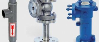
Main components of an industrial flow sensor
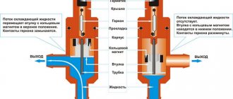
The device of the above-described design works as follows:
- Entering the inner chamber of the sensor, the water flow puts pressure on the membrane, displacing it.
- The magnetic element fixed on the back side of the membrane, when it is displaced, approaches the reed switch, which leads to the closure of its contacts and the pump being turned on.
- If the pressure of the water flow passing through the sensor drops, the membrane returns to its original position, the magnet moves away from the switch, its contacts open, and accordingly, the pumping unit is turned off.
The operating principle of a flow sensor based on a permanent magnet and a reed switch
Sensors that monitor water flow are installed quite simply in pipeline systems for various purposes.
The main thing is to choose the right device, paying attention to its operating parameters and characteristics of the pumping equipment
Device selection criteria
When choosing equipment that controls the force of water flow, you should carefully study its technical characteristics.
Particular attention should be paid to the operating temperature and pressure range for which it is designed, the diameter of the threads and mounting holes, the protection class, and application nuances. It is also important to clarify what materials the product is made from.
Experts consider devices made of brass, stainless steel, and aluminum to be the most reliable and durable. These materials protect the structure from the critical consequences of a common phenomenon in water supply systems - water hammer.
When considering different modifications of the relay, it makes sense to purchase a version made of metal. The housing and working components of such devices are highly durable.
This fact allows the equipment to withstand serious loads for a long time that arise due to significant pressure in the water supply from the liquid passing through the sensor.
The pressure value at which the relay operates must correspond to the power of the installed pump. The parameters of the water flow circulating through the pipeline depend on this characteristic.
It is advisable to choose a device with two springs that controls the operation of the pumping station according to certain lower and upper pressure marks.
The operating temperature range of the sensor directly indicates its possible area of application. For example, models with a high limit temperature are designed for hot water supply circuits and heating systems. For cold water pipelines, a range of up to 60 degrees is sufficient
Another important criterion that deserves special mention is the climatic conditions necessary for the operation of the product. This refers to the recommended air temperature and humidity level that the device needs to provide in order for it to perform at its best.
The maximum permissible load for a particular device is determined by the protection class specified in the technical specifications.
When purchasing a flow sensor, you should check the thread diameter and the dimensions of the mounting holes in the equipment: they must fit perfectly with the pipeline elements. The correctness and accuracy of further installation, as well as the efficiency of the relay after installation, depend on this.
Device connection diagram
The operating efficiency of the relay greatly depends on its correct installation. It must be remembered that the device can only be installed on those sections of the pipeline that are located horizontally. In this case, you will need to ensure that the sensor membrane is in a vertical position. The correct relay connection diagram looks like this:
During installation, the sensor must be connected to the drain part of the pipe using a threaded connection. The distance at which the relay should be located from the pipe should be more than 5.5 cm.
There is an arrow on the body of the device indicating the direction of liquid circulation. When installing the device, you need to make sure that this arrow coincides with the direction of water flow in the system. If dirty water is used for domestic purposes, then cleaning filters should be installed in front of the sensor.
Device installation
The selected water flow sensor must match the technical characteristics and parameters of the pump and pipeline.
It is optimal to carry out the installation before the first start-up of the water supply system. This ensures the prevention of faults and their consequences.
Installation steps include cutting in the sensor and connecting the electronics.
Installation is carried out in the direction corresponding to the arrow indicated on the relay body (shows the direction of water flow). The device is installed on a tee fitting that cuts into the pipe. The liquid is first drained from the pipeline. Location on the pipeline leaving the pump is recommended.
The protection is installed together with the pressure gauge according to the scheme recommended by the manufacturer.
To ensure a seal, the threads are sealed with plumber's tape or flax. Winding is carried out clockwise.
When contaminated water enters through a pipeline, the optimal solution is to install a filter in front of the sensor.
A break is made in the pump power cable, and a sensor is connected to the resulting section. Electrical connections must be made according to the diagram indicated on the accompanying documentation.
General installation rules
Particular attention is paid to screwing carefully to avoid damaging the relay. The recommended distance between the device and the pipeline is 5.5 centimeters.
Rotary relays and flow type sensors
Rotary sensors are mainly used to measure and control fluid flow. Structurally, they are made in the form of a paddle wheel rotating in a fluid flow; its rotation speed is recorded by sensors. The electronic circuit allows for analog, frequency or discrete control of the operation of the equipment.
Piston devices
The piston is placed in the valve seat and, under the influence of water pressure, moves in the vertical direction to a height proportional to the force of the flow. A permanent magnet mounted on the piston approaches the reed switch and the contacts in it close. Piston devices can be installed on horizontal and vertical pipelines thanks to the built-in return spring, which returns the piston to its original position in the absence of flow.
appearance
Why are water sensors used?
Based on practice, it is noted that the main cause of pump failures is their overheating due to operation in the absence of fluid flow. This is where the use of flow sensors lies.
This occurs in the following situations:
For constant monitoring of productive operation, the pump is equipped with a flow switch. Control devices are used to identify fluid intake, speed, and measure flow rates.
Current sensors are highly sensitive and respond to a small flow of liquid. Can be used for different liquids (aggressive and non-aggressive).
Installation of the device is not required in circumstances where:
In all other cases, to extend the life of the pump and ease of use, a water flow switch is used.
Installation of a relay on a pump or station
If installation of the device is required, the work can be done independently, especially if you have to be away and there is no way to constantly monitor the operation of the pumping equipment.
When you do not need to install a relay:
- if water is pumped from a well with a large volume, that is, liquid reserves are not limited, and the pump power is minimal;
- It is possible to turn off the installation when the water level drops.
Equipment installation rules:
It is important to monitor the membrane - the part must take a vertical position. Installation is carried out to the drain pipeline section using threaded couplings. There is a special slot for this. Before starting work, the threads are sealed with linen or other plumbing thread
Winding the thread towards the end clockwise will increase the reliability of fastening and fixation. Factory sensors are equipped with an arrow drawn on the body - this is the direction of flow, which must match during installation. When installing relays in water supply pipelines with dirt particles, cleaning filters are first installed. It is better to mount them next to the sensor to extend the service life of the device.
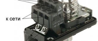
Testing of the installed device is carried out with connection to the power supply:
- the free ends of the contacts are connected to the wire core;
- grounding is mounted to the screw;
- the device is connected by connecting the device with a wire (watch the color of the corresponding wires);
- system functionality is checked.
Self-adjustment of the water movement sensor
The factory device is equipped with bolts, by tightening or loosening which you can increase/decrease the spring compression. Bolts will be required if you need to install the sensor at a certain pressure level at which the mechanism is triggered.
Algorithm of actions:
- drain the liquid from the system;
- wait until the pressure mark reaches zero;
- start the pumping unit;
- run the water back in the slowest mode;
- remember the flow pressure indicator when the pump relay is turned off;
- drain the liquid again, recording the indicators when the system starts operating.
Now you need to open the relay, use the bolt to adjust the compression level of the larger spring - this will trigger the device when the pump starts. The adjustment is made taking into account that strong compression will increase the degree of pressure, and weak compression will decrease it. Then the compression force of the smaller spring is adjusted - here the limit of the maximum pressure level is set, upon reaching which the relay will automatically turn off the pump.
As soon as the adjustment is completed, start the system, evaluate the results of the work when filling the pipeline and draining the flow. If adjustment changes are necessary, repeat the procedure. Checking functionality and adjusting operating parameters is an annual procedure that extends the life of the device.
Recommendations for installation and configuration
Liquid flow relays are installed for devices that require constant control and compliance with a certain operating mode. Often they are equipped with equipment at the production stage. However, there are also circumstances when a separate installation of the sensor is required.
Rules for installing relays in the system
Installing a safety device that detects the presence or absence of water flow in the system is a reasonable step in cases where it is not possible to be present while the pumping equipment is operating.
It is not required only in two cases:
The device is installed on horizontal sections of the pipeline. In this case, you need to ensure that the membrane assumes a stable vertical position.
The device is mounted to the drain pipeline using a threaded coupling. Usually a special socket is provided for this.
Before you start directly screwing the device, it is advisable to seal the threads well with flax or thread, sold in specialized departments.
It is better to wind it clockwise towards the end. This method of fastening increases the reliability of fixation.
When installing a factory sensor, you need to focus on the arrow shown on the body. The direction indicated on it must coincide with the direction of flow of the liquid passing through the device.
If contaminated water is transported through the pipeline, it is recommended to install cleaning filters, placing them near the sensor. Such a move will ensure the correct operation of the product.
At the final stage of installation work, the dry-running relay is connected to the electrical network:
After connecting to the network, all that remains is to check the functionality of the system. The fact that the device is ready for full operation will be indicated by an increase in pressure marks on the pressure gauge and the automatic shutdown of the pump when the limit value is exceeded.
Self-adjustment procedure
For adjustment, the sensor has special bolts. By loosening or tightening them, you can reduce or increase the compression force of the spring.
This sets the pressure level at which the device will operate.
In most cases, setting up automatic equipment is not difficult.
It is advisable to adhere to the following algorithm:
Having completed all the described manipulations, you should make sure that the adjustments made are correct. To do this, the pipeline is filled with liquid and then drained, assessing the sensor’s response when the set values are reached.
If the test result is unsatisfactory, the procedure is repeated.
To ensure that the pipeline through which the liquid passes works properly and stably, regular annual checks of the flow sensors are carried out. If necessary, the operating parameters are adjusted.
Review of famous manufacturers and prices
Several models in the $30-40 price category are considered the most famous and reliable:
- Genyo Lowara Genyo 8A. Manufacturer – Poland. The main direction of the company is the production of electronic equipment for control systems. The relay is designed for use in domestic water supply systems and is characterized by high quality and long service life. By monitoring the flow pressure in the pipes, the sensor starts the pumping system at a water flow rate of 1.6 l/minute. The unit requires an electrical connection and consumes 2.4 kW/hour. Operating temperature +5..+60 C.
- Grundfos UPA 120. Manufacturer's plants are located in Romania and China. The device has small dimensions, is convenient to install and is indicated for individual water supply systems. That is, it can be used both in private buildings and apartments. The device starts up at a liquid flow rate of 1.5 l/minute, completely preventing the functionality of the system at idle. The extreme operating temperature is +60 C.
The models have been tested and adapted to domestic operating conditions. Numerous reviews characterize metering sensors as durable and practical units at an affordable price.
Review of products from the best manufacturers
Companies whose product range includes double-circuit boilers offer users highly specialized additional equipment, among which flow sensors occupy a special niche.
Electrolux products are compatible with the GCB 24 X FI and GCB 24 XI series, their weight is only 150 g, the maximum operating pressure is 1.5 Pa. The dimensions of the devices are compact - 40x115x45 mm, the pressure range does not exceed 3 bar, the upper limit of permissible environmental humidity is 70%.
Viessmann Vitopend WH1D
The Visman flow sensor is installed in the gas boiler on the left side of the hydraulic unit. This element is necessary to control the parameters and performance of the hot water flow. The model is designed for the Vitopend and Vitopend 100 series.
Ariston GENUS CLAS B 24
The Genus Ariston sensor is necessary to coordinate water heating with a gas boiler. When the flow occurs, a signal is sent to the electronic board of the latter, as a result the equipment switches to operating mode. A magnetic float is enclosed in a composite plastic case; it acts on a reed switch, the contacts of which close (the boiler begins producing hot water) or open (heating is provided).
Grundfos UPA 120
The device protects the pump from idling and is implemented in individual water supply systems. The automation functionality requires ensuring a stable fluid flow of at least 90-120 l/hour. The device protection class is IP65, the power consumption of this budget model does not exceed 2.2 kW. The operating temperature limits are kept in the positive range - from 5 to 60°C, 8 A is an indicator of the maximum current consumption.
Widely used in domestic water supply systems, the basis for its operation is the actual water consumption. The sensor is capable of monitoring the pressure level in the water supply. The pump starts only when the monthly water flow reaches 1.5 liters. The degree of protection of the unit is IP65, the operating voltage is in the range of 220-240 V. Power consumption is kept at around 2.4 kW.
Immergas 1.028570
Initially, the model was designed for use with boilers of the same brand; it is compatible with double-circuit gas equipment of the Victrix 26, Mini 24 3 E, Major Eolo 24 4E series. The device can be used with boilers of turbocharged and chimney versions. The sensor is enclosed in a plastic housing and equipped with a threaded element for integration into the system. An additional option is the ability to obtain hot water at the outlet that has a stable temperature.
A significant segment of water flow sensors for boilers is supplied complete with heating equipment, so the need for their installation arises only in the event of a breakdown, when you have to think about a commensurate replacement. A rare case when a separate installation of the device is planned is the need to increase the pressure of the liquid supplied to the system. A similar situation occurs if the central water supply is characterized by low pressure, barely reaching the needs of the boiler. In order for a gas appliance to be able to provide the proper quality of hot water supply, it must deal with good pressure.
To solve this problem, install an additional circulation pump and equip it with a water flow sensor (the components must be introduced into the system in this order). As water begins to flow, the device activates the pump, which leads to an increase in pressure.
Homemade models are made from a chamber that will be used in conjunction with three horizontally mounted plates
It is important that the latter do not contact each other and do not touch the flask
For the simplest modifications, the introduction of one float is sufficient. The fitting should be mounted in tandem with two adapters, the maximum permissible valve pressure is 5 Pa.
Effective operation of pumping equipment is the key to uninterrupted water supply and functioning of the heating system in a private home. If you want to enjoy the benefits of civilization every day, you must make every effort to set it up correctly.
The solution to this problem includes a wide range of work, the main one being the installation of additional equipment that will help to clearly monitor possible failures in the system and prevent pump failure.
The most popular and useful in everyday life are such auxiliary devices as: a temperature sensor, as well as a water flow sensor. It is the properties and operational features of the latter device that will be discussed in this article.
How to set pressure using a flow switch
Briefly - for 5 seconds. – press button “1”:
In this case, the “accident” lamp should blink red. This is where we entered programming mode. Now we turn on the pump, and as it works, it builds up pressure. It is clear that all taps in the house must be closed. We look at the pressure on the pressure gauge. For example, we need the water supply to be 2 atm, so we wait for the pump to build up this pressure. As the arrow on the pressure gauge shows the required pressure, press button “1” again. The pump will turn off.
We press the “2” button, thereby “driving” into the relay’s memory that at this pressure the pump should turn off.
Now we are programming the lower limit. To do this, open any tap so that the pressure begins to drop. When the pressure gauge shows the lower pressure we need, press button “1” again and the pump will turn on. By pressing button “2” we “drive” the relay into the head so that at this pressure the pump must be turned on.
Water leakage sensor
Already from the name it becomes clear that we are talking about a device that detects the presence of water leaks from water supply lines. The operating principle of the device resembles an electrode system. Inside the plastic box, one or more pairs of electrodes are installed in a special pocket. In the event of an accident, water accumulating on the floor flows into the pocket and closes the contacts. The electronic circuit is activated, and based on the sensor signal, the electrically driven ball valves come into operation.
It is clear that the sensor itself is useless if it is used without a control system and automatic water shutoffs installed at the entrance to the house or on one of the water supply branches.
As an example, one of the most popular protection systems is the Neptune water leak sensor. The system includes three main blocks:
- The Neptune leak sensor itself is available in a wired or wireless version; the kit usually includes three separate sensors;
- Ball valve with electric drive, made in Italy, two pieces;
- Control unit "Neptune Base".
The most valuable part of the kit is the automatic taps; they are produced for installation on half-inch and inch pipe threads. The design can withstand pressure up to 40 Atm., and the Italian quality of the drive guarantees at least 100 thousand opening-closing cycles.
The sensor itself looks like two brass plates in a box, to which a low voltage voltage is applied with a very high input resistance; when the sensor is shorted, the current is limited to 50 mA. The design itself is made according to the IP67 protocol, therefore it is absolutely safe for humans.
Installation of wireless water leakage sensors
In the Neptune system, the sensor can be removed from the control unit at a distance of more than 50 m. In more advanced NEPTUN PROW+ wireless systems, instead of a wire system, water leakage sensors equipped with a WF module are used.
The control unit is equipped with a channel protected from interference and moisture, and an on/off system for ball valves. It is believed that no interference or random drops of moisture or condensation affect the operation of the sensors.
Boxes with a leakage sensor are installed no more than 2 m away from the pipes; the sensors cannot be shielded by metal plumbing fixtures or furniture.
Wireless water leak sensor
The design of a wireless meter is more complex than a conventional two-electrode version with a wired connection. There is a controller installed inside that continuously compares the current flowing between the electrodes with a reference value stored in memory. In this case, the reference value “dry floor” can be adjusted according to your own choice.
A very convenient solution, considering that the humidity level in the bathroom can be very high, and regularly occurring condensation can lead to false alarms.
As soon as the controller determines the level corresponding to flooding, the water control device sends an alarm signal to the base unit. The most advanced models are capable of duplicating a command via SMS message via GSM channel.
Installation features
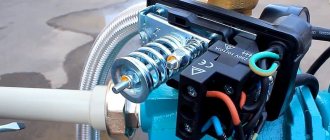
Paddle switches are mounted either at the pump inlet or at the valve inlet. Their task is to record the initial entry of liquid into the working chamber, and therefore contact with it must be detected first of all on the relay itself.
Pressure control units are installed only with the help of specialists, as they require adjustment. They are installed in the same way as the petals, by connecting the inlet to the pumping device. However, unlike conventional petals, pressure switches are almost always used in conjunction with pumping stations.
Thermal relays are rarely used separately, since the thing is too expensive. It will most likely be connected at the assembly stage of the pump itself. However, a good master will certainly be able to cope with the installation of this device. The complexity of the installation lies in the need to mount several sensitive thermal sensors, and then bring them together.
Types of devices
The devices differ in operating principles and applications.
By type of sensitive element there are:
- With a Hall sensor that provides a signal about the flow and its speed.
- Reed sensor. The part is sealed in a plastic casing that can be removed. As pressure increases, the magnetic element moves and affects the reed switch.
Vane (petal) flow switch for pump
The operating principle is based on the movement of a petal (blade), which closes the contacts in the presence of flow, and opens the contacts in the absence of flow. This type is used everywhere, is characterized by high wear resistance, and does not require maintenance.
Advantages of the petal mechanism:
- does not affect the supply pressure of the liquid mass;
- prompt response to changes in flow without delays between repeated triggers;
- ease of operation and installation of the structure;
- continuous operation;
- possible use for different substances;
- reliable and fast flow measurements;
- backflow resistance;
- availability of explosion-proof and high-temperature models;
- application for pipelines of a wide range of diameters;
- low cost.
Lobe or vane fluid flow switches control the flow of fluid in pipe systems. To eliminate possible displacement of the blade in the opposite direction, the device is equipped with a limiting stop, which increases wear resistance and prevents unwanted friction.
The main disadvantage is that the spring mechanism is less stable, as it is significantly susceptible to the influence of small pressure surges in the water flow.
Another disadvantage is the inability to control a small flow of liquid. The reason for this is often the selection of a device that does not correspond to the technical characteristics of the pipeline.
The water flow switch sensor is mounted in one of two places: at the inlet to the pump, at the inlet to the valve.
The choice of plates is carried out taking into account the diameter of the pipe. The blades are not chosen to be short to ensure uniform tracking of the flow of water, but not too long to prevent accidental entry of chips, scale, and the like. For heating systems, installation in the return pipe is recommended.
Thermal flow switch
Such devices are not applicable for aggressive compositions with unstable flow.
The action is based on determining the dynamics of the flow by the rate of decrease in the temperature of the heating component of the sensitive element. The water flow sensor for the pump includes a heating element equipped with a temperature sensor and a separate thermal meter for the controlled substance. Normal conditions are characterized by static fluid and constant temperature of the environment. The entry of the liquid fraction reduces the temperature of the heating element. This is set by the built-in thermodetector, so the thermodynamics of the controlled substance is recorded.
The flow velocity is calculated based on the specified properties of the liquid and pipe diameter. Resistance thermometers play the role of an external temperature sensor that measures the temperature of the controlled liquid.
Thermal relays are used for water supply, sewerage, drainage, heating systems, and refrigeration units. Relevant for the rural, food, energy, and oil refining industries.
Piston sensors
They are used for signaling and monitoring the presence or absence of liquid in a pipe.
The mechanism works thanks to a built-in piston. The liquid pressure causes the contacts to close and the device operates. The piston flow sensor is relevant for work under high pressure.
The action is based on the displacement of the magnetic piston under the pressure of liquid in the pipe, which provokes the closure of the contacts. In the absence of movement of the liquid medium in the pipe, the piston takes its original position and the contacts open.
Modern models are equipped with a special spring that holds and returns the piston. This guarantees more accurate sensor response.
When choosing a device, due attention should be paid to the compatibility of the devices with the pumped liquid, which will have a beneficial effect on the service life and eliminate negative effects on parts.
Ultrasonic flow sensor
It operates thanks to the acoustic effect that occurs when ultrasonic pulses are transmitted through a flow of liquid medium.
Advantages: non-contact operation, the ability to control the flow and temperature of the medium, setting software characteristics and measurement parameters, a wide range of measuring fluid speed.
Correct operation of the ultrasonic model is ensured by strict adherence to installation restrictions, the relative position of the sensors with the pump and filter, and constant monitoring of the formation of scale and sediment.
Types of water flow switch
The most common water flow switch configuration for a pump is a petal switch. The classic circuit of the device consists of the following elements:
- inlet pipe;
- valve (petal) located on the wall of the inner chamber;
- isolated switch;
- springs of a certain diameter.
The reed switch opens and closes the power supply circuits that activate the compression spring. The principle of operation of the sensor in a water flow: when the chamber is filled with liquid, the flow forcefully displaces the valve from its axis, affecting the magnet, which operates the switch. The contacts close and the pump turns on.
There are several types of sensors with their own operating characteristics and application possibilities.
Mechanical paddles
The device is a device equipped with a blade that is built into the pipeline. The principle of operation is standard: when a flow enters, the blade deflects and acts on a magnet. The contacts close, the switch sensor is activated. The simplicity of the unit explains the wide range of applications. In addition, such sensors are practically not subject to wear and do not require maintenance - there is nothing to break in them.
Mechanical piston
The device operates on the basis of a magnetic piston system. Operating principle: when a flow enters, the piston with a magnet rises, closing the contacts - the relay is triggered to start. Without flow, the piston drops to its original position, preventing dry running. The main advantage of the device is the variety of designs that allow the device to be mounted in any position. Mechanical piston relays are used in high pressure systems.
Thermal
The device is equipped with a meter for the level of thermal energy dissipation from the built-in heating element. Depending on the change in the heating rate of the liquid, the flow itself and its flow rate are recorded. The thermal sensor is used only for safe types of liquid. Due to the use of the hot-wire principle, it is prohibited to use the relay to measure flammable substances, as well as liquids that change composition when heated.
Ultrasonic
The universal pulse water flow sensor operates on the principle of the acoustic effect. The device transmits an ultrasonic pulse through the flow, determining the liquid level. The most common are products whose functionality uses the movement of vibrations of a moving fluid. The devices are suitable for any substances, including flammable ones, and are easy to install and maintain.
Flow and pressure switches in Moscow
Flow and pressure switches and other products can be purchased at Leroy Merlin in Moscow at low prices. Select the product you are interested in on the website and buy it in our online store. The range of products presented in the catalog is extremely wide. Among them there will certainly be a position suitable in all respects.
All products presented in the “Flow and Pressure Switches” section are produced by well-known companies that have proven themselves to be of high quality for their products.
You can always place an order and pay for it online on the official website of Leroy Merlin in Russia. For residents of the Moscow region, we not only have low prices for products in the “Flow and Pressure Switches” category, but also fast delivery to cities such as Moscow, Balashikha, Podolsk, Khimki, Korolev, Mytishchi, Lyubertsy, Krasnogorsk, Elektrostal, Kolomna, Odintsovo , Domodedovo, Serpukhov, Shchelkovo, Orekhovo-Zuevo, Ramenskoye, Dolgoprudny, Pushkino, Reutov, Sergiev Posad, Voskresensk, Lobnya, Ivanteevka, Dubna, Yegoryevsk, Chekhov, Dmitrov, Vidnoye, Stupino, Pavlovsky Posad, Naro-Fominsk, Fryazino, Lytkarino , Dzerzhinsky, Solnechnogorsk, Istra and Zhukovsky.
Pressure switch overview
Pressure switch ACR РМ/5
The cheapest relay presented on the Russian market is the Chinese-made ACR PM/5 relay. It is not protected from dust and water and has two groups of contacts.
Pressure switch Condor MDR5/8
The German relay, under the brand name Condor MDR5/8, has proven itself very well. It has a dust and waterproof housing, gold-plated contacts, a two-pole contact group, i.e. both phase and zero are opened. Very easy adjustment, effortless. It has two groups of contacts: normally closed and normally open, therefore it can be used both as a pressure switch and as a dry-running protection relay. There is a hole on the body for installing a pressure gauge.
Pressure switch Tival FF4-8
Another high-quality relay Tival FF4-8 (Grundfos), manufactured in Germany, has an IP52 protection index from the external environment. It has a high-quality case and a tight cable outlet. The positive aspect of this relay is that it can regulate pressure without a pressure gauge; inside the relay there is a graduated pressure scale and a pressure delta scale.
The disadvantages include the single-pole contact group, which only opens the phase.
Danfoss KPI pressure switch
Another representative of a high-quality relay is the Danfoss KPI relay, manufactured in Denmark. It has gold-plated contacts, which prevents the contacts from burning. Just like the previous relay, it can be adjusted without a pressure gauge on a scale. Can serve as a dry running relay.
Of the minuses - single-pole.
Ultrasonic water flow sensors
Ultrasonic water flow sensors operate on the principle of measuring the signal travel time and the interaction of ultrasonic vibrations with the measured medium. Ultrasonic sensors quickly and accurately measure liquid flow, have high measurement accuracy, and compensate for environmental conditions (steam, temperature, etc.).
We only offer direct supplies of instrumentation from the Dwyer factory. The list and description of products fully corresponds to the printed catalog and the original website of the manufacturer. Share a link to these devices with your colleagues, click on the social network button:
Purpose and benefits
When operating domestic water supply systems, there are often situations when the pump turns on when there is no liquid in the pipes. Such situations, if they occur frequently and continue for a long time, cause overheating of the pump motor and deformation of its parts, which ultimately leads to failure of the entire device. The water pumped by pumping equipment simultaneously performs lubricating and cooling functions, so “dry running,” as it is also called, negatively affects the technical condition of both circulation and submersible pumps.
In order to prevent the occurrence of the described situations, they use a water flow sensor for the pump, operating in automatic mode. Sensors that monitor water flow are successfully used to control the operation of pumping stations serving hot and cold water supply systems, as well as heating systems.
Sensor location diagram in the water supply system
The automatic device in question monitors the parameters of the flow of water that passes through it, and in cases where they differ from the standard ones, it automatically turns on or off the pumping equipment. Working on this principle, the sensor not only protects pumping equipment from “dry running”, but also ensures constant water flow parameters.
Among the advantages of operating pumping equipment on which a fluid flow sensor is installed are:
- reducing energy consumption and, accordingly, reducing the cost of paying for it;
- minimizing the risk of failure of pumping equipment;
- increasing the service life of pumping equipment.
Main characteristics
When choosing water flow sensors to equip a pipeline system, the following parameters must be taken into account:
- material for manufacturing the body and internal elements;
- operating pressure for which the sensor is designed;
- temperature range of the liquid to control the flow of which the device will be used;
- protection class and requirements for operating conditions;
- diameter of mounting holes and thread parameters in them.
Each of the above parameters affects the operational features of water flow sensors, so it is worth considering them in more detail.
The reliability of such a device, its ability to withstand loads arising during operation, as well as its durability depend on the material from which the sensor body and its internal parts are made. When choosing a fluid flow sensor, it is better to give preference to models for the manufacture of which various metals were used - stainless steel, brass or aluminum. During operation, both the body of the flow sensor and its internal elements experience significant pressure from the liquid passing through it. Only durable materials can withstand such a load for a long time. In addition, phenomena such as water hammer are common in pipelines, the consequences of which can quickly damage the sensor if inappropriate materials were used for its manufacture.
Flow sensor with brass body
The operating pressure at which the fluid flow sensor can operate correlates with the power of the pump used, so special attention should be paid to this parameter. In addition, this parameter also determines what characteristics the liquid flow transported through the pipeline will have. Those models of water flow sensors, which are designed with two springs, can control the operation of the pump at the lower and upper pressure levels. It is better to give preference to devices of this particular type.
The temperature of the liquid for which the sensor is designed has a direct impact on the systems in which it can be used. Naturally, when choosing such a sensor to equip a heating or hot water supply system, you should pay attention only to those models that can work with water heated to a high temperature. For pipelines through which cold water is transported, flow sensors are used, designed to work with liquids having a temperature of 60–80°.
Boost pump with flow sensor
The level of humidity and ambient temperature at which the fluid flow sensor can be operated are also important parameters. The protection class of such a device indicates what loads it can withstand when working in tandem with pumping equipment.
Sensors that monitor water flow are usually chosen for ready-made pipeline systems or for those whose design has already been developed. That is why you should pay attention to the dimensions of the mounting holes: they must fully correspond to the dimensions of the pipeline elements on which the sensor is planned to be installed.
How to configure the relay correctly?
There is a cover on the body of the pressure switch, and under it there are two springs equipped with nuts: large and small.
By rotating these springs, they set the lower pressure in the accumulator, as well as the difference between the on and off pressure values. The lower pressure is regulated by a large spring, and the small one is responsible for the difference between the upper and lower pressure. Under the pressure switch cover there are two adjustment springs. The large spring regulates the activation of the pump, and the small one regulates the difference between the on and off pressure
Before starting the setup, it is necessary to study the technical documentation of the pressure switch, as well as the pumping station: the hydraulic tank and its other elements.
The documentation indicates the operating and limit values for which this equipment is designed. During adjustment, these indicators should be taken into account so as not to exceed them, otherwise these devices may soon break.
Sometimes it happens that while setting the pressure switch, the pressure in the system still reaches the limit values. If this happens, you simply need to turn off the pump manually and continue tuning. Fortunately, such situations are extremely rare, since the power of household surface pumps is simply not enough to bring the hydraulic tank or system to its maximum performance.
On the metal platform where the adjusting springs are located, the designations “+” and “-“ are made, which allow you to understand how to rotate the spring to increase or decrease the value
It is useless to adjust the relay if the accumulator is filled with water. In this case, not only the water pressure will be taken into account, but also the air pressure parameters in the container.
To adjust the pressure switch, you need to do the following:
- Set the operating air pressure in the empty accumulator.
- Turn on the pump.
- Fill the tank with water until the lower pressure is reached.
- Turn off the pump.
- Rotate the small nut until the pump starts.
- Wait until the tank is filled and the pump turns off.
- Open the water.
- Rotate the large spring to set the cut-in pressure.
- Turn on the pump.
- Fill the hydraulic tank with water.
- Correct the position of the small adjustment spring.
You can determine the direction of rotation of the adjusting springs by the “+” and “-” signs, which are usually located nearby. To increase the activation pressure, the large spring should be rotated clockwise, and to decrease this indicator, it should be rotated counterclockwise.
The adjusting springs of the pressure switch are very sensitive, so they need to be tightened very carefully, constantly checking the condition of the system and the pressure gauge readings
When adjusting the pressure switch for the pump, the rotation of the adjusting springs must be done very smoothly, approximately a quarter or half a turn; these are very sensitive elements. When turned back on, the pressure gauge should show lower pressure.
Regarding indicators when adjusting the relay, it will be useful to remember the following points:
- If the hydraulic tank is filled and the pressure gauge readings remain unchanged, it means that the maximum pressure in the tank has been reached, the pump should be turned off immediately.
- If the difference between the switch-off and switch-on pressure values is about 1-2 atm, this is considered normal.
- If the difference is greater or less, the adjustment should be repeated taking into account possible errors.
- The optimal difference between the set lower pressure and the pressure in the empty accumulator determined at the very beginning is 0.1-0.3 atm.
- The air pressure in the hydraulic accumulator should not be less than 0.8 atm.
The system can turn on and off regularly in automatic mode and with other indicators. But these limits make it possible to minimize the wear of equipment, for example, the rubber insert of the hydraulic tank, and extend the operating time of all devices.