Home / Boiler automation
Back
Published: 06/11/2019
Reading time: 2 min
1
3934
Modern heating boilers are equipped with electrical devices for ease of use and increased functionality. One of these is a water flow sensor for a gas boiler. The three best models, possible malfunctions and methods of application are discussed further in the article.
- 1 Where used 1.1 For gas boilers
- 1.2 For pumps
Where are they used?
Flow sensors are used in devices where control of the water supply system to an apartment or private house is necessary. By installing this type of equipment on a gas boiler, you can significantly reduce your monthly payment, and the heat generator will also become much safer to use.
For gas boilers
There is a water flow regulator in all boilers (Buderus and other models). Thanks to the device, the heat generator can work as a device for heating a home and heating water.
The gas boiler water pressure sensor is mounted on the pipeline. Once installed, it begins to respond to flow as soon as the hot tap is opened.
The regulator transmits a signal to a special board installed inside the boiler. After this, the circulation pump automatically starts and the pressure in the gas injectors decreases. As a result, the water circulation valve closes. After this, the water heating nozzles turn on, and the liquid begins to warm up in the heat exchanger. After closing the valve, the mounted sensor for the gas boiler records this action and transmits the corresponding signal to the board.
For pumps
In many private houses, an autonomous water supply system is installed. This is necessary if there is often low pressure on the site and the owner wants his yard to be independent of the centralized water supply. The equipment is installed so that the water pressure in the house always remains at a high level.
The system includes:
- special pump;
- a tank where water is poured;
- control system.
You can connect various household appliances to the pump, for example, dishwashers or washing machines. In this case, the regulator is necessary for timely activation of the pump, ensuring a stable water supply.
And it doesn’t matter whether the wash has started, the tap is open in the kitchen, or water is draining from the toilet tank - the regulator performs the same functions for any type of household equipment connected to the system.
Also, the owners of the living space in question often connect the sensor in question to automatic watering in the country or in a private house. Here the device not only performs the opening function, it regulates the amount of water that should be consumed at a time.
This function is very useful if dosed watering is used so as not to over-moisten the soil. For stable operation, the flow regulator is mounted to the central pipeline, and it transmits all information to the system control panel.
Water flow switch - operating principle and design
The main function of the sensor is to turn off the pumping equipment if the water level decreases or the pressure in the pipeline increases. If the amount of water increases or the pressure drops, the liquid flow indicator starts the equipment again. Its structural elements are responsible for the stable performance of the tasks assigned to the relay.
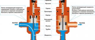
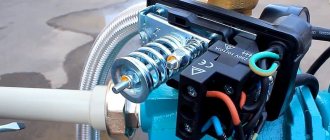
The device consists of the following parts:
- A pipe through which liquid enters the device;
- A membrane that plays the role of one of the walls of the internal chamber of the device;
- Reed switch, which is responsible for opening and closing the circuit in the electrical circuit of the pump;
- Two springs of different diameters - by compressing them, the water pressure is controlled, at which the liquid flow sensor will be triggered.
The principle of operation of the relay is as follows:
- When water enters the inner chamber of the device, it puts pressure on the membrane, thereby moving it to the side;
- The magnet located on the reverse side of the membrane becomes closer to the reed switch, which causes its contacts to close and the pump to turn on;
- If the water level drops, the membrane with the magnet moves away from the switch, which opens its contacts and turns off the pump.
Installing a liquid flow indicator into a pipeline is quite simple. To do this, you need to study the features of connecting the device and its correct configuration.
Sensor types
Today, the most popular and advanced water flow devices are reed switch relays and Hall sensors.
Description:
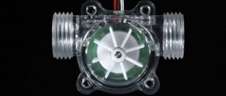
- A flow meter or Hall sensor is a small turbine with a magnet. As soon as the turbine begins to rotate, the magnet creates a field and generates electrical pulses that are transmitted to the boiler board (for example, Ferroli).
- The reed switch regulator also uses magnetism. A float magnet is installed inside the chamber. As soon as the water pressure increases, the float moves and begins to act on the reed switch (several magnetic plates that move apart under the influence of the float).
Installation
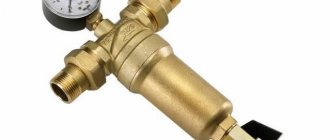
Considering that most water flow sensors are structurally included in the devices, their installation is required only in case of replacement due to failure. However, there are situations when the water flow sensor must be installed separately, for example, when there is a need to increase the water supply pressure.
After all, situations often occur when there is insufficient pressure in the central water supply system, and in order to turn on the gas boiler in hot water supply mode, it is necessary to create good pressure. In this case, an additional circulation pump is installed, equipped with a water flow sensor.
In this case, the sensor is installed after the pump, so when the water starts moving, the sensor turns on the pump and the water pressure increases.
Flow sensor malfunctions
Common malfunctions that may occur during operation:
- The DHW mode does not start, the equipment is unstable. To make sure that it is the regulator that has failed, you need to take a multimeter and measure the resistance. If it is approximately 2.5 kOhm, then according to the table this indicator should be achieved when heated to 60 degrees. But if the device is cold, then the problem is definitely in the water flow sensor. The regulator will “say” that the water is already heated and additional temperature is not needed. To fix the problem, you will have to completely replace the failed sensor. But we must not forget that it has direct contact with water and before removal it is necessary to drain all the water from the boiler (Baksi or other companies) and shut off its supply.
- If error No. 201 appears on the indicator, this means that there is a break or damage to the wires that are connected to the regulator. For the regulator to work normally, you need to restore its original position.
- Error No. 202 - short circuit. In this case, you need to check the device itself or the wires that are connected to it.
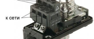
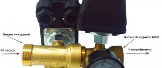
Flow switch connection diagram
The following figure shows a typical diagram for connecting a flow sensor for a pump.
If there is no flow, NO contact 1-2 is open, and NC contact 1-3 is closed, the power circuit is open, and the pump is stopped. When a flow of water appears through the relay, its contacts change their state, the power supply circuit of the pump is closed and it turns on.
Tags: Automation of gas boilers, hot water supply, flow sensor, relay, flow switch, relay logic, pump control
Top 3 best sensors
Based on user reviews, there are three best devices that you should pay attention to when purchasing:
- Regulator for the Grundfos UPA 120 pump. The equipment turns on automatically, but can be started as needed. Used in a private house or apartment where an independent water supply system is installed. The sensor will begin to function when the flow of incoming liquid is as stable as possible (range - 90-120 liters per hour). The purpose of the installation is to avoid idling of the heat generator installed in the house.
- Genyo – Lowara Genyo 8A. The water supply system is controlled based on the actual fluid flow. Automatically monitors pressure during operation.
- Sensor 1.028570. Can work with Immergas double-circuit boilers. Compatible with models: Mini 24 3 E, Victrix 26, Major Eolo 24 4E | 28 4E. The Hall sensor will ensure a stable outlet water temperature.
Fitting devices
The most common devices for pumps are fitting modifications, which are produced with a single chamber. Their plates are usually located in a horizontal position. Some modifications are equipped with two valves. And their maximum pressure parameter is approximately 5 Pa. Protection systems of the P58 class are quite often used. In this case, the conductivity depends on the size of the fitting. Some modifications can boast high pumping speeds. Their connections are quite often of the threaded type. There are also clip-on sensors on the market, which are not very popular.
Devices for circulation pumps
Sensors for circulation pumps are in great demand. A distinctive feature of the modifications is considered to be low reducibility. The maximum pressure is on average 3.3 Pa. Protection systems are used in a variety of classes. Devices with two cameras are very rare. When choosing a model, it is important to pay attention to the shape of the fitting. It should have a wide head and a narrow channel. Otherwise, leaks will occur frequently. Additionally, it is worth noting that float-based devices are available on the market. Their contacts are designed for adapters.
Devices with three cameras
Sensors for three chambers are connected for centrifugal pumps. Their ultimate compressive force is very high. It is also worth noting that models are produced with short channels. Their valves are of the rotary type. They are protected by a special membrane. According to experts, conductivity depends on the size of the chamber. If we talk about designs, it is worth noting that there are models on the market with elongated fittings. They have extremely low suction power. However, they can last a long time. Devices with switches are very rarely found in stores. As a rule, three-chamber models are produced with small taps.
Functional purpose of the flow switch
In household water supply systems, the action of a pumping station without water quite often occurs and threatens an accident. This problem is called “dry running”.
As a rule, the liquid cools and lubricates the elements of the system, thereby ensuring its normal operation. Even short-term dry operation leads to deformation of individual parts, overheating and failure of the equipment motor. Negative consequences apply to both surface and deep-well pump models.
Dry running occurs for various reasons:
An automatic sensor is necessary in order to completely protect the device from the threats posed by a lack of water. It measures, controls and maintains constant water flow parameters.
The main purpose of the relay is to independently turn off the pumping station when the liquid flow is insufficient and turn it on after normalization of the indicators.
Features of models with two cameras
Sensors for two chambers, as a rule, are distinguished by their large dimensions and high pressure parameter. There are many two-valve models on the market. They have a suction force of 4 N. Protection systems are used in the P88 series. The sensor plates are always installed in a horizontal position. If we talk about the disadvantages of devices, it is important to note that they use very large output channels. The models are not uniquely suitable for pumps with a power of up to 8 kW. There are devices on the market with and without taps. Additionally, there are modifications based on contactor switches.
Operating principle of sensors
Thermostats, as well as programmers, essentially work on the same principle. You set the temperature threshold when it falls below which the boiler heating is turned on. The difference between the devices is only in their response threshold, which directly depends on the quality. Chinese analogues of well-known devices, as a rule, have a longer response threshold than the European original.
The normal threshold is considered to be one degree. For example, if you set the temperature to maintain at 20 degrees, then at the normal threshold, when the temperature drops below 19, the boiler will start working. And when it rises above 21, it will turn off.
Chinese analogues have expansions of up to two degrees or more, which accordingly affects the quality of the burner. At the same time, more expensive and high-quality models from European manufacturers may have an error of only 0.2 degrees for example.
Types of sensors
By connection type, meters are divided into:
Loading …
- wired - connected to the boiler by wire, and monitoring it at a relatively short distance from the boiler (depending on the length of the wire);
- wireless - their operation is regulated using a radio signal. Wireless ones consist of two blocks, one of which is installed near the boiler, switching its operating modes and at the same time serving as a signal receiver from the second block. The second block can be placed in any convenient place and can be transported. Good radio signal quality depends on the number and quality of walls running between the two units, and it is generally not recommended to exceed the distance between them by more than 35 meters.
Wireless temperature sensor
By functionality they are divided into:
- Simple.
They maintain a strictly set temperature in the room under their control.
- Programmable - they are also programmers.
Allows you to configure temperature conditions (intervals for warming up the room, and the temperature to which it needs to be heated at different times). This allows you to set the boiler operating program for each day of the week.
- With hydrostat.
They have a built-in hydrostat that monitors the humidity in the room and allows you to regulate the microclimate by increasing or decreasing the humidity if necessary.
Main types of sensors
The main principle of operation of all sensors is signal conversion and interpretation of the result to promptly inform the user about changes in the operation of the gas boiler.
Gas equipment is equipped with a set of additional equipment, thanks to which it can be programmed for operation in a certain mode.
A compact overheat sensor extends the life of the gas boiler and prevents it from deteriorating due to high water temperatures
Key sensors responsible for equipment safety:
- traction;
- temperatures (outdoor and room);
- flame;
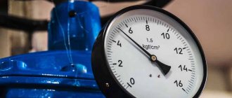
- pressure sensors (pressostat);
- overheating
Let's consider the characteristics and operating features of each of them.
To determine the draft force, the device uses a draft sensor or a thermal relay for a gas boiler, which is also responsible for the correct combustion of gas.
Thanks to this small draft sensor, carbon monoxide will not enter the room, but will be discharged through the chimney to the street
- Gas fire extinguishing
Draft is necessary to rid the boiler of carbon monoxide. Normal draft “removes” combustion products from the room, and not into it; weak draft can provoke attenuation of the column and, as a result, an accident.
Most often, such sensors are installed in a smoke extractor. If the sensor breaks down, smoke from combustion products enters the room and poses a threat to life safety.
The type of sensor depends on the type of boiler you want to connect it to. The first type is boilers with natural draft, the second - with forced draft.
The diagram clearly shows the difference in the operation of open and closed combustion chambers in gas boilers, as well as in the chimney structure
In devices with natural draft, the combustion chamber is open. During normal operation, carbon monoxide escapes through the chimney, and a safety thermostat monitors the presence of draft and the temperature of the flue gases. In such boilers, a sensor is used in the form of a metal plate with a contact attached to it.
The principle of its operation is to send a signal to the valve, which at the right moment will shut off the gas flow to the burner. Inside the thermostat there is a metal strip that reacts to changes in temperature.
The thermostat is adjusted to a certain temperature in accordance with the fuel in the boiler. If natural gas is used, then the temperature limits will be from +75 °C to +950 °C, in the case of liquefied gas - +75-+1500 °C.
If there is a malfunction in the process of carbon monoxide escaping (through the chimney to the street), in other words, the traction force is disrupted, then the device is triggered. When this happens, the temperature inside the apparatus rises, the metal expands, the sensor is triggered and the boiler cools down.
Owners of gas appliances with natural draft should pay attention to the concept of “reverse draft”. In simple words, this is a process in which carbon monoxide enters the room rather than being discharged into the chimney.
Failure occurs when temperatures fluctuate, incorrect installation of the chimney or its clogging, and inaccurate calculations of the dimensions of the chimney can also affect it. Regardless of the cause of backdraft, it must be eliminated immediately in order to avoid carbon monoxide poisoning.
Strong backdraft in action. It can provoke poisoning of residents of an apartment or house due to the large amount of carbon monoxide in the room
In devices with forced draft, a closed combustion chamber is installed and the gas is removed by a turbine-fan. A pneumatic relay sensor made in the form of a membrane is used here.
With normal draft, the membrane is slightly deformed under the force of carbon monoxide. When the flow becomes too weak and the membrane remains motionless, the contacts are disconnected and the gas valve closes. Such a sensor controls both the operation of the fan and the speed of combustion products.
If there is any doubt about the operation of the device that interrupts the gas supply in the event of a leak, it is advisable to install a carbon monoxide detector near the gas equipment. Its installation is strongly recommended, but not required.
Reasons for the draft sensor to be triggered: errors in the installation of the boiler or chimney, clogged chimney or fan stoppage (only in devices with forced draft).
The operating principle and design of the gas boiler automation system are described in detail in the following article, which we recommend that you read.
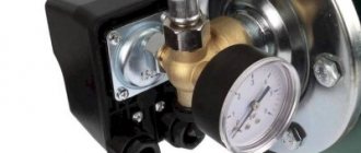
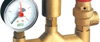
Operating principle of the pressure switch
A pressure switch or pressure sensor protects the boiler from overheating during a sudden change in gas pressure or a decrease in water flow.
Installing a pressure switch protects gas equipment from sudden or too large pressure surges and, if necessary, turns off the gas equipment
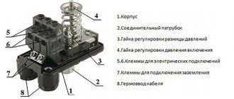
Visually, this is a standard electrical sensor or relay, in most cases with two electrical corrector circuits. It is these circuits that determine the two key operating modes of the device:
- Mode 1 assumes normal pressure, during which the thermostatic membrane of the sensor does not change location and the first group of contacts closes. The boiler operates normally due to the passage of current through this circuit. It is also always connected to the general circuit of the unit.
- Mode 2 The mode is activated when some system parameter is out of normal range. Inside the relay, the thermostatic membrane shifts and bends. The first circuit of the controller is disconnected thanks to the membrane, and the second is closed. Boiler equipment stops working correctly. The operation of the standby mode, informing the boiler user about an emergency, is activated using the secondary circuit of the sensor.
The sensor is triggered even if there is the slightest increase in temperature in the combustion chamber. It monitors the minimum/maximum value of the pressure force, and also registers the beginning of moisture condensation in the combustion products or directly in the gas itself.
What does the overheat sensor monitor?
An overheating sensor is a small device that protects a gas boiler from boiling, which can occur when the temperature rises above +100 °C. When the limit temperature in the heating circuit is reached, the overheating sensor disconnects the contacts and turns off the gas appliance.
A special NTC (abbreviation for positive temperature coefficient) sensor is an immersion device. which controls the temperature inside the gas boiler
The device is based on either thermistors or biometric plates, sometimes these can be working NTC sensors.
Causes of gas boiler overheating and options for eliminating them:
- Lack of circulation in the heating circuit due to clogged filters. It is necessary to carefully clean all filters, rinse them or, if necessary, replace them with new ones.
- “Airing” of the heating circuit. You can get rid of it by simply removing the air.
- The duct is clogged due to a large layer of scale, and the boiler can be heard as if it is “knocking” or making popping noises. Remove excess in the device using special chemicals or acids.
- When starting the boiler, noise sounds are heard and the device may display an “insufficient circulation” error. A similar situation is possible when starting up the boiler, after its long-term downtime and without first running the ventilation system. The cause may be clogging in the pump due to inactivity. You need to disassemble the pump and wash it thoroughly, and then start it again.
- The equipment installation location was chosen incorrectly. In this case, if the air humidity or low temperature in the room is high, the metal from which the boiler is made will begin to quickly deteriorate.
For any reason of overheating, it must be removed immediately to avoid boiler breakdown or explosion. The user can get rid of overheating either independently or using the services of an experienced technician.
Outdoor and room temperature sensors
The main task of a temperature sensor for a gas boiler is to control the temperature and timely inform about its changes. Modern response devices operate on the principle of electrical resistance, which allows recording of operating readings.
According to the method of transmitting information, temperature sensors are:
- wired (connected to the controller using a cable);
- wireless (wireless radio communication is used to transmit the signal; such models consist of 2 parts).
Based on the type of control, they are divided into simple (maintain the temperature in the room) and programmable (there are many functions that allow you to influence the thermal conditions in the house).
A complex programmable temperature sensor can be conveniently placed in a room and, using several buttons, regulate the temperature
Some sensor models have a built-in thermostat that allows you to control the humidity level in the room. There is also a function to reduce/increase humidity.
Depending on the placement method, the following devices are distinguished:
- overhead – attached to the heating circuit pipes;
- immersed - are in constant contact with the coolant.
In this case, indoor ones are located directly in the room, and outdoor ones are installed outside and react to temperature changes outside the window.
The first two types are used for coolant, i.e. for the boiler, and the second two are for controlling the air temperature. Overlays are mounted on the outer surface of the pipeline using a special tape or clamp.
Using a simple clip-on temperature sensor, the user can easily set comfortable temperature indicators, which the boiler will maintain
Submersible water heating sensors for the boiler are placed only in special places inside the device in close proximity to the coolant.
The response element for measuring temperature degrees can be an electrical transducer (thermocouple, resistance thermometer), pre-configured to a certain range. Such devices may have a display; some models have the ability to be calibrated in advance.
An outdoor temperature sensor allows the boiler to operate not all the time, but only when necessary. This increases the life of the gas boiler and the consumption of gas itself. When installing it, protection from mechanical and weather (moisture, frost) influences should be provided in advance.
The set of remote equipment includes:
- the sensor itself;
- terminals for clamping electrical cables;
- cable sleeve;
- a plastic case that will contain all the parts of the device.
When the temperature outside the window changes, the gas boiler sensor triggers a weather-dependent program that makes changes to the temperature regime for heating water for heating.
An outdoor temperature sensor is mounted on the outer wall of the room. When choosing it, you should check the device’s protective mechanisms in advance
The room sensor reacts to changes in temperature in the room, then sends information to the automation system, which controls the boiler. And it already gives a signal to reduce or increase the heating power of the heating circuit.
The principle of operation is that the user must initially set the required temperature in the room, and the equipment itself will control the gas equipment.
The boiler will be turned on only if the air temperature in the heated room is lower than the previously set one. This way, you will reduce your monthly gas bill by about a third.
A room temperature sensor will allow you to set the boundaries of a comfortable temperature regime, and then the equipment will maintain it in constant mode
When selecting a temperature sensor, pay special attention to the temperature range. The best option would be from – 10 °C to + 70 °C. Also consider the threshold temperature. There are models that respond to a decrease in temperature by 1/4 degree.
This is not very convenient, since the boiler will often turn off. However, most operate when the temperature changes by 0.5 or 1 degree.
The dimensions of the device itself are generally small: 2x3 cm. In wired models, the cable length must be at least 5 m. If wireless communication is used, be sure to test the radio signal.
The rules and nuances of adjusting the automation of gas heating equipment are described in detail in the article, the material of which is entirely devoted to this issue.
Flame sensor - reliable protection of your boiler
One of the key guarantees of safe operation for a gas boiler is the flame sensor. Its main task is to send a signal about the extinguishing of the flame on the burner to the automation system as quickly as possible to shut off the gas in order to prevent its leakage and explosion of the entire device. Also, this sensor should inform the controller about the quality of gas combustion, the presence of flame, and the intensity of combustion.
Types of flame sensors
They depend on the method of flame control when operating a gas boiler. Control can be direct or indirect. Thermometric, photoelectric, ultrasonic, ionization and are direct methods.
Indirect control is considered to be control over the formation of carbon monoxide in the firebox, over the fuel pressure in the pipeline through which it enters, over the pressure force or its fluctuations in front of the burner. This also includes checking for an inexhaustible source of ignition.
Based on the thermoelectric control method, the sensor includes a thermocouple (it includes a sensor and a solenoid valve). The thermocouple is placed in close proximity to the boiler burner, and the solenoid valve is mounted on the gas pipeline through which gas is supplied to the burner being ignited.
Connecting a flame sensor allows you to use a gas boiler or water heater at home without fear for your own life
Many modern devices install flame ionization sensors . Their operating principle is that when a flame burns, an ionization current occurs between the housing and the electrode of the sensor. It is formed in the event of attraction of ions. If there is no such current, then this becomes a signal to stop the gas supply.
If the combustion of the pilot flame produces the required amount of free electrons and negative ions, then the automation activates a key device that allows the operation of the main burner.
Please note that correct operation of the ionization sensor is only possible with an accurate phase connection of the heating boiler to the electrical network.
It is this mechanism that is much more effective than others in the case of gas combustion, since the gas does not actually produce light, so the photocell does not always react. The infrared radiation remains for a short time, which may be enough for a large amount of gas to accumulate, which automatically makes the infrared flame detector less safe.
The ionization sensor is mounted inside the boiler itself. It prevents accidents on gas equipment and protects the life and property of home or apartment owners
Photosensors monitor the flame of the key burner, but they are not used to diagnose the igniter flame due to the insufficient size of its flame. Such sensors are divided according to their response to the wavelength of the light flux: some respond to the visible and infrared spectrum of the light flux from a burning flame, while others “see” only its ultraviolet component.
To operate correctly, photocells must have “direct contact” with the burner flame, so they are mounted in close proximity to it. They are installed on the burner side at an angle to its axis of 20-30°. Because of this, photo sensors are susceptible to overheating by thermal radiation from the walls of the unit and heating through the viewing window.
In order to protect the photosensor from overheating, heat-resistant quartz glass and forced airflow are used, which is carried out either by low-pressure compressed air or by air produced by a fan.
The flame sensor may be triggered. when the key gas-air ratio is disrupted or the ignition device or valve becomes dirty. If the flame sensor breaks for any reason, it should be replaced immediately. This will save the life and health of you and your family.
Equipping gas heating equipment with a full set of safety sensors and automation devices does not eliminate the need for regular maintenance. How technical inspections and repairs of gas units are carried out is described in detail in the article we recommend.
Design and operating principle
The sensor has a unique device, thanks to which it performs its direct functions. The most common modification is the paddle relay.
The classic building scheme includes the following important elements:
While the chamber is filled with liquid, the force of the flow begins to act on the valve, moving it around its axis.
A magnet built into the back of the petal comes close to the reed switch. As a result, the contacts close, turning on the pump.
When the flow of fluid stops and the pressure in the system drops below normal, the compression of the spring weakens, returning the valve to its original position. Moving away, the magnetic element ceases to operate, the contacts open and the pumping station stops.
Some modifications are equipped with a return magnet instead of springs. Judging by user reviews, they are less susceptible to minor pressure surges in the system.
Depending on the design solution, several more types of relays are distinguished. These include rotary devices equipped with a paddle wheel rotating in a water flow. The speed of rotation of the blade in them is controlled by touch sensors. If there is liquid in the pipe, the mechanism deflects, closing the contacts.
There is also a thermal relay that operates according to thermodynamic principles. The device compares the temperature set on the sensors with the temperature of the working medium in the system.
If there is flow, a thermal change is detected, after which the electrical contacts are connected to the pump. If there is no water movement, the microswitch disconnects the contacts. Thermal relay models are characterized by high sensitivity, but they are quite expensive.