How to adjust the pressure on a compressor
A compressor is a device for compressing air masses, from which it is subsequently possible to extract the energy necessary for a huge number of different tools. Today we will look at such an important component as compressor pressure.
If the pressure is incorrectly set, even the best equipment will not function properly. In case of a breakdown or malfunction of the compressor, Megatechnika service specialists will help you.
It is important to know some rules for working with these devices.
Adjusting the compressor outlet pressure
A compressor is a device for compressing air masses, from which it is subsequently possible to extract the energy necessary for a huge number of different tools.
Today we will look at such an important component as compressor pressure. If the pressure is incorrectly set, even the best equipment will not function properly. In case of a breakdown or malfunction of the compressor, Megatechnika service specialists will help you.
It is important to know some rules for working with these devices.
First option
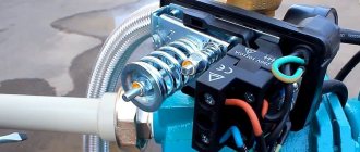
The operation scheme of all compressors is the same. After the required amount of air has been collected, the automatic control element weakens and stops air intake. An air pressure controlled relay works on the principle of pressing air onto a membrane and counteracting an elastic spring.
To manually adjust the compressor pressure, there is a switch in the form of a bolt or nuts that allows you to adjust the pressure of the unit. To access it you need to do the following:
- remove the protection in the form of a casing;
- the compressor pressure is adjusted by rotating either a bolt or two nuts, which increase or decrease the spring pressure force;
- There is a nut nearby for adjusting the differential pressure on and off;
- turn the pressure adjustment bolt to change the indicators, determine the desired indicator experimentally.
Complete set of automatic units and safety issues
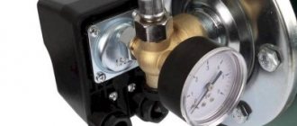
Structurally, the pressure switch for a compressor has the form of a compact block with inlet pipes, a membrane, and sensing spring elements. There are also mandatory subassemblies - switch (mechanics), unloading valve. The pressure switch assembly, which operates on perception, contains a spring block; a screw is used to compress it. Factory settings are pressure in the range of 4–6 atmospheres. Relevant information is provided in the instruction manual.
Budget differential air pressure switches are rarely equipped with automatic equipment; premium solutions have it. Installation location: receiver. For long-term operation, a pressure switch is needed; it will prevent overheating of the working units. The rigidity, flexibility, and elasticity of spring elements depend on the temperature parameters of the environment. Industrial devices are designed in such a way that they provide stable and stable operating values in the temperature range -5–+80 ºC.
The membrane is connected to the switch. When moving, it will adjust the operation of the pressure switch.
Why do you need an unload valve?
The unloading unit is connected to the air supply line. This allows excess pressure to be released from the piston compartments. At the same time, the retractable compressor units are relieved from the application of excessive force.
The unloading element is located between the check ejector valve and the compression block. When the drive stops, the unloading section will be activated. Excess pressure is released through it from the piston compartment. Further, during the start, acceleration of the electric motor, an onslaught will be created that blocks the valve mechanism. This prevents drive overload and facilitates the process of starting the device in off mode.
The unloading system may contain time intervals of switching on. The mechanism will open after the engine starts. The main ranges are sufficient for maximum engine torque. The mechanical switch is responsible for starting and stopping the execution of basic functions. There are two positions - on and off. The on mode activates the drive mechanism, the compressor begins to operate according to a pre-programmed pattern. The second program prevents unauthorized switching on at low pressure settings.
Safety valve
Shut-off valves prevent emergency situations in the event of breakdown of the elements included in the control circuit. We are talking about a motor, a piston unit. The safety of industrial installations must be sufficient. To do this, the regulator is equipped with a safety valve, which guarantees the protection of system operation even if the relay does not operate correctly.
Shut-off valves prevent emergency situations in the event of breakdown of control system elements. The safety of industrial structures must be at a very high level. To increase it, the compressor regulator is equipped with a safety valve.
The second way to regulate pressure
Another method, which is sometimes much more convenient and practical than the first, is adjustment through a gearbox. A reducer is a device that takes in air already in a compressed state. This air must be transferred to the final apparatus.
These devices, gearboxes, also have a control element in the form of a valve. The pressure control range can be controlled, and the indicators depend on the power and capabilities of the compressors that are connected to the gearbox.
There are special models with the function of conveniently adjusting the supplied air pressure for each specific working tool. Sometimes such devices even have an option that relieves excess pressure, eliminating the excess and maintaining the safe, uninterrupted operation of any connected tool.
Essential Security
Tips in the article “Why do you need a screw compressor” here.
This ability to regulate pressure is present on all units that use compressed air energy for production. Plus, the gearboxes of such machines provide pressure control at all stages in order to ensure the safe operation of all parts of the working structure.
Source
Design and principle of operation of the automation unit
To maintain the pressure in the receiver at a certain level, most air compressors have an automation unit, a pressure switch.
This piece of equipment turns the engine on and off at the right time, preventing the compression level in the storage tank from being exceeded or too low.
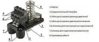
The pressure switch for the compressor is a unit containing the following elements.
- Terminals. Designed for connecting electrical cables to relays.
- Springs. Installed on adjusting screws. The pressure level in the receiver depends on the force of their compression.
- Membrane. It is installed under the spring and compresses it under the action of compressed air.
- Power button. Designed to start and force stop the unit.
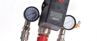
- Connection flanges. Their number can be from 1 to 3. The flanges are designed for connecting the compressor start relay to the receiver, as well as for connecting a safety valve with a pressure gauge to them.
In addition, automation for the compressor may have additions.
- Unloading valve. Designed to relieve pressure after a forced stop of the engine, which makes it easier to restart.
- Thermal relay. This sensor protects the motor windings from overheating by limiting the current.
- Time relay. Installed on compressors with a three-phase motor. The relay turns off the starting capacitor a few seconds after the engine starts.
- Safety valve. If the relay malfunctions and the compression level in the receiver rises to critical values, then in order to avoid an accident, the safety valve will operate, releasing the air.
- Gearbox. Pressure gauges are installed on this element to measure air pressure. The reducer allows you to set the required level of compression of the air entering the hose.
The operating principle of the pressure switch is as follows. After the compressor engine starts, the pressure in the receiver begins to increase. Since the air pressure regulator is connected to the receiver, the compressed air from it enters the membrane relay unit. The membrane bends upward under the influence of air and compresses the spring. The spring, compressing, activates the switch, which opens the contacts, after which the engine of the unit stops. When the compression level in the receiver decreases, the membrane installed in the pressure regulator bends down. At the same time, the spring opens, and the switch closes the contacts, after which the engine starts.
Compressor - device and principle of operation
The name of the device in question comes from “compressio”, which is translated from Latin as “compression”. The main purpose is to compress a gaseous substance in order to move it and use pressure force .
Pressure compressors produced by modern industry are divided into several types and subtypes. Based on the method of gas compression, two large groups of devices are distinguished: volumetric and dynamic. The pressure in them is created by different methods, and accordingly the principle of operation is different.
The design of volumetric models consists of working chambers with a system of valves in which the process of compression and movement of gas is carried out. Schematically, the principle of operation looks like this: the working substance enters the chamber through the inlet valve, which opens only inward and prevents gas from escaping outward. The gas is then compressed by reducing the volume of the chamber and pushed to the outlet valve, which also opens in one direction - outward.
Dynamic designs compress gas by accelerating its movement using a screw system. As a result, the energy of motion is converted into compression force.
On a note! In addition to the principle of operation, compressor devices are divided into groups according to the type of working substance (air, steam, any gas or a mixture of them), the type of drive, the method of heat removal, the industry used, and the final pressure.
Diagrams for connecting the pressure switch to the compressor
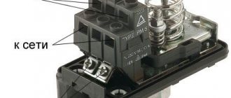
The connection of the relay that controls the degree of air compression can be divided into 2 parts: the electrical connection of the relay to the unit and the connection of the relay to the compressor through the connecting flanges. Depending on which motor is installed in the compressor, 220 V or 380 V, there are different connection diagrams for the pressure switch. I am guided by these diagrams, provided that you have certain knowledge in electrical engineering, you can connect this relay with your own hands.
Connecting the relay to a 380 V network
To connect the automation to a compressor operating from a 380 V network, use a magnetic starter. Below is a diagram of connecting automation to three phases.
In the diagram, the circuit breaker is indicated by the letters “AB”, and the magnetic starter by “KM”. From this diagram it can be understood that the relay is set to a switch-on pressure of 3 atm. and shutdown - 10 atm.
Connecting the pressure switch to a 220 V network
The relay is connected to a single-phase network according to the diagrams given below.
These diagrams indicate various models of pressure switches of the RDK series, which can be connected in this way to the electrical part of the compressor.
Connecting the pressure switch to the unit
Connecting a pressure switch to a compressor is quite simple.
- Screw the pressure switch onto the receiver pipe using its central threaded hole. For better thread sealing, it is recommended to use fum tape or liquid sealant. The relay can also be connected to the receiver through a reducer.
- Connect a relief valve to the smallest output from the relay, if present.
- The remaining outputs from the relay can be connected to either a pressure gauge or a safety relief valve. The latter is installed without fail. If a pressure gauge is not required, then the free output of the pressure switch must be plugged with a metal plug.
- Next, wires from the electrical network and from the engine are connected to the sensor contacts.
After the complete connection of the pressure switch is completed, it is necessary to configure it for proper operation.
Connection diagram
Pressure switches for compressors can be for different load connection schemes. For a single-phase engine, a 220-volt relay is used, with two groups of connections. If we have three phases, then install a 380-volt device that has three electronic contacts for all three phases. For a three-phase motor, you should not use a relay for a 220-volt compressor, because one phase cannot be switched off from the load.
Flanges
The device may include additional connection flanges. Usually equipped with no more than three flanges, with a hole size of 1/4 inch. Thanks to this, you can connect additional parts to the compressor, for example, a pressure gauge or a safety valve.
Connecting a pressure switch
Relay installation
Let us turn to the issue of connecting and adjusting the relay. How to connect a relay:
- We connect the device to the receiver via the main output.
- If necessary, connect a pressure gauge if there are flanges.
- If necessary, we also connect a relief and safety valve to the flanges.
- Channels that are not used must be closed with plugs.
- Connect the electric motor control circuit to the pressure switch contacts.
- The current consumed by the motor should not be higher than the voltage of the pressure switch contacts. Motors with low power can be installed directly, and with high power, the required magnetic starter is installed.
- Adjust the parameters of the highest and lowest pressure in the system using the adjusting screws.
The compressor relay should be adjusted under pressure, but with the engine power supply turned off.
When replacing or connecting a relay, you should know the exact voltage in the network: 220 or 380 volts
Relay adjustment
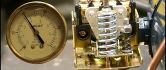
The pressure switch is usually sold already configured and adjusted by the manufacturer, and does not require additional adjustments. But sometimes it becomes necessary to change the factory settings. First you need to know the compressor parameter range. Using a pressure gauge, the pressure at which the relay turns the motor on or off is determined.
After determining the required values, the compressor is disconnected from the network. Then remove the relay cover. Underneath there are two bolts of slightly different sizes. Using the larger bolt, the maximum pressure is adjusted when the engine should be turned off. It is usually denoted by the letter P and an arrow with a plus or minus. To increase the value of this parameter, turn the screw towards “plus”, and to decrease – towards “minus”.
The smaller screw sets the difference between the on and off pressures. Indicated by the symbol “ΔΡ” and an arrow. Usually the difference is set at 1.5-2 bar. The higher this indicator, the less often the relay turns on the engine, but at the same time the pressure drop in the system will increase.
Adjusting the compressor pressure
As mentioned above, after creating a certain level of air compression in the receiver, the pressure switch turns off the unit’s engine. Conversely, when the pressure drops to the switching limit, the relay starts the engine again.
Important! By default, relays, both single-phase devices and units operating from a 380 V network, already have factory settings. The difference between the lower and upper engine start threshold does not exceed 2 bar. It is not recommended for the user to change this value.
But often situations that arise force you to change the factory settings of the pressure switch and adjust the pressure in the compressor at your discretion. You can only change the lower switching threshold, since after changing the upper switching threshold upward, the air will be released by the safety valve.
Pressure adjustment in the compressor is carried out as follows.
- Turn on the unit and record the pressure gauge readings at which the engine turns on and off.
- Be sure to disconnect the device from the power supply and remove the cover from the pressure switch.
- After removing the cover, you will see 2 bolts with springs. The large bolt is often designated by the letter “P” with the signs “-” and “+” and is responsible for the upper pressure, upon reaching which the device will be turned off. To increase the level of air compression, turn the regulator towards the “+” sign, and to decrease it, turn towards the “-” sign. First, it is recommended to make half a turn with the screw in the desired direction, then turn on the compressor and check the degree of pressure increase or decrease using a pressure gauge. Record at what indicators of the device the engine will turn off.
- Using a small screw you can adjust the difference between the on and off thresholds. As mentioned above, it is not recommended that this interval exceed 2 bars. The longer the interval, the less often the device’s engine will start. In addition, the pressure drop in the system will be significant. Setting the on-off threshold difference is done in the same way as setting the upper on-off threshold.
In addition, you need to configure the gearbox if it is installed in the system. It is necessary to set the compression level on the gearbox to a level that corresponds to the operating pressure of the pneumatic tool or equipment connected to the system.
How to set the compressor to the desired pressure?
Compressors are supplied with factory settings for switching on and off. As a rule, buyers decide to change standard settings for two reasons.
First: such changes are dictated by the technical characteristics of the connected instrument.
Second: the desire to save energy and reduce the load on the pneumatic system.
For example, a pneumatic tool is connected to the system, whose maximum pressure threshold is lower than that set on the injection unit. If you do not reduce the compression level, the tool will fail. You can use a pressure reducing valve to adjust the degree of compression of the air supplied to the pneumatic system, but this will be a half-measure. Why force the compressor unit to work with force, pumping more than necessary?
Another case: the relay is activated at a minimum compression of 8 atmospheres, and a value of 6 bar is sufficient for the connected pneumatic tool to operate. By setting the compressor to a lower pressure, you can save up to 10% in energy. The load on the pneumatic system: pipes, hoses, fittings, fittings is reduced.
To set the compressor to the desired pressure, you need to change the pressure switch settings. You should interfere with the functionality of this device only if there are no other solutions to the problem. It is better to entrust this work to a specialist.
How to set the compressor pressure switch?
This operation must be performed with the receiver full but the power turned off. You should turn on the compressor, wait until the pressure switch operates and the engine stops. The actual readings of maximum compression are recorded on the pressure gauge. Then you should cut off the electricity supply.
It is strictly forbidden to manipulate the pressure switch if the compressor is not disconnected from the power supply!
You need to remove the pressure switch cover. It is located on the receiver or supply line, usually with a red or white “compressor start” button. Black plastic box. Under the cover there are two screws (sometimes nuts). The larger screw (marked P) adjusts the maximum pressure at which the engine turns off. By rotating the screw towards the “+” or “-” signs, set the required value. If the compression ratio is set too high, the relief valve will trip.
Pressure regulation of a piston compressor
During operation of the compressor, it may be necessary to adjust the pressure according to the specified parameters or shift the on/off threshold at the lower and upper pressure. In this article we will take a detailed look at how you can do this yourself, without contacting customer service.
So, before we give specific recommendations, let's remember some of the operating features of piston compressors. One of them is that piston compressors have an intermittent operating mode, that is, they cannot operate continuously. In the passport for piston compressors you can read that a piston compressor can operate continuously for no more than 15-20 minutes per hour. However, if the compressor is selected correctly, then on average in 3-5 minutes the piston unit manages to force air into the receiver, only to then be forced to shut down. Otherwise, the piston block may overheat due to high temperatures. Therefore, having collected the required amount of compressed air into the receiver, the compressor turns off. This shutdown is carried out automatically - the so-called pressure switch. The task of the pressure switch is to open the electrical circuit that powers the engine. After this, the engine stops rotating and therefore does not drive the compressor pistons. Then, when the pressure in the receiver drops to a minimum level, the automation restarts the engine and the compressor begins to pump air again. The second feature of the operation of a piston compressor is that the difference between the minimum and maximum pressure, that is, between the lower and upper threshold, is 2 bar. This difference, as a rule, is already set by the manufacturer and should not be adjusted by the user.
But sometimes there are situations when it is still necessary to change the working pressure. Then you can call a specialist, or try to do it yourself.
However, you need to remember that you can adjust the pressure to the required value (highest and lowest) only in the lower direction. If you increase the pressure beyond the permissible limit, the safety valve will operate.
The principle of operation of a pressure switch (pressure switch) is to compare two forces, on the one hand there is an elastic spring, on the other there is gas pressure on the membrane.
Now let’s look in detail at how to adjust the working pressure on the pressure switch. To begin, record the on/off values on the compressor pressure gauge, that is, the upper and lower thresholds. Then, disconnect the compressor from the mains and remove the top plastic cover from the pressure switch.
Under it, you will see regulators in the form of two threaded bolts, one large, the other small. The large bolt regulates the compressor's upper cut-out pressure and is usually identified by the letter "P" and an arrow with "+" and "-" signs. It is necessary to turn the bolt in the desired direction: if upward, then towards “+”, if downward, then back. Next, we follow the experimental path, making half a turn and turning on the compressor using a pressure gauge and checking the upper shutdown threshold.
With a small bolt you can adjust the difference between the on and off pressure, it is indicated by “ΔP” and the corresponding arrow. Let us remind you once again that the difference between the minimum and maximum pressure, that is, between the lower and upper threshold, is 2 bar. It must be remembered that the greater this difference, the less often the compressor will turn on and the higher the pressure drop in the system. The adjustment process is similar to adjusting the upper pressure.
Another, less complicated way to regulate compressor pressure is to use a pressure regulator, or also called a pressure reducing valve.
The principle of operation of the pressure regulator is quite simple: it is necessary to set, using the pressure gauge with which it is equipped, the pressure that is necessary to carry out the work operation. There are different types of regulators, some come with filters, others have the additional function of relieving excess pressure. Depending on the compressor and the application, you determine the required equipment yourself.
Thus, all the rules described above for adjusting pressure on piston compressors will help you independently, experimentally, adjust the desired pressure without contacting a service center.
Source
Compressor operating pressure
The operating pressure of the compressor
is one of the main characteristics that must be taken into account when choosing a unit. The force with which the compressor compresses the gas depends on this parameter.
We all remember from school physics that gas, after compression, tries to return to its previous state. This property is used to power all air tools.
In addition, compressed gas takes up less space, making it more convenient to store. In some cases, gas (for example, methane) changes its properties when compressed, so it can only be used in this form.
The higher the pressure, the more the gas tends to expand. Simply put, we get stronger air flow. Different tools have different operating pressure requirements. Both too little and too much air flow will cause the air tool to not operate properly. Moreover, the risk of equipment failure increases. Therefore, it is important to choose the right compressor with the appropriate operating pressure.
So, we see that the operating pressure of the compressor determines its scope of application .
Pressure in compressors is most often measured in Pascals (Pa), bars (bar) or atmospheres (atm).
These units of measurement are related as follows:
1 bar = 0.987 atm = 0.1 MPa
All compressors can be divided into several groups depending on their maximum operating pressure:
from 0.25 bar – low pressure compressor. Mainly used in production for transporting liquids and solids. Also used in ventilation and water treatment systems.
from 6 bar – standard compressor, suitable for most types of work with various tools. Widely used both in everyday life and in production.
from 100 bar – high pressure compressor. The most common use is to fill various gas cylinders: for diving, for paintball, etc.
Remember that operating pressure is always indicated at the compressor outlet. As you move in the pneumatic network, the pressure gradually drops. This is especially noticeable in a long pneumatic network with a large number of local resistances (valves, bends, etc.). In addition, there is always a risk of a small leak. As a result, compressed air of lower pressure will reach the consumer.
To compensate for the loss of air, a small supply of outlet pressure is required. However, it is difficult to correctly select the required reserve on the compressor itself, especially in the case of a long pneumatic network. It is much more convenient to release excess pressure in front of the consumer. For this, a pressure regulator is used, which operates automatically.
Also remember that each additional bar of pressure increases energy consumption by at least 7%.
For this reason, you should not increase the pressure more than necessary.
Comparative data on the consumption of pneumatic tools:
| Pneumatic tool | Pressure (Bar) | Air flow (l/min) |
| Spray gun | 3-6 | 150-400 |
| Grinder | 6-7 | 180-450 |
| Bit | 6.5 | 220-390 |
| Impact wrench | 6-7 | 400-450 |
| Angle wrench | 6-7 | 85-250 |
| nail gun | 6-7 | 100-350 |
| Rivet gun | 6-7 | 100-350 |
| Drill | 6 | 110-280 |
| Scissors | 6.2 | 200 |
| Blow gun | 4 | 150-250 |
| Sandblasting gun | 8 | 250 |
| Tire inflation gun | 3 | 50 |
Remez compressor units type SB4/S-50.LV30 and others are devices designed to compress the air medium needed as an energy source for many tools, as well as for other equipment. Modern compressors are capable of pre-cleaning the air from large particles, dust and excess humidity, after which they compress and then cool the environment. These processes are necessary so that the finished product can be used in any industry that has a need for pressurized air.
One of the most important indicators of a compressor installation is the operating pressure of the compressor. That is, the air pressure that the compressor creates in the receiver and constantly maintains it. For the SB4/S-50.LV30 compressor unit, the operating pressure is 1.0 MPa (10.0 kg/cm2). A feature of piston compressors is that they cannot be operated around the clock - the amount of short-term work can be from 4 to 10 hours per working day, depending on the class of the machine. This factor must be taken into account when choosing equipment. Also, do not forget that the maximum operating air pressure in the receiver must exceed the total demand for this air due to possible pressure losses along the pipeline lines delivering air to the point of consumption. The reason for this may be: the diameter of the pipeline - the smaller the diameter, the greater the risk of pressure drop, many obstacles in the path of air, such as frequent corners, turns, labyrinths of shut-off valves. The cause may also be contamination of the line and filter elements.
All compressors operate according to one general scheme. Having collected the required amount of air into the receiver, the automatically controlled compressor stops pumping. The electric motor does not receive power and stops rotating, thereby not driving the compressor pistons. As soon as the pressure in the receiver reaches the minimum set value, the compressor starts again and replenishes the air flow. Timely shutdown and startup of the compressor is controlled by a device called a pressure switch. It interrupts the electrical circuit that powers the engine. The pumping process to maximum lasts 6-10 minutes. The difference between the maximum and minimum pressure is usually already set by the manufacturer; as a rule, this difference is 2 bar. However, it is also possible to independently adjust the compressor pressure; in this case, both pressures are applied – the highest and the lowest, but only in a downward direction.
The principle of operation of a pressure switch (pressostat) is based on the resistance of two forces - gas pressure on the membrane and the elasticity of the spring. In order to adjust the working pressure, it is necessary to remove the pressure switch cover; under it there are regulators in the form of threaded bolts; nearby there are indicators for the direction of the side in which the regulators should be tightened, compressing or releasing the spring. There is also a similar bolt nearby - a regulator of the difference between the maximum and minimum pressure.
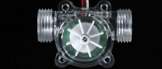
There is a valve at the inlet of the container; it prevents compressed air from escaping in the opposite direction when the compressor stops operating; it is called a check valve. Thanks to a 50-liter sealed container and a valve locking system, the air leaving the compressor eliminates pulsation and has a constant operating pressure at the outlet.
First option
The operation scheme of all compressors is the same. After the required amount of air has been collected, the automatic control element weakens and stops air intake. An air pressure controlled relay works on the principle of pressing air onto a membrane and counteracting an elastic spring.
To manually adjust the compressor pressure, there is a switch in the form of a bolt or nuts that allows you to adjust the pressure of the unit. To access it you need to do the following:
- remove the protection in the form of a casing;
- the compressor pressure is adjusted by rotating either a bolt or two nuts, which increase or decrease the spring pressure force;
- There is a nut nearby for adjusting the differential pressure on and off;
- turn the pressure adjustment bolt to change the indicators, determine the desired indicator experimentally.
The second way to regulate pressure
Another method, which is sometimes much more convenient and practical than the first, is adjustment through a gearbox. A reducer is a device that takes in air already in a compressed state. This air must be transferred to the final apparatus.
These devices, gearboxes, also have a control element in the form of a valve. The pressure control range can be controlled, and the indicators depend on the power and capabilities of the compressors that are connected to the gearbox.
There are special models with the function of conveniently adjusting the supplied air pressure for each specific working tool. Sometimes such devices even have an option that relieves excess pressure, eliminating the excess and maintaining the safe, uninterrupted operation of any connected tool.
Essential Security
Tips in the article “Why do you need a screw compressor” here.
This ability to regulate pressure is present on all units that use compressed air energy for production. Plus, the gearboxes of such machines provide pressure control at all stages in order to ensure the safe operation of all parts of the working structure.
Budget models of air compressors are not always equipped with a pressure switch, since similar devices are installed on the receiver. Therefore, manufacturers of this equipment believe that visual monitoring of the pressure developed by the compressor based on pressure gauge readings is quite sufficient. At the same time, during long-term work, in order to avoid engine overheating, it is advisable to install a pressure switch on the compressor. Then the drive will turn on and off automatically.
Design and diagram of a pressure switch for the compressor
All compressor pressure switches are divided into two types:
- Switching off the compressor electric motor when the air pressure in the network exceeds permissible limits (such designs are called normally open);
- Turning on the compressor electric motor when the pressure in the network decreases below permissible limits (such designs are called normally closed).
The actuator element of the pressure switch for the compressor is springs, the compression force of which is changed by a special screw. In the factory settings, the compression force of the springs is usually set to a pressure in the pneumatic network from 4 to 6 atm, as reported in the user manual. Since the rigidity and flexibility of spring elements depend on the ambient temperature, all designs of industrial pressure switches are designed for stable operation in the temperature range from -5 to +80ºС.
The design of the pressure switch includes two mandatory subassemblies - an unloading valve and a mechanical switch. The unloading valve is connected to the air supply line between the receiver and the compressor. It controls the operation of the electric motor. If the compressor drive is turned off, the unloading valve located on the receiver discharges excess compressed air (up to 2 atm) into the atmosphere, thereby unloading the moving parts of the compressor from the excess force that they will have to develop when the compressor is turned on again. This prevents critical overload of the engine in terms of permissible torque. When the unloaded engine starts, the valve closes and does not create unnecessary load on the drive.
A mechanical switch performs the stand by function, preventing accidental starting of the engine. After pressing the button, the drive turns on and the compressor operates in automatic mode. If the button is turned off, the compressor engine will not start even if the pressure in the pressure pneumatic network is lower than required.
In order to increase work safety, industrial designs of compressor pressure switches are also equipped with a safety valve. It is useful, for example, in case of sudden engine stop, piston failure or other emergency situation.
Optionally, a thermal relay can be installed in the pressure switch housing, with the help of which the current strength in the primary circuit is monitored. If for some reason this parameter increases, then, in order to avoid overheating and subsequent breakdown of the windings, the thermal relay will turn off the electric motor.
For safety reasons, the pressure adjustment range using such a thermal relay cannot be more than 1...6 atm, however, using devices with a more durable bellows, you can increase the upper range to 8...10 atm, which in most cases is quite sufficient.
After checking the functionality of the relay, the capillary tube is cut off and the refrigerant contained there is released. The end of the tube is soldered into the unloading valve.
Next, work is carried out to connect a homemade pressure switch to the compressor control circuit: using a nut, the relay is attached to the control board, a thread is made on the rod, and a lock nut is screwed on, by rotating which you can adjust the limits of air pressure change.
Considering that the contact group of any thermal relay from a refrigerator is designed for fairly high currents, in this way it is possible to switch circuits of significant power, including secondary compressor motor control circuits.
The on/off cycle of the compressor is controlled by a special device called a pressure switch. It is this element that works as a time relay, closing/opening the engine power supply circuit at the right moment, and also performs the function of pressure control.
On a note! The difference between the minimum and maximum compression ratio for each model must be adjusted by the manufacturer.
Operating pressure
An important technical characteristic of any compressor model is the operating pressure - this is the level of air compression that the device can create and constantly maintain . The value is measured in MPa, bar, kg/cm 2, atmospheres, as well as mmHg. For example, the documentation may indicate 7 bar or 15 MPa.
The operating scheme for all automatically controlled compressors is common: the device sucks in air until it reaches the required amount. Then, by stopping the rotation of the electric motor, the air injection stops. As soon as the device reduces the pressure to the minimum permissible value, the engine starts working, thereby starting the process of compressing air to maximum levels.
The on/off cycle of the compressor is controlled by a special device called a pressure switch. It is this element that works as a time relay, closing/opening the engine power supply circuit at the right moment, and also performs the function of pressure control.
On a note! The difference between the minimum and maximum compression ratio for each model must be adjusted by the manufacturer.
Automatic operating pressure block - operating principle
The operating principle of the automatic compression control unit is based on the physical law of resistance of two forces: the gas pressing on the membrane and the elasticity of the spring. It is possible to adjust the operating pressure, if necessary, using the threaded bolts provided in the pressure switch design, which can adjust the position of the spring. The air pressure regulators are located under the cover of the pressure switch, next to them there are direction indicators for where to tighten the spring. There is also a bolt responsible for the difference between the maximum and minimum compression ratio.
At the inlet of the air duct to the compressor there is a special valve that prevents gas from flowing in the opposite direction. The tightness of the housing, as well as the check valve, ensure a constant compression ratio at the outlet. To adjust the gas compression at the outlet, the device is equipped with a reducer. A pressure reducing valve is located here, allowing you to adapt the compressed air to the tool connected to the compressor, for example, a spray gun or a jackhammer. For visual control purposes, the devices are equipped with a pressure gauge to measure pressure.
Design and principle of operation of the pressure regulator
A gas pressure regulator or pressure reducing valve is designed to reduce the pressure in the line diverted from the main line and maintain this pressure at a constant level.
Pressure regulators are used to maintain the pressure required for the operation of pneumatic, gas or other equipment.
For example, pressure reducing valves are installed on gas cylinders and allow you to adjust the required pressure in the line discharged to the consumer. Reducing valves installed on cylinders are often called pressure reducers, since they reduce or reduce the pressure in the outlet line (reduction - reduction, reduction, reduction).
Connecting the pressure switch to the compressor
The pressure switch is connected to the compressor through special connecting flanges. After simple mechanical installation, you will need to make an electrical connection between the device and the engine through the sensor contacts . The electrical circuit for connecting the pressure switch varies significantly depending on the voltage of the electrical network used - 220 or 380 V.
Scheme for connecting the pressure switch to a 380 V network
To connect an automatic relay to compressor equipment operating from a 3-phase 380 V network, a magnetic starter, otherwise called a switching relay, is used. In the electrical circuit diagram, this element is designated by the symbols “KM”.
Scheme for connecting the pressure switch to a 220 V network
The pressure switch is connected to a single-phase 220 V network according to the diagram below.
Connecting the pressure switch to the compressor
The pressure switch is mounted to the compressor using simple manipulations, which are performed in the following sequence:
- the device must be screwed onto the central pipe of the instrument body/receiver;
- the connection should be sealed using fum tape or liquid sealant;
- one of the outlets with the smallest diameter must be connected to the compressor unload valve, the other to the relief relief valve;
- Another outlet can be used to install a pressure gauge on the compressor, or it can be left closed using a metal plug.
Pressure adjustment
During the operation of various air compresses, for example, in paint machines with a jet of liquid paint ejected under pressure, in aquarium or automobile models, it becomes necessary to regulate the pressure supply.
On a note! If a relay is used, you will have to change the factory settings of the device taking into account the range of compressor parameters.
To set the compressor to other operating parameters, you need to use a pressure gauge to determine the pressure readings when the automation turns the electric motor on and off. Next you need to adhere to the following algorithm of actions:
- disconnect the compressor from the electrical network;
- remove the pressure switch cover;
- turn the maximum compression regulator (P +/-) in the desired direction to decrease or increase the pressure value at which the relay turns off the electric motor;
- using the ΔΡ regulator with an arrow, if necessary, you can set the value of the difference in the compression ratio to start and stop the work process;
- return the relay cover to its place;
- connect the device to the network and turn it on.
You need to understand that the higher the compression ratio difference parameter is set, the less often the engine will turn off, and the pressure drop in the device will increase.
Selecting a compressor based on outlet pressure
Compressed air has energy. The compressor, which produces compression, is a necessary element in pneumatic equipment and devices where this force is needed.
Important! Select a compressor with characteristics that meet your specific output pressure needs. In other words, the tool and the compressor must match the parameters.
The correspondence of the compression ratio of the gas of the compressor and the device working with it in conjunction must be observed for the following reasons. Too high an output pressure is fraught with rapid wear of tool parts, and, as a result, leads to malfunctions of the working apparatus. And when the compressor does not pump up enough output pressure, this leads to the opposite problems: the tool does not gain the required operating power or does not start. Therefore, the first rule of choice is that the degree of air compression at the outlet of the compressor must correspond to the maximum permissible value specified by the tool manufacturer, taking into account corrections for the length and diameter of the connecting line within 1 bar (0.1 MPa).
Stock requirement
The second rule for choosing compressor equipment concerns the performance parameter and the need for reserve. This characteristic determines the amount of air compressed per unit time. If you make the wrong choice, problems cannot be ruled out when a compressor that is weak in performance, even at the limit of its capabilities, does not produce the required pressure, and the tool “suffocates.” Therefore, it is logical to choose a device with a performance reserve.
Advice! According to the recommendations of experts, the optimal choice is when during operation of the equipment 70-80% of the maximum compressed air produced by the compressor is consumed.
Inlet air pressure characteristic
World standards provide for marking the air performance of compressors in a free “loose” state. In the device passport, most manufacturers indicate the volume of air at the inlet, which corresponds to generally accepted rules . When choosing a compressor, you should take into account the fact that during compression some losses in the outlet pressure indicator are inevitable.
On a note! Note that domestic manufacturers, as a rule, report the compressor output performance in the characteristics.
So, methods for compressing a working gaseous substance in a compressor in order to increase its pressure to the level required by a specific tool were described above. All necessary information is indicated in the accompanying documentation for the compressor equipment. But it should be taken into account that the performance given in the characteristics was measured by the manufacturer at a temperature of 20 0 C, so using the device in cooler conditions will lead to a decrease in the indicator. And to find out the actual parameter, you need to multiply the theoretical one (from the instructions) by the efficiency.
Reducing the gas supply to the compressor suction. Will there be consequences?
Question:
We have an electrolyzer to produce hydrogen. The productivity of the electrolyzer is 40 nm3/hour.
Now we are thinking about which compressor design to choose - a compressor with constant capacity or with frequency regulation, since during the production process we can sometimes supply hydrogen to the suction of the compressor with a capacity of 40 Nm3/h or 20 Nm3/h.
How will the Kovint KSVD-M membrane compressor behave if it is designed for a capacity of 40 nm3/h, and at the same time we supply gas in an amount of 20 nm3/h to its suction?
Answer:
Of course, you can say: “The compressor will “take” exactly as much gas as it is supplied with gas for suction and it will work perfectly...”.
However, such changes may affect the operation of the membrane compressor during continuous operation...
Each membrane compressor has its own design characteristics, namely:
- composition of the compressed gas;
- gas inlet pressure;
- required gas outlet pressure;
- volumetric productivity reduced to normal conditions;
- ambient temperature;
- required outlet gas temperature.
A decrease in the flow rate of gas supplied to the compressor inlet will inevitably lead to a decrease in pressure on the suction line.
In turn, a decrease in pressure will lead to a drop in compressor performance .
In this case, the gas pressure at the compressor outlet will not change, but the compression ratio (the ratio of the pressure at the end of the compression cycle to the pressure at the end of the suction cycle) of each stage increases. This leads to an increase in the temperature of the compressed gas.
Valves, membranes and other components of the compressor are designed for a certain temperature regime. This mode is ensured by a water cooling system (channels inside the membrane heads, intermediate and final tubular heat exchangers).
An increase in the gas temperature at the end of the compression cycle (compared to the value calculated when designing the compressor) will inevitably lead to an increase in the temperature of the components in contact with the gas - valves, membranes, membrane head housings.
In addition, the temperature of the hydraulic oil used to impart oscillatory movements to the membranes during the translational movement of the pistons will also increase.
Overheating of components leads to their premature wear and failure. This is especially true for gas/oil line valves and membranes.
Overheating of the oil leads to a change in its performance characteristics.
The components of the compressor crank mechanism that come into contact with the oil will also heat up.
Thus, a decrease in the flow rate of gas supplied to the compressor input will ultimately lead to a deterioration in the temperature conditions of all components of the unit and their premature failure under long-term loads.
To avoid these problems, in Kovint KSVP-M compressor stations we install pressure sensors/switches and emergency protection in case of pressure drop on the suction line.
It is worth noting that the greater the pressure drop, the more noticeable the consequences will be. For example, if we took a membrane compressor with a design suction pressure of 3.0 MPa g, and at the same time the gas pressure at the suction will be 0.05 MPa - then this is one story.
If we take a membrane compressor with a design suction pressure of 0.5 MPa g, and at the same time the gas pressure at the suction will be 0.2 - 0.3 MPa - then it may well be that the consequences will be insignificant. And the compressor can be operated in normal mode.
During commissioning of equipment, we try to conduct tests in all expected modes. And, despite the restrictions on the drop in inlet pressure, it is quite possible that a decrease in performance (i.e. a slight drop in suction pressure) will not affect the stable operation of the compressor.
But this is already the subject of testing in real conditions.
Additional questions or comments can be left in the form below. We will respond within 1-2 business days.
Sincerely,
Konstantin Shirokikh
Return to Questions/Answers page