Pressure switch for compressor
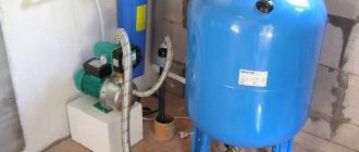
Piston compressors are used wherever a stationary or mobile source of compressed air is needed. The relay turns off the compressor motor when the pressure in the reservoir reaches a set value, and starts it again if the pressure in the receiver drops below the permissible value. It also releases excess air into the atmosphere.
Principle of operation
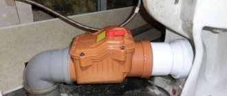
The operating principle of the automation unit is simple. The device is mounted on a pipe communicating with the receiver. The spring-diaphragm pressure switch sensor for the compressor continuously measures the pressure. As soon as it drops below the set value, the sensor rod, under the action of a spring, closes the contacts of the compressor relay and the electric motor is connected, pumping air into the tank. After reaching the set pressure, it presses the rod and opens the contacts, turning off the engine. Adjustment of these values is available to the user. In addition, when the operating pressure limit is reached, the safety valve included in the device is activated, releasing excess air from the compressor into the atmosphere.
The second way to regulate pressure
Another method, which is sometimes much more convenient and practical than the first, is adjustment through a gearbox. A reducer is a device that takes in air already in a compressed state. This air must be transferred to the final apparatus.
These devices, gearboxes, also have a control element in the form of a valve. The pressure control range can be controlled, and the indicators depend on the power and capabilities of the compressors that are connected to the gearbox.
There are special models with the function of conveniently adjusting the supplied air pressure for each specific working tool. Sometimes such devices even have an option that relieves excess pressure, eliminating the excess and maintaining the safe, uninterrupted operation of any connected tool.
Device
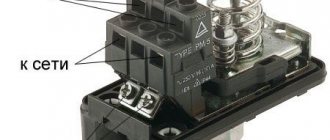
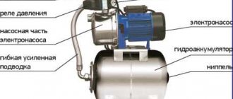
All components of the compressor pressure switch are assembled in a compact unit, covered with a plastic or metal case. The product includes:
- Inlet and outlet pipes.
- The sensitive element is a spring and a membrane.
- Stock. Connected to the membrane and placed inside the spring coils.
- Contact Group.
- Adjustment screws.
- Unloading and safety valve.
- Mechanical switch.
The elasticity of the spring, and, consequently, the sensitivity of the sensor, depends on the ambient temperature; most devices are designed to operate in the temperature range from -5 to +70 °C.
The unloading unit is designed to release air from the compressor cylinders after it stops. Thereby:
- its subsequent launch is facilitated;
- wear of piston group parts is reduced;
- the service life of the entire unit is extended.
When the unloading valve is activated in the silence that follows after the compressor stops, a sharp characteristic sound is clearly audible.
The mechanical switch serves for the initial start and final stop of the compressor. It has two positions: “On” and “Off”. “On” activates automatic operation systems. It transfers further control of the compressor to the pressure switch. The “Disabled” position prevents spontaneous starting of the motor when the pressure in the receiver drops below the set value.
The safety valve allows you to release excess pressure into the atmosphere in the event of a relay failure and avoid compressor breakdown in this case.
A thermal relay can serve as additional protection for the compressor motor. It is included in the automation unit; it disconnects the motor windings from the supply voltage in the event of an increase in current strength, indicating an overload of the motor.
Setting up an air compressor comes down to setting the operating pressure with an adjusting screw. The pressure regulator has values marked on it. Pressure can be controlled more accurately using a pressure gauge.
Operating principle
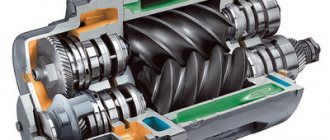
The pressure switch for the compressor controls the piston unit and maintains optimal pressure inside the receiver. Sometimes you can find such a unit on screw devices - it will be responsible for performing compression of air masses and their correct supply.
Taking into account the force of the pneumatic automation press, the device acts on the live line. Lack of pressure starts the motor, and when the specified parameters are reached, it turns it off. We are talking about a standard operating scheme, which involves connecting to a closed circuit network.
The role of the air pressure switch
The design of the ejector includes an air-filled cylinder with a given pressure. A decrease in performance requires turning on the engine and restoring the level. In the reverse situation described above, an excess will be recorded. The air supply will stop, otherwise the container will burst. The pressure switch is responsible for controlling these processes.
How do stiffener springs work?
There are modifications with a different working algorithm. By achieving minimum values in the compression circuit, the pressure switch turns off the electric motor, and at maximum values, it activates it. That is, the system operates only in an open circuit of the device.
The main working unit is springs with different stiffnesses. They reproduce the standard reaction to oscillatory movements inside the node. During the operation of the system, the indicators that are obtained when compressing and stretching the springs, that is, changing their sizes and shapes, will be measured. The changes are monitored by a spiral equipped with a relay unit. It disconnects or connects power lines if necessary.
There is no regulatory influence in the spring blocks; the main effect is on the motor. The user can set the peak values that are optimal for themselves; as the maximum is reached, the spring mechanism is activated.
Types of pressure switch devices
There are two main versions of the device available. The pneumatic-mechanical part is identical; the difference is determined by the method of closing the contacts when the rod moves:
- Normally closed (NC). used for direct control of low and medium power motor circuits.
- Normally open (NO). The movement of the rod closes the contacts when the maximum pressure is reached. The reverse movement opens them as it decreases. The contacts are used to control a more powerful relay that starts and stops the electric motor. The circuit turns out to be more complex, but the load on the pressure switch contacts is reduced and the service life increases.
When replacing a relay, you must carefully check that its type matches the electrical circuit of the compressor. his type.
Installation of relays and auxiliary elements
In addition to basic components, devices are often equipped with additional devices that increase ease of use or expand the functionality of the device.
They are installed on flange connections, most often 1/4”
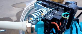
The pressure switch is connected to the compressor as follows:
- Screw the inlet pipe to the tank pipe.
- Connect a pressure gauge, unloading and safety valves to the flanges of the device.
- Close unused holes with plugs.
- Connect the electrical connector of the relay to the electric motor.
Low-power electric motors are connected directly; more powerful ones will require the use of a starter. The design of the pressure switch must match the engine power.
Adjustment and commissioning process
The device is configured and adjusted at the manufacturer's factory. Typical values are 2.8 atm. for the upper limit and 1.4 for the lower limit. However, sometimes situations arise in which it is necessary to adjust the device yourself:
- Setting up after partial or complete repair.
- Specific requirements of consumer devices.
- Installing a relay that was not originally designed to work with this compressor.
Before you begin adjustment, you should carefully study the parameters of all mating devices according to their data sheets. Passport data must correspond to the numbers embossed or engraved on a plate attached to the body of the unit.
The main indicator is the maximum pressure for which the compressor is designed. The value at which the pressure switch will operate should be 0.4-0.5 atm less than this maximum. In real operating conditions of the device, taking into account voltage instability, losses in seals, and the degree of wear of the piston group, this pressure may not be achieved. Then the pressure switch will not turn off the motor, the compressor will work continuously, overheat and wear out.
Having decided on the parameter values, you can begin making adjustments. To do this you need:
- Remove the casing.
- Two nuts will become available - a larger one and a smaller one. These are the regulatory bodies. Arrows are engraved on the body nearby, showing the direction of rotation to increase and decrease the parameter, respectively.
- The large nut sets the value at which the electric motor turns off. When rotated clockwise, the value increases, in the opposite direction it decreases. It is indicated by the P (Pressure) icon.
- The smaller nut sets the difference in engine start pressure compared to the shutdown value. It is designated ΔР.
Before you start setting up, you should fill the tank at least 2/3 full. The sequence of actions is as follows:
- Disconnect the unit from the network.
- Adjust the P and ΔP values by rotating the adjusting nuts.
- The set values should be monitored using a pressure gauge.
A number of manufacturers place adjustment controls on the outside of the device. This increases the convenience of adjustment, but at the same time increases the risk of changing the settings by accidental touch.
Setting up the expansion valve
The factory setting of a correctly selected and correctly installed thermostatic expansion valve will in most cases satisfy the needs of the respective system. The superheat at the evaporator outlet should be about 8-10 K. If it is necessary to adjust the expansion valve (additional adjustment), use the adjusting screw. To measure the superheat at the evaporator outlet, it is necessary to install a thermometer on the surface of the pipe at the evaporator outlet and connect the pressure gauge to the suction line. The difference in the readings of the pressure gauge on the temperature scale and the thermometer is overheating.
REMEMBER! When the screw is rotated to the right (clockwise), the overheating increases . When rotated to the left (counterclockwise), it decreases . A full turn of the screw changes the superheat by approximately 4 K for expansion valves of type T2 and TE2 and by 0.5 K for expansion valves of type TE5 at an evaporation temperature of 0°C. If liquid refrigerant enters the compressor (superheat below 7 K) or pulsation of the expansion valve is observed, it is necessary to increase the superheat .
When setting up a TE5 type expansion valve, in order to avoid overfilling the evaporator with liquid, you must proceed as follows (see Fig. 8-2.a). By rotating the adjusting screw to the right (clockwise), increase the superheat until the pressure pulsations stop. Then gradually turn the screw to the left until the pulsation begins. After this, turn the screw to the right about one turn. With this setting, there are no pressure pulsations and the evaporator operates in optimal mode. Changes in superheat within the range of ±0.5°C are not considered as fluctuations.
If the evaporator is overheating, this may be due to insufficient liquid supply. You can reduce overheating by rotating the adjusting screw to the left (counterclockwise), gradually reaching the pressure pulsation point (see Fig. 8-26). After this, turn the screw to the right one turn. With this setting, pressure pulsations stop and the evaporator operates in optimal mode .
Source
Possible malfunctions of the device
The device is characterized by its simple design and high reliability. However, they are also subject to malfunctions and breakdowns. A number of minor difficulties can be easily corrected with your own hands:
- Air leakage from the device when the pump is turned on. Identified by a characteristic whistle and the feeling of a sharp cold draft near the body. Most often the cause is a broken start valve. To repair, the gasket must be replaced.
- Frequent starting of the motor. The cause may be loose adjustment screws. It is necessary to carry out the procedure for adjusting the on and off threshold values using the pressure gauge and, if necessary, restore the passport values.
In case of serious problems, experienced technicians recommend not to bother with repairs and subsequent adjustments, but to immediately replace the entire device.
Troubleshooting methods
More complex work will be required if the compressor does not turn on. This can happen if the relay contacts wear out and melt from sparks that occur when the electric current is interrupted. Two methods are possible:
- In case of slight wear of the contact groups, clean the areas with a file or sandpaper. Care must be taken not to bend the slats. This will extend the service life by several weeks.
- Replace the contact groups with new ones from the repair kit for this model.
To repair contact groups, the following operations should be performed:
- Bleed the air from the tank and disconnect the unit from the network.
- Remove the relay from the compressor.
- Remove the casing.
- Disconnect the wires going to the contacts.
- Using a screwdriver, pry the contact terminal out of the mount and carefully drill out the melted areas.
- The wire is replaced with copper wire of the appropriate cross-section. It should fit into the hole with minimal clearance. The wire is passed into the hole and pressed tightly with pliers.
- After repairing all melted contacts, reassemble the device in the reverse order.
It makes sense to spend time on such repairs only if branded spare parts are unavailable for replacement.
Handicraft production
Making a relay yourself in a garage is very difficult. You must have ingenious knowledge and possess complex technologies in your workshop. The operation of the device is based on the principle of operation of the mechanism when electric current passes through special elements. These elements, at a certain current value, heat up, turning the mechanism on or off. Even an experienced electrician will find it difficult to make such a mechanism. When making a homemade compressor, old refrigerators are used, which always have their own relay.
Connection diagram
The connection diagram for the pressure switch depends on the type of electric motor. Single-phase ones are controlled by relays designed for 220 V with two contact groups. For three-phase electric motors, a 380 V device is installed, with three contact groups, each connecting its own phase. The use of single-phase switches for three-phase loads is unacceptable, since one of the phases remains permanently connected to the winding.
Flange connections
A number of manufacturers install additional flange connectors on their products. Most often there are two or three of them, the standard size is ¼ “. Through them, components such as a safety valve, pressure gauge, etc. are connected.
Installing a pressure switch
For installation, you must perform the following operations:
- Connect the relay to the receiver pipe.
- Connect the pressure gauge, safety and relief valves through the flange connectors.
- Place plugs in the remaining unoccupied connectors.
- Connect the wires from the engine to the electrical connector of the device.
- Make adjustments.
The last point should be considered in more detail.
Relay adjustment
Important! The adjustment is carried out with at least 2/3 of the tank filled and the power turned off.
The manufacturer supplies devices that have been tested and adjusted to standard values. If the parameters of a given compressor or the characteristics of consumer devices require you to configure the relay to other values, you should do the following:
- Remove the device cover.
- Two wrench heads will become visible.
- The big one controls the shutdown pressure and is designated by the letter P (Pressure).
- The small one controls the pressure difference at which the motor turns on. It is designated by the letters ΔP.
- The arrows indicate the direction of rotation for increasing values (+) and decreasing values (-).
- Control the pressure using the pressure gauge and set the required values.
Next, you should reassemble the device in reverse order. The compressor is ready for operation.
Source
Air relay connection diagrams
The compressor pressure switch is manufactured for connection to electrical circuits of different loads. In accordance with the rating of the power supply line, the appropriate model of the relay unit is selected.
Option #1: to a network with a nominal value of 220 V
If the drive motor is a single-phase device, then a 220 V relay with two groups of contacts is installed.
Read also: How to test an ultraviolet LED
Option #2: to a three-phase network with a voltage of 380 V
For a three-phase load of a 380 V circuit, one of the options can be used: a modification of the relay for 220 V or 380 V, with three contact lines, to simultaneously disconnect all three phases.
Both methods have different schemes. Let's consider the first option:
By choosing the second method, power is supplied from one phase (zero) and in this case the relay rating should be 220 V. For more details, see the following diagram:
After connecting to the power supply, you need to understand the additional capabilities provided in the air blocks for ejectors.
Pressure switch for a compressor: independent connection and configuration
In most cases, inexpensive models of air compressors are not equipped with a pressure switch, since such products are mounted on the receiver. Based on this, many manufacturers think that visual monitoring of pressure using a pressure gauge will be more than sufficient. However, during long-term operation of the device, if you do not want to cause the engine to overheat, it makes sense to install a pressure switch for the compressor! With this approach, the drive will be turned off and started automatically.
What is a pressure switch?
Pressostat is a pressure switch for a compressor, the main component of compressor automation. He is responsible for starting and stopping the system if it reaches the specified air mass supply parameters. As the required values are obtained, the following operations occur:
- the engine turns on when the pressure is critically high;
- The system shuts down if the pressure is unacceptably low.
That is, the compressor pressure switch regulates the operating process of the system from the moment it is turned on until it is completely turned off. It does not allow the compressor to operate under increased loads and prevents its premature wear. In many ways, the success of the system depends on the coherence of all its components: the air reducer, pressure gauges, supply-type communications (fittings, tubes), the relay itself.
Circuit and device
The device is divided into the following types:
- Starting the electric motor of the compressor when the pressure drops below the set value (normally closed);
- Switching off the engine when the air pressure rises above the normal level (normally open).
The executive element in the device is springs. Their compression force is measured using a special screw. As a rule, manufacturers adjust the compression force of the springs so that the pressure in the pneumatic network is in the region of 4-6 at. This parameter is always precisely indicated in the instructions.
Since the flexibility and stiffness of springs always largely depends on temperature, all elements of industrial pressure switches are designed and created taking into account subsequent operation at temperatures from minus 5 to plus 80 degrees.
The pressure switch includes 2 mandatory subassemblies in its design - a mechanical switch and a relief valve. A mechanical switch protects against accidental starting of the engine, thus performing the stand by function. After pressing, the device drive starts, after which the compressor begins to operate in automatic mode. Without pressing the button, the electric motor will not work even with reduced pressure in the pneumatic network.
The unloading valve is connected to the air supply line between the compressor and the receiver and is responsible for engine operation. When the compressor drive is turned off, the unloader valve on the receiver gets rid of excess compressed air, thus relieving the moving parts of the extra effort required when restarting the compressor. This eliminates overloading of the engine during torque. When the unloaded engine is turned on, the valve closes, which prevents unnecessary load from being created.
Purpose, design features and scope of application
There are quite a large number of protective safety devices that can significantly increase the service life of the compressor. The device in question has design features that make it possible to control the movement of the medium in only one direction. In other words, the valve prevents the reverse flow of compressed air, for example, when the device stops operating. The check valve for the compressor is represented by a combination of the following elements:
- Metal body. It is characterized by high resistance to environmental influences.
- Rubber ring.
- A spring that fits over the guide lugs.
- A plug that ensures the mechanism is closed.
- Sealing gasket. It significantly increases the degree of tightness of the check valve.
- Hole for connecting the compressor unloading valve.
A similar compressor check valve device is designed to relieve excess pressure in the system, as well as prevent return air flow. The design is also made by hand to achieve a similar goal. The operating principle is characterized by the following features:
- Air under pressure is supplied to the inlet. It can have a wide variety of diameters.
- The created pressure compresses the spring, due to which the passage hole opens. The spring is made of a special corrosion-resistant material, which ensures a long service life.
- When the compressor is turned off, the spring returns to its position and the line is closed. Due to this, the possibility of reverse flow of the medium is eliminated.
The above information indicates that the design of the mechanism is quite simple and reliable in operation. The purpose and features of the mechanism determine its very wide distribution.
Connecting and setting up a pressure switch
The pressure switch in the compressor installation circuit is located between the secondary engine control circuit and the unloader valve. As a rule, a pressure switch for a compressor is equipped with 4 threaded heads, one of which is intended for connecting the control pressure gauge, the second for connecting the device to the receiver. A ¼-inch threaded plug is installed on one of the remaining ones, and a safety valve is installed on the last one. The presence of a free connector makes it possible to place the control pressure gauge in the most convenient place.
The pressure switch is connected in the following order:
- A device is connected to the unloading valve of the receiver.
- A control pressure gauge is placed. Otherwise, the threaded entry is plugged.
- The motor control circuits are connected to the terminal contacts. If the network voltage changes, then the connection should be made through a surge protector! This is also necessary when the contact power exceeds the indicator for which the engine is designed.
- The compressed air pressure readings can be adjusted if necessary using adjusting screws.
Before connecting the pressure switch to the compressor, it is worth checking that the network voltage corresponds to what is specified by the manufacturer! For example, a two-contact group is used for a three-phase network with a voltage of 220V, a three-contact group is used for a voltage of 380V.
The setup is performed with the receiver at least 2/3 full. To do this, the relay is disconnected from the power supply, after which, with the cover removed, the compression of the springs is adjusted. The maximum operating pressure is determined by the adjusting screw with the axis of the larger spring. The second adjusting screw, with a smaller spring, allows you to adjust the pressure difference. In most cases, the manufacturer indicates on the board the direction of rotation for increasing and decreasing pressure. Here you can also see the generally accepted designation for pressure - the Latin letter “P” and “ΔP”.
In some models, to reduce the time required to adjust the pressure, the manufacturer places the adjusting screw outside the pressure switch housing. In this case, the result is controlled based on the pressure gauge readings.
Purpose
The function of air compressors is to produce a stream of air with a certain pressure; it must be stable and uniform. It should also be possible to change the parameters of this jet. Each compressor has a reservoir (cylinder) for air. It must have the required pressure. When it drops, turn on the engine to replenish the air supply. If there is excessive pressure, the air supply should be stopped to prevent the container from bursting. This process is controlled by a pressure switch.
Pressure switch device RDM-5
When it functions correctly, the engine is preserved, it is protected from frequent switching on and off, and the operation of the system is uniform and stable. The container membrane is connected to the pressure switch. By moving, she can turn the relay on and off.
Principle of operation
Taking into account the amount of pressure in the system, the relay serves to open and close the voltage circuit; if the pressure is insufficient, it starts the compressor and turns it off when the parameter rises to a predetermined level. This is a normally closed loop operating principle for motor control.
The opposite principle of operation is also encountered, when the relay turns off the electric motor at minimum pressure in the circuit, and turns it on at maximum. This is a normally open loop circuit.
The working system consists of springs of different levels of rigidity that respond to changes in pressure. During operation, the deformation forces of springs and compressed air pressure are compared. When the pressure changes, the spring mechanism is activated and the relay closes or opens the electrical circuit.
Accessories
The air compressor relay may contain the following components:
- Unloading valve. It is located between the compression chamber and the compressor check valve. When the engine stops, this component is activated and removes excess pressure from the piston block. When the engine starts, the pressure generated closes the valve, making it easier to start the unit. Some unloader valves have delayed activation. When starting the engine, it assists the engine by remaining open until the system reaches a predetermined value. During this time, the engine reaches maximum speed.
- Mechanical switch. Serves to enable and disable automation. The switch usually has two positions. When the mode is turned on, the automation is activated, the compressor is connected to the network and turned off, taking into account the specified pressure parameters in the system. In the OFF position, no power is supplied to the drive.
Pressure switch for air compressor
- Thermal relay. It protects the electric motor by limiting the current so that the motor windings do not burn out. The required current strength is set using a regulator. If the set value is exceeded, the engine will be disconnected from the network.
- Safety valve. Protects the system in case of improper functioning of the pressure switch. When the pressure is exceeded, if the relay does not operate, the safety valve is activated, which relieves the pressure. This allows you to avoid accidents when the control breaks down.
Detailed description of the pressure switch for the compressor (video)
DIY pressure switch
If you have a working thermostat at home from an old refrigerator, as well as some operating skills, then you can easily make a pressure switch for the compressor with your own hands. However, it is worth warning in advance that such a solution will not have great practical possibilities, since the upper pressure with such an approach will be limited only by the strength of the rubber bellows.
It is most convenient to convert the KTS 011 thermal relay into a pressure switch, because they differ in the reverse operating sequence - when the temperature in the chamber decreases, they turn off, and when the temperature in the chamber increases, they turn on.
Work order
After opening the cover, the location of the required group of contacts is determined, and for this purpose the circuit is ringed. The first step is to modify the connection of the compressor with the thermal relay: the contact groups are connected to the terminals of the electric motor circuit, and the unloading valve is connected to the outlet pipe with a control pressure gauge. The adjusting screw is located under the thermal relay cover.
When the compressor starts, the screw rotates smoothly, at the same time you need to monitor the pressure gauge readings. It is worth making sure that the receiver is 10-15 percent full! To achieve minimum pressure, it is necessary to smoothly move the face button rod. For this purpose, the cover is placed in its original place, after which the adjustment is performed almost blindly, since there is nowhere to install the second pressure gauge.
For safety reasons, it is not recommended to set the thermostat pressure beyond 1-6 atm! If you use devices with a stronger bellows, the maximum range can be raised to 8-10 at, which is usually enough for most tasks.
The capillary tube is cut only after you are sure that the relay is working. After releasing the refrigerant inside, the end of the tube is placed inside the relief valve and sealed.
The next step is to connect a homemade pressure switch for the compressor to the control circuit. To do this, the relay is fixed to the control board with a nut. The locknut is screwed onto the thread on the rod, thanks to it you can subsequently adjust the air pressure.
Taking into account the fact that the contact group of a thermal relay from any refrigerator is designed to work with high currents, they can switch fairly powerful circuits, for example, secondary circuits when working with a compressor motor.
Source
Design and principle of operation of the automation unit
To maintain the pressure in the receiver at a certain level, most air compressors have an automation unit, a pressure switch.
This piece of equipment turns the engine on and off at the right time, preventing the compression level in the storage tank from being exceeded or too low.
The pressure switch for the compressor is a unit containing the following elements.
- Terminals. Designed for connecting electrical cables to relays.
- Springs. Installed on adjusting screws. The pressure level in the receiver depends on the force of their compression.
- Membrane. It is installed under the spring and compresses it under the action of compressed air.
- Power button. Designed to start and force stop the unit.
- Connection flanges. Their number can be from 1 to 3. The flanges are designed for connecting the compressor start relay to the receiver, as well as for connecting a safety valve with a pressure gauge to them.
Conclusions and useful video on the topic
Details about the design of the pressure switch, as well as a visual process for adjusting its parameters in the plot:
It is also possible to independently assemble the control unit for the compressor; see this video:
Pneumatic devices are considered safer and easier to use than electric or gasoline models. There is a wide selection of additional equipment that works with compressed air: guns for washing, inflating tires or painting and many others.
With the help of a relay, it becomes possible to operate automatically while maintaining the required compression level in the receiver.
Please write comments in the block form located under the article test. Share your own experience in operating a compressor with a pressure switch, ask questions, post photos on the topic. It is possible that your recommendations will be useful to site visitors.
Diagrams for connecting the pressure switch to the compressor
The connection of the relay that controls the degree of air compression can be divided into 2 parts: the electrical connection of the relay to the unit and the connection of the relay to the compressor through the connecting flanges. Depending on which motor is installed in the compressor, 220 V or 380 V, there are different connection diagrams for the pressure switch. I am guided by these diagrams, provided that you have certain knowledge in electrical engineering, you can connect this relay with your own hands.
Connecting the relay to a 380 V network
To connect the automation to a compressor operating from a 380 V network, use a magnetic starter. Below is a diagram of connecting automation to three phases.
In the diagram, the circuit breaker is indicated by the letters “AB”, and the magnetic starter by “KM”. From this diagram it can be understood that the relay is set to a switch-on pressure of 3 atm. and shutdown - 10 atm.
Connecting the pressure switch to a 220 V network
The relay is connected to a single-phase network according to the diagrams given below.
These diagrams indicate various models of pressure switches of the RDK series, which can be connected in this way to the electrical part of the compressor.
Connecting the pressure switch to the unit
Connecting a pressure switch to a compressor is quite simple.
- Screw the pressure switch onto the receiver pipe using its central threaded hole. For better thread sealing, it is recommended to use fum tape or liquid sealant. The relay can also be connected to the receiver through a reducer.
- Connect a relief valve to the smallest output from the relay, if present.
- The remaining outputs from the relay can be connected to either a pressure gauge or a safety relief valve. The latter is installed without fail. If a pressure gauge is not required, then the free output of the pressure switch must be plugged with a metal plug.
- Next, wires from the electrical network and from the engine are connected to the sensor contacts.
After the complete connection of the pressure switch is completed, it is necessary to configure it for proper operation.
Structure of pneumatic relay symbols
The marking of the air pressure switch indicates the entire optional set of the device, design features, including information about the factory settings for the pressure differential.
Condor's production models offer a wide range of pressure control equipment. The MDR series is aimed at using ejectors of various powers
Let us examine the designations in more detail using the example of devices for air ejectors RDK – (*) (****) – (*)/(*):
- RDK – series of relays for compressors;
- (*) – number of threaded ports: 1 – one port with 1/4”NPT internal thread; 4 – four connectors;
- (****) – type of housing design: T10P – version 10 with a “lever” switch; T10K – “button” switch; T18P – execution 18 with a “switch” switch; T19P – 19 s;
- (*) – factory settings of the threshold response: 1 – 4…6 bar; 2 – 6…8 bar; 3 – 8…10 bar;
- (*) – diameter of the unloading valve: the absence of a symbol means a standardized parameter of 6 mm; 6.5 mm – 6.5 mm.
The difference between the minimum and maximum pressure thresholds is set by the manufacturer and, as a rule, has a value of 2 bar.
However, it is also possible to manually adjust the range of two values – maximum and minimum, but only downward.
The specifics of setting up pressure switches for pumping stations are outlined in the following article, the contents of which we recommend that you familiarize yourself with.