How are major components overhauled?
Overhaul of main components is carried out with the aim of restoring serviceability, complete or close to full restoration of the resource, with replacement or restoration.
Restoration of guides
Guides are one of the least worn parts of a lathe. Depending on the degree of wear, there are several methods of overhaul.
Scraping
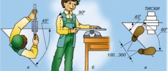
If the error is less than 0.15 mm per 1000 mm of length, restoration is performed by scraping. The frame is installed on a repair stand and secured strictly in a horizontal plane. Scraping is carried out in three stages. The roughing pass is performed with a scraper with a working width of 20–30 mm.
Semi-finish scraping is performed with a scraper of 11–18 mm, finishing (finishing) scraping is performed with a scraper with a working width of 5–10 mm. Since the machine guides are long, scraping occurs along the beacons. This method makes it possible to obtain high processing accuracy (up to 0.002 mm per 1000 mm) and is used for non-hardened guides.
Grinding
Grinding is used for hardened guides, and also, if necessary, to speed up the repair process. Processing is carried out with a cup grinding wheel, making it possible to carry out repairs without disassembling the machine. Sanding is a much more productive process than scraping. This method allows you to obtain high accuracy and low surface roughness of the guides.
Planing
In case of serious wear (more than 0.15 mm per 1000 mm), the guides can be corrected by planing. Processing by planing according to the duration of the operation is the fastest method. However, the duration increases during transportation. Planing is carried out in two stages: rough planing aligns the guides, and finishing (minimum 2 passes) removes an additional layer of metal.
bed
As for the bed, it is necessary to eliminate inaccuracies that arise when the guides wear out. The specific restoration method chosen in a particular situation depends on one degree or another of wear. If there is an inaccuracy of 0.15 mm per 1 meter, scraping is used; if it is large, restoration is carried out by planing or grinding.
Tailstock
The tailstock is used to secure the workpiece and tool. This is one of the most used components of the machine. During repairs, the connection between the headstock and the frame should be restored, the play should be eliminated, and the accuracy of the hole and the location of the centers should be checked.
In case of malfunction, replace or repair the quill and feed screw. The hole for the quill is repaired by lapping (low-worn holes), boring with adjustment and acrylic plastic (the most effective and economical method).
Repairing the caliper carriage
When overhauling the carriage of a lathe, it is necessary to restore its lower guides that mate with the guides of the bed. Also, when restoring this mechanism, it is necessary to eliminate the play between the guides. The caliper guides are repaired by grinding and scraping. After a major overhaul, the carriage must be correctly aligned.
Lead screw and lead shaft
Often, during repairs it is necessary to restore the alignment of the lead screw, shaft, apron and feed box. To do this, the feed box is fixed on the frame, we install the carriage and attach the clamping bar. We install the frames into the holes of the feed box, and connect the apron to the carriage. We move the carriage towards the feed box until the frames touch. We measure the resulting clearance with a probe.
Repair by scraping
Scraping of guides or scraping followed by lapping remains the most effective way to restore their geometric and technical accuracy. And now this method is often used, demonstrating excellent results in machine bed repair for many decades. First of all, it is necessary to examine the condition of the guides and determine the degree of their wear. The place where the wear is minimal is taken as the base level, and the measurement data is entered into a table, on the basis of which repairs will be made. In a lathe, the base surface is most often taken to be the location of the tailstock, which practically does not wear out during operation of the equipment. The method includes the following steps:
Since the guides of the lathe bed are quite long, processing is carried out along the beacons, dividing the total length into sections. The first beacon is always the place of maximum production. At a distance less than the length of the straight edge from the first beacon, a second beacon is scraped, located in the same plane as the first. Then the entire surface between the beacons is scraped, followed by moving to the adjacent area. Periodically, apply a ruler with paint to assess the condition of the guides and the quality of work.
Watch the video of rough scraping
Non-hardened parts of lathe guides are subjected to this treatment; the method guarantees the achievement of high surface accuracy (0.002 mm per 1000 mm length). The tiny holes formed after scraping are able to hold the lubricant well and distribute it evenly. The quality of scraping depends entirely on the professionalism of the worker.
Possible faults
Drilling machine on a magnetic sole: types and features of magnetic machines
During long-term operation of turning equipment, the parts of its mechanisms lose their original qualities, which leads to a change in their shape, an increase in gaps at the mating points and a deterioration in the condition of the friction surfaces. One of the main reasons for the occurrence of such malfunctions is wear of the friction surfaces of individual parts, which occurs as a result of:
- influence of friction force;
- plastic deformation (metal collapse);
- surface layer fatigue;
- chemical corrosion.
Possible malfunctions of the main elements of the lathe:
- Case parts. Cracks, chips, wear of holes, damage to threads, deviation from straightness of planes.
- Shafts. Wear of journals, keyways, center holes.
- Flanges. Cracks and chips in mounting holes. Wear of mating surfaces.
- Gears and pinion shafts. Tooth wear and radial runout of the ring gear.
- Spindle. Worn journals, front inner cone and spline joint.
- Lead screw. Wear of threads and journals.
- Running roller. Wear of the keyway and journals.
Machine design 16K20
Based on the inspection and control measurements of these 16K20 components, the need for repair is determined and preparations for repair and restoration work are carried out. Inspecting the machine for repairs begins with the pulley, which on a 16K20 lathe transmits motion from the main motor to the spindle. A list of the main problems that arise as a result of violations of the equipment operation rules is given in section 16 of the “Operation Manual.” Possible causes and methods for eliminating them are also indicated here.
The need for repairs and preparation for it
The most common situations in which repair of a turning unit, rather than maintenance, is required are wear of guides, bearings, failure of forks that switch elements of gear connections, etc. Naturally, after a period of prolonged operation, turning equipment needs a major overhaul, to which should be properly and thoroughly prepared.
The level of vibrations and noise emitted by worn-out components of a lathe is determined when the equipment is idling. In addition, the axial and radial runout of the spindle assembly is checked. To diagnose the condition of the rolling bearings, it is necessary to process a test workpiece and compare the obtained geometric parameters with the required values. In many cases, such actions allow you to avoid major equipment repairs and limit yourself to eliminating local faults.
If a major overhaul of a lathe is still necessary, before doing so it is necessary to thoroughly clean the equipment from dirt and dust that has accumulated during its operation. All technical fluids required for the operation of the machine (oil, coolant) must be drained. Then they check whether all structural elements of the equipment are in place.
Features of a major overhaul
The most popular types of lathes
When carrying out a complete inspection of the screw cutting machine, pay special attention to the following:
- Stanin. The bed is a connecting element and the accuracy of processing, the presence of vibration and much more depend on its condition.
- The support is designed to secure the tool and move it relative to the workpiece. Like other parts of the structure, it is subject to wear and tear.
- The apron is designed to convert rotational motion into reciprocating motion. The smooth running of the caliper will depend on its condition. Therefore, its condition is being checked.
- Gearbox and gearbox.
- On the operating features of all electrical equipment.
- Tailstock condition.
As a rule, all important parts of the screw cutting machine that are exposed to the greatest impact during processing of the part are subject to inspection.
After checking for defects, their correction is carried out by instrumental intervention or complete replacement of the worn-out element of screw-cutting lathes. For example, when restoring electrical equipment, it is often necessary to carry out a complete replacement, since the restoration work is very complex. When restoring a tailstock, only certain parts can be replaced.
Repair work is carried out exclusively by specialists who have the skills to disassemble and diagnose screw-cutting equipment. The testing stage allows us to find the most rational solution for restoring screw-cutting lathes.
Varieties and design features
There are actually a lot of machines and they perform all kinds of metal processing operations, but we will highlight the most famous types
Multi-incisor
Designed for processing complex parts made from pipes, shaped profiles or rods of different sections. Multi-cutter or multi-spindle machines are mainly used in batch production.
Performed operations:
- drilling;
- thread;
- turning;
- pruning;
- boring;
- countersinking;
- deployment.
Multi-cutting machines have high productivity due to the large area of the drive mechanism, rigidity of the structure, and the ability to perform several operations simultaneously.
Carousel
A group of machines for working with large-sized parts and workpieces. The parts processed on them are short in length, but have significant weight and diameter.
Features of carousel models:
- used for processing conical or cylindrical surfaces;
- grooves of various configurations are made;
- You can also do grinding, milling, trimming ends;
- thread cutting.
In addition to the basic elements of any lathe, this type has additional equipment:
- table with faceplate;
- racks for moving the traverse.
Backing
The machines are designed for processing the back surfaces of tool teeth. It can also be used to perform other turning operations. The backing machine is distinguished by its special support design. The part is backed up as follows:
- rotational movement of the part;
- reciprocating movement of the cutting tool towards the part.
Screw-cutting
The most common group of machines. Widely used in serial and individual production. Screw-cutting models can be found in workshops, schools, and in any industry. They are easy to operate and maintain.
REFERENCE! The screw-cutting lathe is a universal model for all kinds of processing of metal workpieces. It can be used to make various types of threads: modular, inch, metric.
Structural elements:
- bed;
- front and rear stock;
- caliper;
- apron;
- gearbox.
Revolver
Revolver group machines are designed for processing parts from calibrated rods. Operations that can be performed on this equipment:
- turning;
- boring;
- shaped turning;
- countersinking;
- drilling;
- thread formation;
- deployment.
REFERENCE! The name of the machines in this group comes from a special holder. It can be driven or static. The drive type gives more possibilities for carrying out various operations.
Universal
Universal lathes include screw-cutting machines, since they can perform almost any metal operation.
Main technical characteristics of the universal machine:
- rotation speed (number of revolutions); accuracy class; it is indicated in the product labeling with the letters S, B, N, A, P;
- number of gears;
- what sizes of parts can be installed;
- weight and dimensions of the machine;
- the amount of feed and maximum movement along the axis.
What is turning?
Purpose and types of rotating centers for lathes
The technological process of turning consists of reducing the diameter of the workpiece using a cutter, which is equipped with a special cutting edge.
Due to the rotation of the workpiece, the cutting process occurs; feed and lateral movement are carried out by the cutter.
Thanks to these three components: rotation, feed, movement, it is possible to influence the amount of material removal; the quality of the machined surface, the shape of the chips, etc. also depend on this.
Basic elements of a lathe:
These elements are the main ones; depending on the modifications, you can get centering, turret lathe, multi-cutting and other machines that must undergo mandatory maintenance.
Typical control unit
When considering a modern universal screw-cutting lathe, you should pay attention to the control unit. To indicate the main processing parameters, levers and handles, buttons and other control units are installed
The main features include the following points:
- As a rule, a handle is installed to indicate the number of revolutions. A universal modern screw-cutting lathe can change this indicator, which is selected depending on the required cutting conditions.
- A screw-cutting lathe has a device that allows the formation of a threaded surface. Its parameters are set using a special control unit. Do not forget that some parameters can be set solely by installing the required replacement wheels.
- There are also handles that allow you to control the caliper. Screw-cutting lathes have main components that allow mechanical feed for quick positioning and processing with a constant movement speed.
Controls of screw-cutting lathes using the example of model 16K20
The CNC screw-cutting lathe has a more complex layout. This is due to the fact that such equipment can operate without operator intervention at intermediate stages.
Possible faults
The most common cause of malfunctions is natural wear and tear of parts and mechanisms. A lathe consists of many moving parts driven by bearings. Failure to replace bearings in a timely manner may result in machine failure. Overheating of the machine occurs when the load is higher than permitted, violation of the work and rest regime (work without a break). Electrical faults can also cause overheating.
The machine turns off during operation - you should check the condition of the electric motor brushes, or reduce the load (by reducing the speed and feed). A lack of coolant flow can occur when the fluid level is low or the pump is broken. If the tension of the belt drive is loosened, the speed of rotation will decrease during operation. Replacing the belt and adjusting the friction clutch will help get rid of this problem.
Inaccurate processing can also be a consequence of machine malfunctions. For example: play of the tool holder or chuck on the spindle. By following machine maintenance rules, maintaining cleanliness in the workplace and carrying out preventive maintenance on time, you can reduce breakdowns.
Types and features of repair work
The classification of all repair work carried out is carried out on the basis of a system of planned preventive maintenance (PPR). This complex includes:
- technical (overhaul) maintenance – ensures the operation of the machine between repairs. Maintenance involves caring for the equipment in use and minor repairs. Can be performed by machine operators and mechanics on duty;
- current repairs are carried out during the operation of the equipment to ensure its guaranteed performance. During the repair process, parts of the machine are replaced or restored, as well as the necessary adjustments and adjustments;
- major repairs - carried out to restore the serviceability of equipment. When performing a major overhaul, it is possible to replace the main components of the machine;
- Unforeseen breakdowns and emergencies are eliminated during unscheduled repairs. In this case, only damaged elements are replaced or restored.
Preparatory work
Before starting repair work, it is necessary to identify and determine all faults. To do this, the machine must be carefully inspected, checked for accuracy, read the entries in the fault logs, and assess the scope of repairs. It is necessary to study the structure of the machine by reading the drawings and technical data sheet.
It is important to correctly determine the order of disassembling the mechanisms and allocate a suitable place for this. We clean the machine from dust and technical liquids and prepare the tools necessary for repairs
The last step is to turn off the power to the equipment and post a warning sign.
Small
Minor repairs are characterized by the replacement or restoration of a small number of worn parts or components. When performing minor repairs, the machine is checked for accuracy and cleanliness of processing, bearings are adjusted or changed, lead screws are cleaned, and worn fastening elements are replaced. If necessary, repair the coolant and lubrication supply system.
Average
During the average repair of a lathe, the unit components are disassembled, several components or mechanisms are replaced or restored, guides are polished, and adjustments and tests are performed under load. When carrying out mid-term repairs, a List of Defects is compiled.
Capital
The most complex and most expensive type of planned repair. Includes a complete disassembly of all components and assemblies of the machine with recording of noticed faults and deviations in the defect list, complete repair of the tailstock and spindle, replacement or restoration of all faulty units. As part of the overhaul, technical modernization of equipment may also take place in order to increase productivity and reduce defects.
Lathe rigging
Rigging work includes: loading, moving, unloading equipment.
The lathe has a large mass. Therefore, during work it is necessary to comply with technical safety rules. Lathes weigh from 300 kg to 5 tons
Before you begin rigging the machine, you need to make accurate technical calculations, measurements of units and openings, and take into account the technical characteristics of the equipment. Draw up a transportation plan so as not to clutter up the site where the lathe is planned to be installed and not to paralyze production.
Experienced specialists of our company will carry out professional rigging of the lathe using lifting equipment and equipment (turnbuckles, ropes, belts, slings, chains, trolleys, forklifts and truck cranes).
Basic rules for rigging work:
- The workspace must be equipped with flooring and racks for spare parts;
- Large elements are screened with a wooden frame and signal flags are glued on;
- Moving units are fixed in a static, stationary state;
- Auxiliary parts (nuts, fasteners) are packaged in separate cases with tags.
Lubrication of a screw-cutting lathe during maintenance
Mineral oils are used to lubricate the lathe, and solid oils are used for bearings. The lower the load and the higher the rotation speed, the less thick the lubricant should be. The required brand of lubricant is set by equipment manufacturers in accordance with the temperature to which the mechanism heats up during operation.
An example of a lubrication schedule and the choice of oil depending on the unit
In order not to make a mistake, it is necessary for each individual mechanism to determine the admissibility of using a certain type of solid oil in accordance with the technical data sheet.
For lathes, 4 methods of lubrication of units are applicable:
- Circulation method - oil is supplied under the influence of a pressure pump, which forces the oil under pressure to circulate through a system of tubes leading to the units.
- Wick is one of the simplest and most reliable. In a lathe it is an addition to the crankcase option in case there is concern that the oil may not reach its target. A wick is inserted into the tube; it should be 6-8 mm from the surface onto which oil should fall at a certain frequency.
- Manual - in this method, lubricant is applied to bearings, carriage, screw and other open rubbing parts. Oil is poured into oil cans, and solid oil is injected into them using a syringe. This type of maintenance is carried out daily. If the machine is used intensively, it may require more frequent lubrication.
- The crankcase method is used to lubricate the gearbox, feed box and apron worm gear. The method is that oil is sprayed from a reservoir filled to a certain level by rotating gears. To monitor the oil level, there are control eyes and a tubular oil level indicator.
It is necessary to remember not only about the constant replenishment of lubricant reservoirs, but also that once a month it will need to be completely replaced. Before pouring a new portion of lubricant into the oil cans, it is necessary to remove the filters and gears from the tanks, and remove the wicks from the tubes. All this equipment must be washed and cleaned.
For the greatest effect, screw-cutting lathes often use all 4 types of lubricants at once, which makes it possible not to miss any of the components. Provided that technical equipment receives proper maintenance, its service life is significantly increased.
Machine repair: differences between current and major
Repairs, which any machine must undergo at certain intervals, can be routine or major. These types of repairs differ from each other in the goals pursued, the list of operations performed, labor intensity, duration and cost. Let's take a closer look at current and major types of machine repairs.
Current repairs are carried out in order to eliminate malfunctions of individual components and parts of the machine or restore them when worn. In the vast majority of cases, current repairs, otherwise called operational repairs, are carried out at the installation site of the machine, as well as in mechanical repair shops or production and technical departments of the enterprise. This repair, as a rule, is not specifically planned in terms of timing, which is explained by the impossibility of accurately predicting the time of failure of a particular machine component. The amount of work performed during routine repairs is not fixed: only average labor costs are planned, calculated in man-hours relative to 100 machine-hours.
Routine repair of machines can be carried out individually or as a unit. In the first case, components and parts that have failed are removed from the machine, restored, and then installed back. In the second case, damaged components and parts are replaced with new components, which were previously stored in a special exchange fund.
Damaged parts are sent to a mechanical repair shop, where they are restored and transferred to the exchange fund. An important advantage of the aggregate repair method is a significant reduction in equipment downtime and, as a result, an increase in product output. At the same time, the production area of RMM can be reduced, since the throughput of the workshops increases.
Major repairs of machine tools, as a rule, are carried out in a specialized repair organization (it, however, can be carried out without removing the machine - at the place of its operation). During a major overhaul, the equipment is disassembled into individual components and parts, which are classified into three groups of defects - serviceable, in need of repair and not subject to restoration. Then the equipment is assembled from replaced (new) and repaired parts, tested and run-in. The benefits provided by a major overhaul are quite significant:
- all characteristics of the repaired machine return to the passport accuracy standards;
- the quality of products manufactured on the machine is significantly improved;
- the degree of equipment safety in operation increases;
- the productivity of work and its convenience are increased, the time required for servicing the machine is reduced, and it becomes possible to increase its load;
- The enterprise saves money (compared to purchasing new equipment), and energy costs are reduced.
Overhaul of a machine is carried out in several stages, and it is extremely important to follow their sequence. First of all, the equipment is thoroughly cleaned of dirt (special wooden scrapers can be used for this). The machine is inspected and then disassembled. At the disassembly stage, defect detection of parts is carried out - searching for bends, cracks, chips, other breakdowns or signs of wear.
Disassembling the machine, in turn, is also performed in a strictly defined sequence. First, protective guards, casings, and covers are removed, after which specialists performing repairs gain access to failed components and parts of the machine. There are rules according to which equipment is disassembled:
- parts suitable for use are not disassembled (not depersonalized) in order not to damage their integrity and to facilitate subsequent assembly;
- parts installed with interference (bearings, gears, bushings, pulleys, sprockets, etc.) are removed using special devices - pullers, hydraulic presses, drifts. When installing these devices, distortions should be avoided, and sharp impacts should not be allowed when using them;
- components that have significant corrosion damage (rusted) are pre-soaked in diesel fuel or kerosene and only then disassembled;
- bolts and nuts are unscrewed with wrenches of the appropriate shape and size, screws are unscrewed with screwdrivers, the slots of which strictly correspond to the slots located in the heads of the screws;
- When disassembling rivet joints, the heads of the rivets are cut off with a chisel, and their rods are knocked out with a special bit.
All of the above rules must be followed to achieve the most important goal - to reduce the risk of damage to machine parts and components to a minimum.
Certain rules also apply to defective parts. Thus, the condition of the bearings is determined by the radial clearance, which is determined in two planes diametrically opposite to each other. The gears are checked by external inspection, and the degree of wear of the teeth, key and spline grooves is assessed.
To check the threaded parts of the parts, the latter are unscrewed or screwed in by hand in order to determine the difficulty of performing these operations. If parts are unscrewed or screwed in with difficulty, the thread is restored, and if this is impossible, the part is rejected.
Source
Repair of main components
bed
The 16K20 bed is a cast structure with stiffening ribs on which all other equipment of the lathe is mounted. On the top of the bed there are four longitudinal guides of the lathe: two flat and two prismatic. The positioning accuracy of the tailstock and caliper carriage, as well as the alignment of the front and rear stock, depends on the condition of their surfaces. The composition and procedure for performing the work is regulated by section 6.1 of the technical manual “Repair of a 16K20 screw-cutting lathe.”
There are four machining methods used to repair lathe guides:
- manual scraping;
- grinding using portable grinding equipment;
- grinding on surface grinding equipment;
- planing on a longitudinal planing machine;
https://youtube.com/watch?v=sJgzGG_6PU0
In general, if the wear is less than 15 microns per 1000 mm, the surface geometry is restored by manual scraping. If more, use machine tools or the spraying method.
In addition, only non-hardened surfaces can be treated with this method. It is possible to scrape the bed of a lathe without dismantling the bed, therefore, along with manual grinding, this is the most common method of restoring guide surfaces.
Grinding of guides using portable grinding equipment installed on the bed is used in two cases: if it is impossible to deliver the bed to the repair shop and if the length of the bed is greater than the length of the grinding equipment table. The most effective way to restore bed guides is processing on grinding and longitudinal planing machines in repair shops or at specialized enterprises. It provides the highest precision and guarantees quality.
Bed for machine 16K20
Restoration of deep damage to the lathe bed is carried out by spraying brass or zinc, as well as filling it with babbitt. After filling the dents and potholes with metal, the surface of the guide is processed by grinding or scraping.
Carriage
In accordance with section 6.2 of the Technical Manual, repairing the slide carriage of a 16K20 screw-cutting lathe includes two technological operations:
- restoration of the lower guides associated with the bed guides;
- restoration of the transverse guides adjacent to the guides of the lower part of the caliper.
Before starting work, the carriage is installed on the exposed bed along with the rack and feed box. After this, clamping bars, an apron, a lead screw and a running shaft are mounted on the carriage, it is set for accuracy, measurements are taken and the engagement of the apron gear with the rack is checked.
Carriage for machine 16K20
Based on the results of control measurements, the degree of wear of the guide surfaces is determined and they are processed manually and mechanically until the standard straightness, flatness and parallelism are achieved. At the final stage, the accuracy of fit to the lathe bed is ensured by processing with a scraper and grinding devices.
Tailstock
According to section 6.7 of the Manual, the range of work for repairing the tailstock of a 16K20 lathe includes technological operations to restore the parameters of the following components:
- surfaces of the body mating with the surfaces of the plate;
- surfaces of the plate adjacent to the body and frame;
- hole for quill.
When restoring flat surfaces, scraping and grinding are used, and when processing quills, boring is used.
Tailstock
Grinding of flat surfaces of guides is carried out on a longitudinal grinding machine. Prismatic surfaces are brought to standard quality by scraping. Boring the hole for the quill is done in two ways: on the machine itself using a boring bar and with dismantling on a boring machine.
Guide repair methods
The choice of method for repairing the guides of lathes (it is quite difficult to carry out such repairs yourself, without special equipment) depends on how badly these structural elements are worn, what hardness they have, how well technically equipped the repair team that will carry out this work is. difficult procedure.
Worn lathe bed guides
Bed guides that have undergone significant wear after long-term use can be restored in different ways: planing, milling, scraping (with or without lapping), pulling, grinding, rolling using special rollers. The most common methods used to overhaul a lathe bed include planing, scraping, and sanding.
The amount of wear on the guides can be determined only after all dirt and existing nicks have been removed from their surface. To determine the gaps present on these components of the lathe, apply a metal ruler to them and, using a feeler gauge, identify the most worn areas that require urgent repairs, taking measurements every 30–50 cm.
Checking the bed using a homemade device
Experienced specialists can identify the most worn areas of the bed guides using thin paper, the thickness of which does not exceed 0.02 mm. Such paper is placed on the lathe components in question and pressed against them with a metal ruler. In those places where the guides have not undergone serious wear, the paper does not pull out from under the ruler, but breaks off along its edge.
Scraping, although it is a rather labor-intensive process, is performed quite often, as it allows you to effectively restore the geometric parameters of the lathe components in question.
Determination of the least worn areas of the bed
To perform scraping, which is carried out as part of a major overhaul, the equipment frame is installed on a rigid base, checking the position of its elements in the longitudinal and transverse directions and, if necessary, using shoes and wedges to adjust its location.
When checking the condition of the bed guides and the degree of their wear, those parts that are located under the tailstock are used as reference surfaces (they are the ones that are subject to the least wear during operation). After each scraping stage, these lathe components are checked for parallelism and curvature.
If the bed guides that need to be overhauled are hardened, then it is best to use grinding to restore their geometric parameters.
Grinding bed guides in garage conditions
Grinding the bed guides, compared to the scraping operation, is characterized by higher productivity, but it is not advisable to use this method when restoring unhardened components.
In order for the lathe bed to be polished efficiently, all nicks and burrs must be thoroughly cleaned. Then the frame for repair is fixed on the work table of the longitudinal planing machine, ensuring the parallelism of its surfaces and the direction of its movement. In addition, using a level that is installed on the tailstock bridge, check the curvature of the guides. Only after this they begin to grind these nodes.
If the bed guides that need to be restored during a major overhaul are not hardened, then they should be processed using finishing planing.
As before grinding, before finishing planing, the frame should first be cleaned of existing nicks and secured to the working surface of the longitudinal planing machine, checking that its elements are parallel to the direction of its movement.
When using this repair method, the bed guides are processed with a cutter in 3–4 passes, after which their parallelism, straightness and twisting are checked. If, after processing, all the geometric parameters of the units being repaired meet the requirements, the frame is detached from the surface of the working table of the longitudinal planing equipment.
Videos of such restoration operations show that it is almost impossible to do them yourself without special equipment for repairs.
How does the machine lubricate automatically?
Lubrication of a screw-cutting lathe, or rather its moving parts, must occur constantly during operation. The supply of lubricants to the rotor is indicated by the rotating disk on the spindle head. Its rotation should begin within a minute after starting the equipment. This time should be enough for the gear pump, connected by a belt drive to the main engine of the unit, to supply oil to the reservoir. The lubricant will reach the engine bearings and oil distribution trays through a strainer with a magnetic liner. The system is closed - flowing into the spindle head, the oil again enters the reservoir, where it is cleaned of debris by a filter and again ends up on the moving parts.
Intermittent movement or stopping of the disk indicating the flow of lubricant to the parts of the screw-cutting lathe indicates that the filter is clogged or there is not enough lubricant in the system. In this case, the machine must
- disable,
- cut off the power
- remove the filter,
- wash it with kerosene,
- check the lubricant level in the reservoir,
- add oil if necessary,
- insert the filter into place and start the unit.
How to remove the filter
The mesh filter consists of several elements. To get it out of the tank, which serves as the filter housing, you need to disconnect the hoses from it, unscrew the bottom nut, and remove the filters along with the plastic frame.
Scheduled maintenance with mandatory filter washing is carried out in accordance with the instructions in the technical data sheet of the equipment.
Lathe installation
To install the machine, it is necessary to install a concrete foundation 30 days before operation. The calculation of the installation height of the lathe must be in accordance with the Operating Manual. If necessary, our company’s specialists will install the lathe on vibration supports.
The range of services for installation of a lathe also includes the following work:
- Assessment work at the installation site;
- Calculation of the foundation for a lathe;
- Drawing up installation drawings;
- Pouring the foundation for the machine;
- Leveling equipment with a level;
- Installing the lathe on the foundation.
Types of repairs
Considering the importance of the issue of timely repair of the machine, three measures were developed to prevent wear of electrical equipment, tailstock and other components of the machine. These measures were divided into three categories, the technology of which differs significantly:
- Preliminary inspection and repairs are carried out every day before starting work. A similar procedure is carried out to identify faults that can be identified with a quick inspection: poor power supply to electrical equipment due to cable damage, failure of the tailstock fastening, mechanical damage to screw-cutting lathes 16K20 and 1K62, which appeared due to external influences. Such an inspection is a safety requirement not only when using 16K20 and 1K62, but also other models.
- Current repairs are carried out after a scheduled inspection. Carrying out routine repairs involves diagnosing not only open elements of 16K20 and 1K62 machines, for example, the tailstock, but also electrical equipment and other structural components. The main task is to correct all faults that do not allow work to be carried out with the specified technological parameters.
- Major repairs are the most complex and expensive of those on this list. Its implementation allows not only to provide the necessary conditions for work, but also significantly increases the service life of electrical equipment, drive components, tailstock, transmission and other structural components. The main task that they set themselves when carrying out a major overhaul is to return the performance indicators of the 16K20 and 1K62 machine to those that were set at the factory or to bring the condition of the equipment closer to the original one. A major overhaul involves disassembling the housing, replacing electrical equipment and other parts of the structure if necessary.
The period of time during which current and major repairs are carried out may depend on various factors.
Equipment maintenance records
In every workshop equipped with machines, a maintenance log must be kept. At the end of each shift, workers must leave notes in it about the serviceability or malfunction of the machine, indicating defects, breakdowns, the need for any unscheduled work, or complaints about the operation of a certain unit or mechanism.
After inspection and carrying out the necessary list of work, the adjuster also submits a report on the work done, indicating the breakdown and a list of repair actions performed.
Washing of machines is carried out according to a schedule drawn up by a mechanic, in accordance with the manufacturer’s recommendations in conjunction with the operating mode of the machine.
Geometric rigidity testing is based on GOST requirements. It is carried out after work of medium complexity or major repairs. The basis for this check is the schedule drawn up by the mechanic for carrying out maintenance work. The list of machines subject to this inspection is compiled by the chief production technologist.
The face of maintenance
Maintenance of a lathe must be documented in a special technical journal.
After the end of the shift, data on the operation of the equipment, possible malfunctions, and deviations is recorded in this log. Also in the log, the specialist must write down data on the need to perform unscheduled repairs or maintenance, if he considers them necessary. The log card should also contain information about any component defects: increased heating, unnecessary sounds, etc. After a routine inspection and carrying out certain work, the person or team responsible for the adjustment must generate a report with data on the work performed to eliminate the malfunction.
The mechanic must create a schedule for cleaning the equipment. When drawing up a schedule, it should be guided by the recommendations of the equipment manufacturer and the operating characteristics of the equipment.
GOST standards also specify requirements for geometric rigidity. This indicator should be checked after repair work of medium complexity or after a major overhaul. A geometric rigidity check service should also be scheduled by the mechanic. The list of equipment that is subject to this inspection is compiled by the chief technologist of the plant.
Repair by grinding
It is not always possible to use planing or longitudinal milling machines for repairs due to the long length of the lathe bed. In this case, the bed guides are restored using a portable device with a grinding head, which is installed directly on the equipment bed.
Repairs can be made on site, without removing the machine from the foundation. This method ensures high repair accuracy, low surface roughness, and is also indispensable when processing hardened surfaces. This method is many times more productive than scraping, but experts still prefer finishing planing.
Repair by planing
This method is less tedious than scraping and less expensive sanding. For example, the average repair time for machine guides is:
If wear is more than 0.15 mm, manual scraping is replaced by mechanical processing on a longitudinal planing machine with a centralized method of organizing repairs in a repair shop or at a specialized enterprise. The reason is simple: you will have to remove the frame from the foundation and install and align it on the rigid table of the planing machine.
Planing bed guides
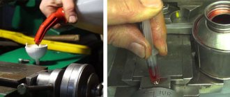
At the first stage, test planing is carried out once to obtain a base surface, which will make it possible to determine deviations along the entire length of the bed. To do this, alternately bring the cutter to the most worn surfaces and remove the metal layer until the wear is eliminated. Finish planing is performed in at least two finishing passes with wide carbide cutters. The last pass is performed with a cutting depth of less than 0.05 mm, constantly wetting the cutter and the surface of the guides with kerosene. When wear exceeds 0.4-0.5 mm, the guides are subjected to rough and fine planing. The main disadvantage of this repair method is the considerable time it takes to dismantle the bed, transport, install the bed on the planer table, align and remove the restored bed.
When cutting the flat prismatic surface of the guides, small metal particles of various sizes and shapes are torn out from the solid frame. Furrows and grooves appear on the surface, forming a rough surface. Therefore, sometimes after machining it is impossible to do without scraping or vibration rolling. This increases the strength of the guides due to plastic deformation (changes in the structure of the material). Vibration rolling achieves smoothing of micro-roughness and irregularities by translational movement along and across the axis with specially treated balls or rollers.
Repairing lathe guides using one of the described methods is an element of complex work related to restoring the full functionality and accuracy of metal-cutting equipment. But we should not forget that the quality of the repair, with a minimum period of time for its completion, significantly depends on the degree of preparation of the machine for repair and the qualifications of the mechanic.
Source
Repairing the caliper carriage
Restoring the accuracy of the lower guides, which are associated with the base guides, without taking into account wear - this is where you need to start repairing the caliper carriage.
Also, when repairing the carriage, it is necessary to restore the perpendicularity of its plane under the apron of the base plane (under the gearbox).
The location of these planes is measured by a level. The thickness of the probe placed under the carriage will determine the level of deviation (value).
The parallelism of the longitudinal guides and their parallelism to the axis of the transverse feed are also subject to restoration.
It should be noted that repairing a caliper carriage is a very labor-intensive process; it is very difficult to do it yourself, so the company must schedule maintenance of the device on a schedule.
The carriage guides can be restored using compensation pads or acrylic plastic.
The cross slide of a screw-cutting lathe can be repaired by grinding. The rotary sled begins by scraping the surfaces, after which they begin sanding.
If necessary, the upper skids are also repaired.
To do this, the surface is scraped, aligned, polished, after which the accuracy of the surfaces’ mating with the guides of the rotary slide must be checked.
See the video for scraping the cross carriage.
Video:
Areas of use of turning equipment
Screw-cutting lathes vary in weight and size, which directly depends on the industry where they are used. They can produce short and long, thin and wide parts. These lathes can cut internal and external threads on parts. The heavier the part, the more massive the machine for processing it.
Light weight turning equipment is used:
- in experimental workshops;
- in instrument making;
- in the manufacture of watch movement parts.
This type may have a mechanical supply of blanks to the cutter, which allows for faster production of identical parts, if necessary, to produce them in small batches. For the production of piece products, this mechanism is not required, which will be reflected in the design of the lathe.
In the industrial production of threaded parts and tools, medium-weight machines are more often used. Their design contains many automatic systems, which, along with rotary mechanical parts, require preventive checks and debugging. Moving, twisting, rotating, cutting and drilling parts require regular lubrication.
Heavy weight turning equipment is used for more repetitive operations. On it are machined:
- shafts;
- turbines;
- wheels for trains.
Despite the small range of products and a small selection of operations, these machines cannot be called simple. There are also many components in its design that require constant care and monitoring. Lubrication and cleaning of parts becomes more difficult due to their heavy weight.
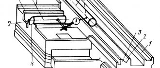
Machining the outer cones with the upper caliper slide rotated
The essence of the method for processing outer cones with the upper slide of the caliper rotated. With this method of processing cones, the rotary slide of the caliper is installed as shown in Fig. 154. In this figure: 1 - the workpiece (its front part is a cone); 2 — upper caliper slide; 3 — handle of the feed screw of this slide; 4 - cutter. By rotating handle 3, we will feed cutter 4, and it will process the conical part of part 1.
Determining the rotation angle of the upper caliper slide. The angle of rotation of the upper slide of the caliper when processing a cone is determined by the following rule.
In order for the inclination angle of the cone being processed to be equal to the required one, it is necessary to install the upper slide of the support at an angle to the center line of the machine equal to the inclination angle of this cone.
Rice. 154. Machining the cone with the upper caliper slide rotated
Counting the rotation angle of the upper caliper slide. The angle of rotation of the upper slide of the caliper is measured according to the divisions marked (Fig. 154) on the supporting flange 5 of its rotating part. Each such division usually corresponds to 1°, so smaller readings (1/2°, 1/4°) have to be done by eye.
Disadvantages of the method of processing the outer cones with the upper caliper slide rotated. The main disadvantage of this method is that processing is usually carried out with manual feed of the cutter, because Only large lathes have automatic feeding of the upper slide of the support. Manual feed is often uneven, resulting in unsatisfactory cleanliness of the machined cone surface. The length of the cone processed by the method under consideration is limited by the largest movement of the upper slide of the support, which even on such a modern machine as 1K62 is only 140 mm. It should be noted, finally, that processing even such relatively short cones with manual feed is tiring for the turner.
Outer cones machined with the upper caliper slide rotated. From the above it follows that the conical surfaces of the part can be processed with the upper slide rotated:
- if the length of the cone generatrix is small;
- if the cone being processed has a large slope angle;
- if high accuracy of the slope angle is not required;
- with low requirements for surface cleanliness.
Checking cones processed with the top slide rotated. The measurement of such cones, mostly short ones, is carried out with goniometers, for example a universal one (Fig. 155, a, b).
Rice. 155. Universal protractor (a, b) and examples of its application (c, d, e)
The main part of the universal protractor is disk 6, which is integral with ruler 9. A scale with degree divisions is applied around the circumference of the disk. The rotary disk 2 can be installed in the required position relative to the disk 6 and secured by means of the head 5. Attached to the rotary disk is a vernier 1, each division of which corresponds to 5 minutes, and a holder 8 of the ruler 4. The ruler can be secured in the required position by the head 7.
Rulers 9 and 4 can be installed in such a position that the angle formed by their working edges will be equal to the required one. The value of this angle is measured using the scale of disk 6 and vernier 1, as in the case of determining the readings of a caliper. Let us assume that after fixing the rotary disk 2, the vernier 1 has taken the position shown in Fig. 1 relative to the scale of disk 6. 155, b. The zero line of the vernier has already passed the 12th line of the scale of disk 6, and the 40th line of the vernier most closely matches one of the scale lines. In Fig. 155, b these strokes are marked with an asterisk. This means that the angle between the working edges of rulers 4 and 9 at their given position is 12° 40′.
Additional ruler 3 is used when measuring acute angles; in this case, whole degrees are counted not from zero, but from the 90th stroke of the scale of disk 6.
In Fig. 155, c shows checking the angle at the apex of the working cone of the center of the lathe with a universal goniometer, and in Fig. 155, d, e - checking the angles of the bevel gear.
Daily care
The most reliable care for a lathe is to prevent damage to it. Preparation for the next work shift should be carried out immediately after finishing work and disconnecting the machine from the power supply. At this stage of maintenance, the following operations are performed:
- Chips and other technical debris are swept away from the surface.
- It is necessary to dissolve oil and dirt with kerosene and wipe dry with a rag.
- To avoid corrosion, all parts that do not have a paint coating are lubricated with oil.
- The oil cans are filled with grease.
Before starting a shift, it is necessary to check the presence of lubricant and inspect the equipment for damage or loose parts. During work, it is necessary to observe safety precautions when working with turning mechanisms - this will minimize injuries in the workplace and reduce the risk of equipment breakdown. During work you must:
- The use of protective screens, which will avoid clogging the lathe with metal shavings and small abrasive particles that arise during processing of the part.
- Timely replacement of drilling and cutting parts.
- Control over the reliability of fastenings of cutters and drills.
- During operation, do not allow the formation of long chips, which, if wound around the rotating parts, can damage the mechanism.
- You can turn on the machine only after the cutter is lowered onto the blank, in the place specified in the drawing.
Video covering basic maintenance principles.
Lathes after major overhaul: restoration and operation
In situations where turning equipment fails, it is not at all necessary to purchase a new expensive unit. After proper repairs, lathes will again be able to efficiently and effectively perform all technological operations for metal processing. Before understanding such a process as repairing a lathe, it is necessary to remember what turning is and how the equipment for its implementation is designed.
It is not always possible to buy new equipment. There is only one way out - repair