Scope of application and benefits
Rotary tables are widely used on machines for various purposes - both on automatic lines for mass production of parts, and in individual installations.
These are milling, vertical drilling machines, forging hammers, presses and other equipment where it is necessary to ensure rapid movement of the workpiece relative to the working body. Rotary tables are also used in welding operations to perform relief and spot welding. The main advantage of a rotary table is the ability to process parts in different planes. Thus, for milling machines, in addition to moving the workpiece in three main directions (longitudinal, transverse and vertical), the rotary table can provide rotation of the part in the vertical and horizontal planes. The table ensures movement of the workpiece in various coordinates, fixing it at the required angle of inclination and performing high-precision processing.
The use of a rotary table can significantly reduce processing time and increase labor productivity. When performing welding operations, this type of equipment allows you to install the part outside the work area, thereby not interrupting the production cycle. The functionality of the equipment is also significantly increased.
Convenient work element
The rotary device is a special housing that is fixed in the working area of the milling machine. After fixing the mechanism, the milled elements begin to move in three directions at once:
If you have to perform multifaceted processing of different parts, then you cannot do without a rotary mechanism, which is characterized by advanced capabilities.
It uses a rotary table, which makes the equipment more functional and productive. If there is a table, the workpiece can rotate around a vertical and horizontal axis .
In turn, the rotating mechanism itself moves in different directions on the machine, setting the desired tilt for the future part. Thus, CNC machines are capable of processing spiral and round workpieces. If we are talking about manually controlled equipment, then the rotary mechanism will perform transitions, rounding workpieces and milling curved surfaces.
Design Features
A coordinate table is a special additional device for a milling or drilling machine, which allows you to move a fixed part along the desired path. Thanks to the convenient design, the labor intensity of the process is reduced and time is saved. The mini-table can be industrial or hand-made. If you know how to work with a welding machine, you can make the device yourself in a private workshop. The advantages of such devices include:
- simplicity of design and ease of use during operation;
- compactness, due to which the machine is not cluttered with equipment;
- saving money in handicraft production.
But a homemade coordinate table allows you to make only small, simple parts. For more professional work, you will need a factory model. Another disadvantage is the relatively rapid wear of the device. In addition, manual manufacturing requires a detailed drawing; the accuracy of assembly and subsequent operational efficiency depend on it.
Features and Specifications
Rotary tables, which are equipped with modern milling machines, are distinguished not only by high functionality, but also by very convenient operation. Thanks to such details in the design of the mechanism, labor productivity increases significantly, while costs are reduced. It is the rotary table that provides the necessary movement of a particular workpiece with which the operator is working in different coordinates. The part can be securely fixed at the desired angle of inclination, which helps to carry out high-precision processing.
Modern models of rotary tables are available for a variety of milling machines. These can be not only sophisticated and expensive CNC machines, but also the simplest and most versatile devices that are often found in home workshops. Thanks to the wide range of milling tables, any craftsman can choose the appropriate option: both a beginner and an experienced professional.
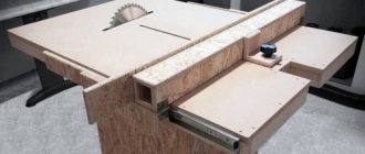
A rotary table for a milling machine significantly simplifies the operator’s interaction with this equipment. The element in question consists of several main components. For example, modern manual rotary devices have the following components:
- reliable stationary support (pipes or adjustable legs can be used);
- table top or base plate of different sizes;
- mounting plate or mounting type plate;
- elevator for a threading machine (can be cam or wedge);
- panel responsible for turning off and starting the device.
The design may also contain auxiliary elements, which make it much easier and more convenient for the operator to work with the equipment. Such elements include:
- rigid vertical stop;
- boards and profile;
- comb type stop;
- horizontal stop installation groove;
- dust collector or dust removal window;
- drawers in which it is convenient to store available tools and supplies.
Today there are many variations of router tables. These can be parts with different functionality, design and technical equipment. The cost of different models also varies greatly.
Types of rotary tables
Rotary tables for metal-cutting machines and other equipment are classified depending on the possible direction of movement. There are five main types of tables:
- Swivel-tilt. It can rotate the workpiece around its own axis and tilt it at an angle from 0 to 90°.
- Rotary with longitudinal movement . Used when milling holes inside flat steel products. There are models equipped with a dividing disk to divide the working area into functional parts.
- Rotary horizontal-vertical tables . Provide the ability to efficiently process workpieces in vertical and horizontal positions. This design is, in particular, widely used in circular milling and helical grooving.
- Horizontal rotary table . Used for circular milling, circular hole drilling and other operations. The simplest and most versatile design option.
- Rotary table with transverse-longitudinal movement . The most technologically advanced design option significantly increases the capabilities of the machine, especially in the absence of its own transverse-longitudinal movement system. The table has the ability to completely rotate along the base, which makes it possible to process parts with a complex configuration, the surfaces of which are located at different angles relative to each other.
Rotary tables are available in standard sizes. Main diameters: 320, 400, 500 and 630 mm.
Modification of rotary systems
PROMA OS-250 25002501 – designed for fixing workpieces in a horizontal position, for drilling holes, cutting threads.
PROMA OS-250 25002501
The equipment also operates in several positions:
- horizontal;
- vertical.
For greater versatility, it should be additionally equipped with a special dividing panel.
Technological characteristics:
- rotation angle – 360 degrees;
- type of hole – MkSh cone;
- T-slot size – 12 mm;
- Warranty period – at least 3 years.
“Anchor” is a universal device; it makes it possible to perform the following operations on a milling machine:
- milling;
- boring;
- gear hobbing;
- marking;
- drilling
Milling machine Anchor
This mechanism can be easily rotated to any desired angle. The device has a special mount for fixing the workpieces being processed.
Fastening also occurs directly on the faceplate, using special tacks and clamps.
Options:
- diameter -100 mm;
- type of hole – cone MT 2;
- T-slot angle is 90 degrees.
Vertex VUT-6, VUT-10, VUT-12 – This tilting mechanism was specially designed as an accessory and is easy to use in a wide variety of machines. On milling equipment, an inclined system of this type helps to carry out several technological operations:
- circular milling;
- processing of holes of different diameters;
- slot milling;
- creating grooves;
- milling of keyways;
- processing the workpiece at a given angle.
Vertex VUT-6
The rotating mechanism on such a machine remains the most important part of the entire equipment. Without it, it is simply impossible to process most complex workpieces.
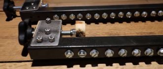
Rotary table design
The figure above shows the simplest version of the rotary table design. A bushing (10) is pressed into the table body (11). The spindle (2) rotates in it. The table faceplate (1) is installed on the spindle. The bushing (7) is also pressed into the body. A rack-type clamp (5) is directed into it, which enters the bushing (3) under the action of a spring (6).
A handle (4) is provided to control the latch. The faceplate is rotated using a rolling bearing consisting of a cage (12), rings (14) and balls (13). To adjust the axial clearance, a nut (8) and a locking screw (9) are used.
What types of rotary mechanisms are there?
It is no secret that modern technologies are developing at a steady pace and this trend is noticeable in all sectors of human activity. The metalworking industry is no exception. A wide range of various accessories and tools allows you to choose the most effective rotary mechanism for your milling machine. By the way, many models have excellent performance and are relatively cheap.
The rotary mechanism, which moves in horizontal and vertical planes, allows for complex milling of circular workpieces, which is necessary for creating helical grooves. also allows you to work with metal components or steel workpieces that have a small angular distance between them. The table allows you to conveniently process parts horizontally and vertically.
The tilting design is also great for milling steel structures that have been fixed at an angle of 0-90 degrees.
This solution will be convenient in cases where there is no need to regularly install or dismantle working parts, since the design of the table surface makes all upcoming procedures difficult. The equipment has special disks capable of dividing the plane into several working zones.
One of them is horizontal. Most often it is present in small-sized universal-type installations, which can carry out a number of milling operations on the machine. Processing of workpieces is carried out at the highest level of all corner elements, grooves and ledges.
In addition, you can also find vacuum tables on the market, which are manufactured in different versions. In this case, the workpiece is pressed onto the turntable using an appropriate mechanism that ideally holds it in the desired direction.
Types of gears for table movement
With a small tabletop machine, the table is moved mechanically. But the greater the speed, accuracy and performance required, the more carefully the type of drive is selected. Electric motors are mainly used.
The essence of the unit’s operation is to convert the rotational work of the engine into translational motion of the table plane. There are three types of transmissions:
- rack and pinion;
- belt;
- ball screw.
The choice of node type is made based on:
- workpiece movement speed;
- machine engine power;
- required processing accuracy.
Machining accuracy at various transfer units
| Type of transmission mechanism | Accuracy Rate |
| Ball screw | 6-12 microns |
| Rack and pinion | up to 10 microns |
| Toothed belt | 50 … 100 µm |
Advantages of Ball Screw:
- possibility of high-precision processing;
- small backlash;
- smooth movement of the table;
- quiet operation;
- ability to take heavy loads.
Ball Screw Drawing
A significant disadvantage is the limited feed speed. The decrease in speed is especially noticeable when the propeller length is more than 1500 mm. Approximate speed calculation: for a 1 kW drive, the rotation speed is 3000 rpm. With a screw pitch of 10 mm, the transmission speed is 0.5 m/sec. In this case, 3 m will be covered in 6 seconds.
Another disadvantage is the high cost. You can reduce the cost of the project by using a connection with a screw and nut. In this case, it is necessary to ensure constant lubrication of the unit.
In new generation drilling machines, lubrication of the movable mechanisms of the coordinate surface is carried out automatically. The device contains sensors for monitoring the temperature of important parts.
The rack and pinion transmission ensures high speed and sufficient accuracy. The disadvantage is the high degree of play when transmitting forces from the drive.
Installing a belt is the most budget-friendly and common method when creating a table with your own hands. The low cost of belt drive and feed speed up to 1 m/s is compensated by the following disadvantages:
- rapid wear;
- loss of tension due to stretching;
- possibility of breakage during acceleration;
- low accuracy of work.
When purchasing a coordinate table for drilling or do-it-yourself installation, you must take into account the working conditions. The ratio of all mechanisms in terms of parameters: workload, service life, heating and cooling will give a good result during operation. This is especially important when making it yourself from scrap materials.
Review and comparison of factory models
| Model | KT70 | KT150 | G-5757 | KRS-475 |
| Table dimensions, mm | 200*70 | 200*200 | 312*140 | 475*155 |
| Longitudinal movement, mm | 134 | 150 | 203 | 330 |
| Transverse movement, mm | 46 | 150 | 125 | 150 |
| Vernier division, mm | 0,05 | 0,05 | 0,02 | 0,02 |
| Weight, kg | 1,14 | 4,9 | 17 | 23,5 |
| Price, rub | 8046 | 16510 | 11900 | 14000 |
KT70 KT150 G-5757 KRS-475 Article rating: (votes: 4 , average rating: 3.00 out of 5) Loading...Share with friends: Similar publications
- Types and varieties of metal cutters for the machine
- Classification of turning cutters for metal: carbide, with replaceable inserts, alloyed
- Technology for sharpening drills of various types
- Metal machines
- Woodworking machines
- Universal machines
- Special machines
- Machine equipment
- Machine Reviews
- Contacts and advertising
Machine Reviews
- Review of the FSSH-1A milling machine: design and technical parameters
View all test reviews
- Milling machine knowledge test
- Lathe knowledge test
- Test for knowledge of industrial machines and accessories for them
Machine passports
All about rotary tables for milling machines
A milling machine is a functional and practical device that is used both in home workshops and in large industries. Such equipment consists of several main components. Tabletop designs may include a rotary table.
Advantages and disadvantages of self-production
A coordinate table is an additional structure to a milling, drilling metal or woodworking machine. Thanks to it, you can increase equipment productivity by reducing the labor intensity of the parts processing process. The workpiece is simply fixed on the working surface and can move smoothly along a given path.
Homemade coordinate tables have the following advantages:
- small dimensions;
- simple design form;
- controlled mechanically;
- used in handicraft production.
Their main advantage is saving money. Making such a design from scratch will cost much less than buying a factory-made manipulator. Of course, there are a number of difficulties when making it yourself. A suitable drawing is needed, according to which the required trajectory of the workpiece will be set. If there is no someone else’s experience, then you will have to create it yourself, but any error when drawing the diagram will make itself felt during work. In addition, a homemade table is only suitable for small-scale production, since the simplest homemade mechanisms wear out much faster than factory ones.
For mass production of parts and their processing, only a factory model of a coordinate table is suitable.
Simple design form
Small dimensions
Mechanical control
Saving money
Types of modifications
To increase the rate of production and its diversity, it is necessary to take care of choosing a suitable model of a rotary structure for retrofitting universal equipment.
It's not just new products on the market. You can also purchase a used rotary table for a milling machine. Rotary mechanisms allow you to move the workpiece in the cutting zone not only in two planes, but also to rotate it. In this way, circular machining or helical groove milling can be performed. The ability to create a slight slope allows you to install the workpiece with small angular values.
The rotation angle along the C coordinate is possible up to 90 degrees. This eliminates the need to reinstall the inclined workpiece. But additional supports somewhat limit the output of the tool.
The dividing table for a milling machine has a special sinus disk, which allows you to divide the working area into several sectors. A crank device allows you to fix the working surface in a given position. For safety, latching elements are provided.
The most popular are rotary tables for CNC machines. A separate drive is provided to control them. This allows parts to be processed in four planes.
To protect the working surface from shocks, deflections, and vibrations, it is covered with a protective layer. For this purpose, plastic or bakelite is used. In addition, the placed panel will protect the cutting tool from breakage in the event of an unexpected contact.
Design selection
When choosing a design, you need to decide on its dimensions. If equipment that processes a part will be installed on a coordinate table, then its dimensions must be taken into account. If it is needed to fix the workpiece, it is mounted on the frame of the drilling equipment, and its width and length will be about 35 x 35 cm.
Tables are also distinguished by the type of fastening:
- When making a coordinate table with your own hands, the structure is equipped with a mechanical fastener. This is the simplest solution in terms of implementation, but it has a number of disadvantages. For example, it often leads to processing errors, and there is a risk of deformation of the product surface.
- Vacuum fastening is considered the best option. With its help, precise positioning of the workpiece on a horizontal plane is ensured. When an air stream is supplied into the gap between the tabletop and the workpiece, the pressure in this area changes. Thanks to this, it is possible to perform processing more efficiently (without mechanical damage to the product).
- Workpiece weight clamping is suitable when using a drill press to machine heavy parts. Due to its mass, the base product remains in the same place even with strong impact.
The functionality of the table depends on the number of degrees of freedom:
- If there is only one, then the workpiece can only be moved in one direction (this is a good option for processing flat products).
- If there are two degrees, it becomes possible to move the workpiece along X and Y coordinates.
- If there are three of them, then the part can move up, down and along the Z coordinate.
If the table is made for home production and processing of parts, then using two degrees of freedom is more than enough.
When making a coordinate table with your own hands, it is important to decide for what purpose it will be used. The parameters of the manipulator are selected in accordance with the dimensions, weight and shape of future workpieces. To work with various parts from metal and wood, a complex multifunctional mechanism is made. Usually, home craftsmen have enough capabilities of a small-sized table with mechanical fasteners and two degrees of freedom.
Mechanical
Vacuum
Fastening under the weight of the workpiece
Materials and tools used
To work you will need a welding machine, a drilling machine, an angle grinder with discs, a hammer, brushes, and a corner. At the preparatory stage, it is necessary to select the material for the base of the device, the control mechanism and guides. The accuracy of the future operation of the device, service life, reliability of the device, and financial costs of manufacturing depend on the correct choice of these components. To create a base, one of three metals is suitable:
- cast iron;
- steel;
- aluminum.
The first material is rarely used in work. The reason lies in its fragility, heavy weight, and fragility. Steel wins by these criteria, which is why it is often used in production. Its only drawback is its high cost. Aluminum is much more affordable. Its advantages are lightness and softness. But it is only suitable for small-sized tables, since the malleable metal cannot withstand large heavy parts.
Step-by-step creation of a wooden table with your own hands, useful tips
When making a coordinate table with your own hands, you need to think about what type of drive the device will have. According to the control method, manipulators are divided into three types: mechanical, electrical, and program control. The latter drive is not used in self-production. The electrical analogue gives a small error, but in private conditions it is problematic to use. For personal home appliances, a more suitable type of control is mechanical. However, it has a drawback - the lack of perfect accuracy.
For manual production, rail or cylindrical guides are suitable.
Cast iron
Steel
Aluminum
Mechanical drive
Electric
Software controlled
Manufacturing instructions
Once the type of material and type of construction have been selected, they proceed directly to work. At the first stage, it is necessary to draw up an accurate drawing indicating the dimensions of all parts. If there is no ready-made scheme, you should develop it yourself. The final result is largely determined by the accuracy of the location of the parts relative to each other. The process of assembling a coordinate table with a mechanical drive consists of the following steps:
- the main assembly is welded from a metal profile 2 mm thick;
- check the geometry of the cross and clean the seams with a grinder;
- a block of guides is assembled on the welded central unit (travel is 94 mm);
- nuts of size M10 are installed inside the profile;
- a handle with a bearing is assembled on a threaded rod (M10);
- weld the base from a corner having a U-shaped configuration;
- screw all parts onto the built-in nuts;
- lubricate moving elements with technical oil;
- install the device on the bed of the milling machine.
The manipulator structure should be assembled on an absolutely flat surface.
Securing workpieces
To secure the workpieces on the working surface of the structure intended for rotating the workpieces, two methods are used.
The first is with standard mounting hardware through T-slots. The second method is to use a vacuum. With vacuum fixing, there are no mechanical devices, which allows processing along the entire perimeter of the workpiece. The pump, pumping out air, imitates the effect of a suction cup. A tabletop with such fixation of parts can be installed on almost any machine. Only an external pump or compressor is required.
Materials and mechanisms of structural elements
The durability of the structure and cost depend on the material of the product. You should immediately decide what type of table it will be - steel, aluminum or cast iron. The second important step is to decide on the control mechanism. You should also decide whether the drive should be mechanical or electric. The third step is to select guides. This will affect the processing accuracy of the workpieces.
Base
The following materials are used for the base:
- Cast iron. Expensive, heavy material turns out to be very fragile in operation, so it is used extremely rarely in the production of a drilling machine.
- Steel. The material is the most highly durable and durable. Its main drawback is the cost. Not every master will be able to purchase it.
- Aluminum. Light and soft material is easier to work with. It is not as expensive as steel. But it is not suitable for making a large-sized table, since it will not withstand the heavy weight of large workpieces. This is an ideal option for creating mini-equipment.
If the master processes metal workpieces, then it is better to make the table from steel or cast iron. True, you should immediately evaluate your costs: perhaps purchasing a ready-made manipulator will cost less than expensive hardware. An aluminum tabletop is suitable for working with wood or plastic.
Cast iron
Steel
Aluminum
Warping characteristics
Coordinate-type tables, which are equipped with drilling machines, can be made with bases made of various materials:
- cast iron;
- become;
- light alloys based on aluminum.
Tables with a base made of aluminum construction are not designed for heavy loads, so they are used to equip drilling machines that process parts made of soft materials (wood, plastic). The advantages of devices whose frame is made of aluminum profile are:
- light weight;
- ease of installation;
- affordable price.
PROXXON-MICROMOT coordinate table made of high-strength aluminum alloy for benchtop drilling machine
Thanks to the simplicity of its design and the availability of manufacturing materials, such a table is easy to make with your own hands. If you don’t want to use a home-made device when working on a machine, you can purchase a ready-made kit for its assembly, which is produced by many companies.
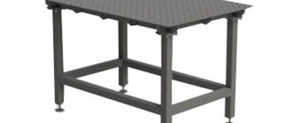
Industrial coordinate tables for drilling machines, which are used most intensively and experience significant loads during operation, are manufactured with bases made of cast iron.
Cast Iron Cross Table for Industrial Drilling Machine
Both serial and home-made coordinate-type tables can be made on the basis of welded steel frames, which demonstrate high reliability. When making such a frame with your own hands, you should keep in mind that welded joints do not withstand vibration loads well, so in the finished structure it is necessary to get rid of internal stresses as much as possible. This is achieved through appropriate heat treatment (tempering).
Coordinate tables, depending on their purpose, can be made according to two design schemes:
- cross;
- portal
Tables made according to the first scheme are equipped with universal drilling machines, on which parts of complex configurations are processed. The design features of such devices allow access to the workpiece being processed from three sides. Portal-type tables are equipped with machines on which holes are drilled in sheet blanks.
Gantry 3-axis CNC table
Drive unit
The drive is a control mechanism with which the coordinate table will change its position. It happens:
- Mechanical. The easiest way is to make it yourself. It allows you to significantly reduce the cost of the table. The basis is a conventional screw or belt drive - this is enough to set up small-scale production. Mechanics are not capable of providing 100% accuracy, and this is its clear drawback.
- Electric. It guarantees zero error when performing work operations, but it is very difficult to do it yourself. Often found in factory models of tables. If there is no own power source near the workplace, this option will not work.
Models with CNC (computer numerical control) should be included in a separate category of coordinate tables. This is high-tech equipment that is used by large enterprises for production in huge volumes. Their main advantages: good performance, as well as complete or partial automation of the process. Disadvantages: high cost, such a drive is not suitable for some parts.
Mechanical
Electric
CNC
Guides
The accuracy of the workpiece processing depends on these elements, so they need to be selected correctly. Among those that you can do with your own hands, the following are distinguished:
- Rail. Rectangular guides are considered structurally more advanced. When using them, lower friction losses are observed and serious errors are avoided. It is possible to connect a lubricant supply system.
- Cylindrical. The use of rounded guides is fraught with high heating due to friction. They are suitable for machines of the so-called small category, but you will have to lubricate all the mechanisms manually.
The guides are made with a carriage and bearing units. The use of plain bearings will ensure high precision machining of the part. The use of a rolling shaft support will reduce friction and extend the service life of the manipulator.
The rolling bearing can cause noticeable play, which reduces the accuracy of the workpiece.
The carriage is a block of guides (mechanism assembly) that moves directly along them. It can provide increased flange dimensions, which allows it to be mounted on the underside of the table. If it is not there at all, then the carriage is placed on top (threaded method).
Rail guides and carriage
Cylindrical
Manufacturing of guides
The accuracy of processing depends on the correct choice of guides. You can make the following designs with your own hands:
- rail;
- cylindrical.
They are created with a carriage and bearing units. You can select guides depending on the type of drive. To achieve the highest processing accuracy, plain bearings are used. When using a rolling bearing, friction is significantly reduced and the service life of the device is increased, but significant play appears, which reduces the accuracy of processing.
Rail design
There are two types of guide carriage:
- with increased flange dimensions, which allows mounting from below the table;
- the design without a flange is attached from above using the threaded method.
Let us note that the homemade version of the guide should be closed using stainless steel. Stainless steel can withstand high humidity for a long time.
Moving device
When choosing a moving device, you should answer a number of questions:
- What should the processing speed be?
- What positioning accuracy is acceptable when performing work operations.
- How productive the equipment will be used.
A belt moving device is most often used in the manufacture of homemade coordinate tables. It is cost-effective, but has a number of disadvantages. The belt wears out quite quickly and can also stretch during use. In addition, due to its slipping, the accuracy of the moving element is reduced.
Ball screw drive is a more durable and reliable option. Despite the small dimensions of the device, it has a good load capacity, and movement is carried out evenly and with great accuracy. Smooth and almost silent running, as well as high quality surface treatment are not all the advantages of ball screws. However, it also has some disadvantages: high cost and limitations in the speed of rotation of the propeller if its length is more than 150 cm.
Rack and pinion devices provide high speed and accuracy of work, withstand heavy loads, are easy to install and are reliable in operation. The error in rack transmission is extremely low. If their size does not fit, then they undergo a fitting operation.
Belting
Ball screw
Rack and pinion
Mechanisms for transmitting motion
On the simplest models of serial drilling machines and on equipment that is made by hand, coordinate tables are installed mainly, which are driven mechanically. If high precision and processing performance are required from a drilling machine, tables driven by electric motors are installed on it.
Three types of gears are used in coordinate table drives:
- based on gears and racks;
- based on belt mechanisms;
- ball screw.
Helical rack and pinion transmission ensures positioning accuracy
The choice of transmission type is influenced by a number of parameters:
- the speed at which the table and the workpiece attached to it must move;
- power of the electric motor used;
- requirements for precision processing of parts.
High precision of movement is ensured by a ball screw drive, which also has a number of other advantages:
- very slight play;
- smooth movement;
- quiet operation;
- resistance to significant loads.
Ball screw in high precision coordinate table
The disadvantages of this type of transmission are the inability to ensure high speed of table movement and the significant cost of such a mechanism.
To reduce the cost of a homemade coordinate table for a drilling machine, you can equip it with a drive based on a conventional screw drive. However, in this case, care must be taken to ensure that the transmission screw mechanism is lubricated as often as possible.
Homemade coordinate table with screw gears and cylindrical guides
A budget option is also to use a drive for moving the coordinate table, made on the basis of a belt drive. When installing such a drive on a home-made coordinate table, you should take into account the disadvantages of using it:
- rapid wear of belts;
- stretching of belts during operation;
- increased risk of belt breakage under increased loads;
- low accuracy.
Accuracy and high speed of movement are ensured by coordinate table drives, made on the basis of a rack and pinion transmission. Meanwhile, when using such a drive, you should be prepared for the fact that play will form in the elements of its mechanism after a certain period of active use.
DIY Turntable for 3D scanning and 360 photo shooting
Hi all!
I have a new version of the PhotoPizza
and I made a video for her showing the assembly process that I wanted to share.
PhotoPizza
is an open project of a rotating object table for photographing objects from all sides (3D photo-360, spin photo).
The platform's control unit is based on Arduino
. You can assemble this device yourself from available components using detailed instructions, and you do not need deep knowledge of electronics. Official project page
The new platform is made of PVC (Polyvinyl chloride) and weighs only 5 kg
At the same time, it can withstand a load of up to
40 kg.
For a load capacity of up to
100 kg,
the platform must be assembled from acrylic.
A very light material and suitable for turntables with a small load capacity (30-50 kg), the load capacity depends on the uniform distribution of the mass of the photographed object along the plane of the rotating disk. If you distribute the weight correctly, you can place an object weighing 60-70 kg. Due to its light weight, the platform is convenient to use for on-site photography, even taking into account transportation using public transport. White material makes it easier to shoot subjects against a white background, but I don't recommend using the standard drive of any streaming platform. The disk wears out and gets dirty, and therefore, it is necessary to place an additional circle of paper on top, or better yet, thin, matte plastic, approximately 0.7 mm thick. Unlike acrylic, PVC material is much softer and can be pressed through after applying a point load, at the same time, it is more popular in the field of outdoor advertising, it costs less and it is easy to find scraps for parts of the turntable.
The new design also provides the possibility of assembly with fixation of the upper disk.
In this non-transparent version of the platform, the upper disk is attached rigidly and cannot be removed without unscrewing the nut of the central axis Material -
PVC 10 mm
Nominal load capacity -
30 kg
Maximum load capacity -
40 kg
Can rotate a person weighing up to
75 kg
, but operation with such a load Not recommended.
Circle diameter - 480 mm
Suitable for photogrammetric 3D scanning of objects - this is a method of constructing a 3D model based on analysis of a sequence of frames from different angles.
Possible shooting speed - 100 frames in 15 seconds
Customizable rotation parameters -
acceleration, rotation speed, endless rotation, rotation by a certain number of steps, 4 customizable programs
Remote control with an IR remote control and buttons at the bottom of the screen Autonomous operation is possible
Use as a hanging system:
Rated load capacity -
5 kg
Maximum load capacity -
10 kg
Weight and physical size:
Weight of the complete set -
5 kg
Height -
Depends on the height of the engine, 70-90 mm
Length, on the engine side -
565 mm
Width -
524 mm
Diameter of the rotating disk -
480 mm
Files for cutting material 2 files, for transparent and opaque plastic, differ by a window for the display in the control unit. Files are presented in *.cdr and *.eps formats
File for Arduino firmware The next version of the firmware will support controlling the camera shutter via IR or wire.
- List of components