Repair by scraping
Scraping of guides or scraping followed by lapping remains the most effective way to restore their geometric and technical accuracy. And now this method is often used, demonstrating excellent results in machine bed repair for many decades. First of all, it is necessary to examine the condition of the guides and determine the degree of their wear. The place where the wear is minimal is taken as the base level, and the measurement data is entered into a table, on the basis of which repairs will be made. In a lathe, the base surface is most often taken to be the location of the tailstock, which practically does not wear out during operation of the equipment. The method includes the following steps:
- installation of the machine bed on a rigid base (repair stand), the longitudinal and transverse position of the bed should be adjusted exactly in the horizontal plane using wedges, shoes or using jacks;
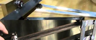
- after completion of the preparatory work, rough (preliminary) scraping is performed with a working scraper width of 20-25 mm, while maintaining a length of strokes on the surface of more than 10 mm and achieving 4-6 spots when checking paint in 25x25 mm squares. This achieves the breakdown of large spots into smaller ones;
- semi-finish scraping is performed with a 12-16 mm scraper, stroke length 5-10 mm until 8-15 spots per square are achieved;
- finishing (finishing) scraping is carried out with a scraper 5-10 mm wide and strokes 3-5 mm long to achieve 20-25 spots per square.
[Show slideshow]
Since the guides of the lathe bed are quite long, processing is carried out along the beacons, dividing the total length into sections. The first beacon is always the place of maximum production. At a distance less than the length of the straight edge from the first beacon, a second beacon is scraped, located in the same plane as the first. Then the entire surface between the beacons is scraped, followed by moving to the adjacent area. Periodically, apply a ruler with paint to assess the condition of the guides and the quality of work.
Watch the video of rough scraping
Non-hardened parts of lathe guides are subjected to this treatment; the method guarantees the achievement of high surface accuracy (0.002 mm per 1000 mm length). The tiny holes formed after scraping are able to hold the lubricant well and distribute it evenly. The quality of scraping depends entirely on the professionalism of the worker.
Lathe bed. Preparation for repair
The quality of a major or medium repair with a minimum completion time depends on the degree of preparation of the machine for repair and the correct organization of the work of a team of mechanics.
Before stopping the machine for repair, its operation is checked at idle speed in order to identify increased noise and vibration at each stage of spindle speed, and the sample is also processed to determine the condition of the spindle rolling bearings. Check the radial and axial runout of the spindle. These checks are mandatory, since this makes it easier to identify defects, which in some cases are very difficult to identify with a disassembled machine.
The results of the checks are taken into account when compiling a list of defects and repairing the machine.
It is not advisable to carry out other tests of the machine for accuracy in accordance with GOST 42-56 (recommended in some literary sources), since the accuracy of the machine assembly is ensured at all stages of the repair process.
This chapter discusses several variants of technological processes that are used for major or medium repairs of body (basic) parts and assemblies of most models of screw-cutting lathes, for example, 1K62, 1601, 1610, 1613D or 250, 1612V, 1615A, TV-320, 1A616, 1E61, etc. correspond to the modern level of repair production and can be used by repair bases with different levels of equipment.
Technical characteristics, photographs and drawings are given on the page Screw-cutting lathe 1K62 .
Lathe bed. Calendar schedule for major repairs
A very important event is the organization of machine repair according to the calendar schedule. The machine repair schedule determines the sequence and timing of repair operations, the completion of components and the final assembly of the machine,
In addition, on the first day, the team washes parts and defects the machine and begins repairing other components of the machine.
Repair by grinding
It is not always possible to use planing or longitudinal milling machines for repairs due to the long length of the lathe bed. In this case, the bed guides are restored using a portable device with a grinding head, which is installed directly on the equipment bed.
Repairs can be made on site, without removing the machine from the foundation. This method ensures high repair accuracy, low surface roughness, and is also indispensable when processing hardened surfaces. This method is many times more productive than scraping, but experts still prefer finishing planing.
[Show slideshow]
Carriage repair and restoration
Due to wear on the carriage guides, the straightness, parallelism and mutual perpendicularity of the surfaces are disrupted, as well as the coaxiality of the holes of the screws and shafts mounted on the table and console relative to the parts moving along them, mounted on the carriage. Therefore, when repairing the guides of cantilever milling machines, the straightness of all guides, including wedge guides 2 and 8, the parallelism of surfaces 1 and 4 to surfaces 5 and 7 (Fig. 69) in directions b-b and c-c, and the mutual perpendicularity of surfaces 3 are restored and 6 in directions a-a and a1-a1.
Restoring the accuracy of guides is usually done by removing a layer of metal until signs of wear are eliminated. However, this causes an even greater misalignment of the holes for the lead screws and shafts in the table, carriage and console.
To establish the alignment of the longitudinal feed screw with the axis of the holes of the mating parts mounted on the carriage, holes for the fastening bolts are milled in the screw brackets and the brackets are aligned. The axis of the cross-feed screw is aligned using the method of marking the blank for the uterine nut “in place” and then the screw is threaded. In some cases, this technique cannot be implemented, and therefore it is necessary to bore holes, install compensating bushings and adjust gears (due to changes in the center distance). This work usually takes a lot of time and is not of sufficient quality. Therefore, it is rational to repair carriage guides by installing linings (wear compensators), while maintaining the original relative position of parts and assemblies.
You should not start repairs from the surfaces of the carriage mating with the console, since this will fix the position of the carriage resulting from uneven wear of the guides. In this case, the restoration of all other surfaces relative to the transverse guides is associated with an unreasonably high labor intensity of repair work.
Repair of carriage guides should begin with the surfaces mating with the longitudinal table. Textolite, nylon, acrylic plastic, cast iron, bronze, etc. are used as lining.
Typical technological processes for restoring guide carriages of milling machines are given in table. 9, 10 and 11.
In table Figure 9 shows the technological process for repairing guide carriages by scraping. This process is mainly used when there is slight wear (less than 0.05 mm) on the guides. The main disadvantage of this method is the high cost of physical labor and the need to subsequently establish the alignment of the lead screws and shafts.
In table 10 shows the most rational way to restore guide carriages - by installing compensation pads. This method is especially effective for repeated repairs, since in this case a significant reduction in labor intensity is achieved (almost half) with a high quality of repair work.
In table 11 shows the technological process for restoring guides with acrylic plastics. This progressive method ensures high quality repairs, while the labor productivity of a repairman increases by 5-6 times compared to manual scraping (see Chapter XIII).
In Fig. 70 shows the method of installing and aligning the carriage on wedges 4 when restoring the guides mating with the surfaces of the table, and in Fig. 71 is an example of installing the carriage on the same wedges and aligning it on the console when restoring the lower guides.
Installing the lead screw and shaft
The procedure for combining the axes of the lead screw and shaft with the feed box and apron of the lathe is well demonstrated by a video of such a process.
This procedure is performed in the following sequence.
- The feed box housing of the lathe is fixed on the bed.
- The longitudinal slides are mounted in the middle of the frame, securing their rear clamping bar with screws.
- The lathe apron is connected to the carriage using screws.
- Test mandrels are inserted into the holes of the apron and feed box, into which the lead screw and shaft enter.
- The carriage with the apron is brought to the feed box and the amount of their misalignment is determined in the contact area of the control mandrels.
- The alignment of the mandrels is achieved by installing new linings, scraping the machine guides or reinstalling the feed box.
I repair the guides of small calipers, milling attachments - geometry correction, finishing scraping. Dimensions - starting from small watchmaking machines such as Boley, Bergeon, Lorch, etc., T-28, schaublin 70, T-65, etc. up to size schaublin 102, C-1, MN-80, TV-16, TSA-16
Repair technology for cylindrical grinding machines
Repair of bed guides
The overhaul process presented in this chapter is typical for various models of cylindrical grinding machines and is designed for repair bases (shops) of medium and large machine-building plants. Using this technology, cylindrical grinding machines of models 3151, 3160A, 3161, 3164, etc. can be repaired. The technological process provides several options for repairing individual assembly units using simplified methods, depending on the specific conditions and state of the repair base. These repair options allow technically poorly equipped repair bases (shops) to carry out high-quality equipment repairs.
High demands are placed on grinding machines performing finishing operations. The accuracy of processing products on these machines mainly depends on the condition of the bed guides, carriages, headstocks and tailstocks, as well as the accuracy of the location of the spindle axes and the condition of their bearings. Therefore, the repair of such machines has certain specifics.
One of the main bases when repairing cylindrical grinding machines is the bed guides. Inaccurate repair of these guides leads to incorrect positioning and interaction of the main assembly units of the machine, which in some cases cannot be corrected even by additional adjustments in place.
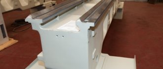
Rice. 6.1. Cylindrical grinding machine bed
When repairing the frame, it is necessary to restore the straightness of all guides, while eliminating the curvature of the surfaces 1—
3 and 6-8 (Fig. 6.1).
Surfaces 2, 3 and 7, 8
of the prismatic guides must be mutually perpendicular, which also needs to be restored. Surfaces 1–3 wear out much more than surfaces 6–3, so the former are repaired by finishing planing, grinding or scraping, and the latter, as a rule, by scraping (Table 6.1). The procedure for repairing the bed by grinding the guides on a longitudinal grinding machine is as follows.
1. Install the bed on the table of the longitudinal grinding machine, checking it to ensure that the guides are parallel to the longitudinal movement of the grinding machine column along the bed. Using an indicator mounted on the body of the grinding headstock, when the column moves, check the parallelism of surfaces 1 and 3.
By moving the grinding headstock along the traverse, check that surfaces 6-8 are parallel to the direction of movement of the headstock. The installation accuracy of the frame according to the indicator is 0.02 mm along the length of the guides.
2. Grind surfaces 1-3 sequentially, achieving the surface roughness parameter R a
= 1.250.63 µm. The straightness tolerance of the guides is 0.02 mm over a length of 1000 mm. Straightness and curvature are checked using a device (see Fig. 2.7).
3. Grind surfaces 6-8 one by one (Fig. 6.1). For technical conditions and testing methods, see table. 6.1 (operation 3).
Typical technological process for repairing bed guides by scraping
Source
Table of contents
Lathes are used to process cylindrical parts. They include many varieties that differ in size and additional functions. Industrial models such as the 16K20 lathe are very common and widely used in modern industry. In order for the device to function normally, you need to know all the features of its parts.
The lathe bed serves to secure almost all mechanisms and components that are used on this equipment. It is often cast from cast iron to create a massive and durable structure that can last a long time. This is due to the fact that it will be subject to heavy loads. You should also not forget about stability, since massive large models use enormous energy during operation and the base must resist the load well.
photo: lathe bed
The machine bed and guides are attached with bolts to the stands or paired legs. If the device is short, then two racks are used. The longer it is, the more racks may be required. Most cabinets have doors, allowing them to be used as drawers. The guides should be treated with great care and avoided from being damaged. It is not advisable to leave tools, workpieces and other products on them. If you still have to place metal objects on them, then you should put a wooden lining before doing this. For better care, before each use of the machine, the frame must be wiped and lubricated. When the work is completed, shavings, dirt and other unnecessary objects should be removed from it.
The design features of the frame of metal-cutting machines may differ depending on the specific model, since they are designed for the convenient and safe placement of all equipment components. But the basic principles remain the same in many cases, so we can look at the basics using popular models as examples.