Guides are an important part in the design of a milling machine. Many craftsmen can make CNC guides with their own hands; most practitioners have experience working at home.
When planning home furniture production, it is necessary to maintain precision in design. Therefore, many masters mastering it need high-quality equipment. A special woodworking mechanism will make work easier and allow you to create high-quality products in a short time.
To ensure that products are highly accurate but meet modern specifications, CNC models are used.
Computer numerical control
Numerical program control provides such an opportunity, but not every entrepreneur can buy it. It is for this reason that there is a need to manufacture a home-made unit, for the construction of which parts of our own production are used.
The main parts of milling machines designed for processing a particular material are guides. They are ball or roller bearings whose purpose is to move the carriage. Their goal is to speed up, simplify and add precision to production.
Stiffness and preload
During operation, profile rail guides are subjected to elastic information due to the applied load. Indications of the amount of deformation depend on the types of rolling elements. But one way or another it becomes smaller when the load increases.
To increase the rigidity of the system, preload is applied. It reduces the life of linear guides by causing internal stress in them, but is capable of absorbing deformation loads when the linear guide is operated under severe vibration or shock loads. Due to the fact that preload causes elastic deformation of bearings, they become dependent on the negative influence of installation errors. This suggests that more attention should be paid to the precision of the mounting surface.
Types of preload:
- normal - used in the presence of minor vibrations;
- light - used in the presence of light vibrations and light torque;
- medium - used for shock loads and strong vibrations, as well as for overturning loads.
Cylindrical shafts
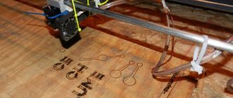
Assembling a laser CNC machine with your own hands,
a cylindrical shaft on the base
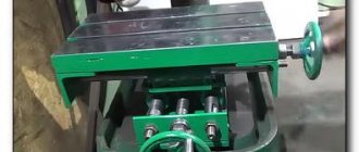
The design of the cylindrical shafts allows you to maintain the level along the entire length, completely eliminating sagging under the weight of the carriage or your own. Such guides are also called linear support shafts; they are fixed directly to the body of the CNC machine through the threaded holes provided in the supports. Large carriages can move along such guides without sagging.
Disadvantages of cylindrical shafts:
- short service life;
- noticeable play in the bushings.
If linear-type bearings work equally well with loads in different directions, then carriages on cylindrical shafts show less stability. This is explained by the closed surface of the bushings, which carriages do not have. Therefore, you should be prepared for the fact that a small CNC machine with a heavy carriage on support shafts will operate with a greater error than the same CNC machine on conventional round rails.
Types of linear bearings on the shaft:
Ball bushings
Linear rolling bearings have larger backlashes compared to rail guide carriages and lower load characteristics.
In addition, to protect the carriage from rotation, it is necessary to use at least two guide shafts per axis. Disadvantages of linear rolling bearings:
Correct installation of rolling and sliding bearings requires preliminary preparation of the workplace, shaft and suitable tools. Depending on the nature and direction of the load in the assembly, the inner ring is tightly fixed onto the shaft, or the outer ring of the bearing is tightly fixed into the seat.
To install bearings without an inner ring, the level of grinding of the raceway on the shaft is checked (at least 46 HRC). The diameter of the shaft seat must be larger than the space through which the bearing passes. With the same shaft diameter along the entire length of the working area, the bearing for installation is heated to +100 degrees in mineral oil, and freely passes to the landing site, where it cools, after which it fits tightly into the working position. It is used for mounting bearings and freezing with dry ice down to -80 degrees, for example, when the diameter of the outer ring and the seat in the body of the part are the same. In general, there are several ways to install bearings :
- fixing / floating;
- at a loss;
- stretched out.
Fixing bearings can also be done in various ways:
- with tension all the way to the shoulder;
- using a spring ring;
- end washer;
- nut;
- conical split bushing.
How to press in a bearing
how to install a bearing ; many car owners independently perform such work using hand tools. However, to replace non-standard bearings on complex production equipment, special equipment is often required: presses, nut-screw pullers, mounting mandrels and cups with rings. When mounting bearings, mandrels prevent misalignment and damage to the bearing. A special press is used to install bearings in removable units, which are subsequently built into the structure of the mechanism. Nut and screw devices are used if there is a thread on the edge of the shaft.
There are general installation rules that must be followed for continued proper operation of the bearings.
- The pressing force is applied only to the ring that fits tightly.
- When pressed simultaneously onto the shaft and into the seat, the force is transmitted to both rings.
- The pressing force is distributed evenly over the entire end part of the ring, for which drifts, cups, mandrels and rings are used. The blows are applied to diametrically opposite sides of the device.
- The rings are not struck directly with a hammer; impact on the rolling elements or cage is not allowed.
- The free ring should not rotate, for which spring preload is used.
How to install bearings without an inner ring
A special installation technique requires the installation of roller bearings without an inner ring and a cage. To fit onto a shaft with a coated raceway, grease is applied to the outer ring, onto which the rollers (needles) are glued. An auxiliary bushing with a diameter 0.2-0.3 mm smaller than the shaft diameter is inserted into the bearing hole. The shaft is pressed tightly against the bushing and together with it is pushed into the bearing.
Homemade CNC machine. Y-axis design.
DIY Valve Guide Replacement Guide
I made a homemade CNC machine from 80x40 profile pipes. The CNC machine diagram was also made by me. You can watch the video on the Zhelezkin channel. This way I achieved greater rigidity of the X portal. The design along the Y axis is not difficult. Because I describe in my article the entire process of assembling the frame. Therefore, everything is clear how to make such a machine literally on your knees. And so the first thing you need to do is cut the CNC profile to size.
Profile for frame
Screw on two cross members (one in the photo to prevent them from leaking after welding), then scald them and unscrew the bolt.
Screwed the crossbars
After the base profile has been scalded, you need to place two 30x30 profiles on top and scald.
upper cross members
After scalding the top profile, I cut a section from the front. (look at the photo below). This is how I installed it entirely so that the profile was welded evenly.
Install profile on top
And after that I try on Portal X on my homemade CNC machine. But before that I install the rails for the CNC. Since I cut out the extra section of the profile. And now nothing interferes.
I cover the holes in the profile with metal and scald them. Because the holes don't look very nice. Once I have completed all the welding, I will sand down all the welds. Because they don't look nice.
Now I will supply bearings for the CNC machine, and a ball screw 1204.
In the photo below you can see under the KP008 bearing (front) I installed a shim. Because it is needed to align the bearings in height. Since the height of the front and rear bearings are different.
I made this lining from 3mm thick duralumin. See photo below.
Bearing lining.
Drawing. View of the bearing
Close-up.
Connection to Portal X
Once the rails are installed, you can install the portal. I connect the ball screw nut body to portal X (the holes on the portal have not yet been drilled) because I will be drilling locally.
The connection point between the ball screw nut housing and portal X.
Connection to portal X. I also provided a drawing of the connecting plate in the article Portal of a CNC machine. (X)
This is what the connecting plate with the portal looks like
Size of the connecting unit with the portal X
After I have completed all the work on connecting the portal, I can move on to other work.
Mounting units for a CNC machine.
In order for the work to be consistent, I move on to the work of attaching the stepper motors
Since this node is important, I made the fastener from 2mm thick steel
Basics for installing stepper motor mounts.
The left and right parts are the same.
I cut two pieces of steel, the size of which is indicated in the drawing at the top. Since both parts are the same, I indicated the size for only one piece. And now I will install a mount for stepper motors on these plates. But you can do without additional transitional fastening. Because I have already made an additional mount for installing the engines, and I will use it. Because it provides the possibility of installing two types of engines. Since in my case two stepper motors are installed on one driver (Nema 17 motors).
I made the transition mount from 3 mm thick duralumin. For the Y axis I made two of these adapter mounts. But you can install the same fasteners on other axles. See photo below text.
Fasteners for steppers on Y Rear part with installed fastening.
Photo mount Nema 17
Mounting the engine on the adapter mount
Now I remove all the parts and paint the frame and those parts that are not painted. Because it will be difficult to paint later. Photo below. Assembling a CNC milling machine.
Painting a CNC machine
After I painted the machine, I started assembling it. In the photo below you can look at my homemade CNC machine.
Pre-assembly.
Legs for the machine.
For the structure, I will use toothpaste lids as legs. But it is quite possible to use other suitable materials.
The legs of the machine are made from toothpaste caps. The upper part of the paste tube is cut off.
Homemade bearing housing without lathe + drawings
Hello, dear readers and DIYers! For the manufacture of many different machines, it is often necessary to securely fix the bearings. In this article, the author of the YouTube channel “Do It Yourself” will tell you how you can make a bearing housing from available materials.
Of course, the proposed method will require welding work, but will allow you to do without the use of a lathe.
Materials. — Steel pipe 2 inches in diameter, strip 25X4 mm — Nuts M6, M8 — Washers M6X1 — Bolts M6X30 — Sandpaper.
Tools used by the author. — Screwdriver, metal drills — Grinder — Cutting and flap cleaning discs — Semi-automatic welding machine — Vise, file, mallet, hammer, core, ruler, square, marker. Manufacturing process. So, the general view of the bearing housing design will look like this.
The author will produce two housings at once, each of which is designed for two 204 bearings. For the main part of the body, you will need to cut two pieces 30 mm long from a steel pipe with an internal diameter of 50 mm.
The master cuts the resulting blanks along the factory weld. It is clearly visible from the inside of the pipe.
At the next stage, both bearings are inserted into the resulting part, and it is pressed in a vice at different angles until the bearings are tightly seated in it.
To make the lugs, a 25-gauge steel strip 4 mm thick is suitable. Parts 30 mm wide are marked on it. The strip is cored and holes with a diameter of 6 mm are drilled.
Next, the master assembles the body structure as follows. In this case, an M8 nut and a pair of washers play the role of linings during the welding stage.
To completely weld the seams, the bearings are removed from the housing. The outer nuts are also welded to the lugs.
All surfaces of the housings, and especially welding seams, are cleaned with a flap grinding disc. The holes for the tightening bolts must be flared with a 6.5 mm drill, giving them an oval shape. This is necessary so that the bolts do not get stuck in them when tightening.
The master made these cases specifically for the bending machine. The pressure shaft bearings will be installed in them. In exactly the same way, you can make housings for bearings of any size; you just need to select a pipe of the appropriate diameter.
Good mood, good health, and interesting ideas to everyone!
The author's video can be found here.
Source
Become the author of the site, publish your own articles, descriptions of homemade products and pay for the text. Read more here.
This difficult installation process
DIY inverter welding machine assembly
It is better to assemble homemade CNC machines, after preparing the components, strictly according to the drawing so that they work. The assembly process using lead screws should be performed in the following sequence:
- a knowledgeable craftsman begins by attaching the first two motors to the body - behind the vertical axis of the equipment. One is responsible for the horizontal movement of the milling head (rail guides), and the second is responsible for movement in the vertical plane;
- a movable portal moving along the X axis carries the milling spindle and support (z axis). The higher the portal is, the larger the workpiece can be processed. But at a high portal, during processing, the resistance to emerging loads decreases;
- For fastening the Z-axis motor and linear guides, front, rear, upper, middle and lower plates are used. Make a cradle for the milling spindle there;
- The drive is assembled from carefully selected nuts and studs. To fix the motor shaft and attach it to the stud, use a rubber winding of a thick electric cable. The fixation may be screws inserted into a nylon sleeve.
Then the assembly of the remaining components and assemblies of the homemade product begins.
Maximum attention to the bed
The necessary rigidity of the machine is provided by the bed. A movable portal, a rail guide system, a motor, a working surface, a Z axis and a spindle are installed on it.
For example, one of the creators of a homemade CNC machine made a supporting frame from Maytec aluminum profile - two parts (section 40x80 mm) and two end plates 10 mm thick from the same material, connecting the elements with aluminum corners. The structure is reinforced; inside the frame there is a frame made of smaller profiles in the shape of a square.
The frame is mounted without the use of welded joints (welded seams are poorly able to withstand vibration loads). It is better to use T-nuts as fastenings. The end plates provide for the installation of a bearing block for mounting the lead screw. You will need a plain bearing and a spindle bearing.
The craftsman determined that the main task of the self-made CNC machine was the production of aluminum parts. Since workpieces with a maximum thickness of 60 mm were suitable for him, he made the portal clearance 125 mm (this is the distance from the upper cross beam to the working surface).
Creating a wood sanding machine
A homemade grinding machine has a drum design , i.e. emery cloth placed on it . It can be produced in the following varieties:
- surface grinding type, providing grinding in only one plane;
- planetary type, capable of processing a part in different directions, creating an even plane on it;
- cylindrical grinding type for processing cylindrical workpieces.
When securing the abrasive cloth, the following recommendations should be taken into account:
- The width of the tape is selected about 20-25 cm.
- The strips are connected end-to-end, without a gap.
- To strengthen the joint seam, a thick tape is placed under it.
- Only high quality glue should be used.
- The shaft for the sanding strip has a side at the edges that protrudes by 2.5-4 mm.
- It is recommended to use thin rubber (for example, a bicycle inner tube) as a backing for the abrasive element.
Options for homemade guides
The guide mechanism for CNC is often based on the use of a chrome-plated metal pipe.
The guide mechanism can be made from a chrome-plated metal pipe
It has a low cost and is easy to process by changing its shape. In addition, there are a number of disadvantages:
- The protective top layer wears off very quickly, then the metal wears out faster.
- When the load on the pipe is high, it does not provide the necessary strength.
This solution is cheap for a specialist, but such a machine will only last for a few tens of hours. This is due to the disadvantages of galvanized or chrome-plated pipes, which themselves are made of soft metal, subject to rapid wear under load. A router used in conjunction with such guides will significantly reduce their service life.
In addition to these methods, milling cutters with low power should be used as moving parts of the device. They give the manufactured parts precise, thorough processing; they are most often used on woodworking machines. They have a low price and short production time.
Main types of guides
In the process of designing and installing machines (factory-made and home-made), different types of guide devices are used. This is due to their purpose - milling, drilling or turning. They can be of two types.
Sliding guides
They are used in low-power equipment that does not require special precision and high productivity. Table-top drilling and turning units and woodworking machines are equipped with such parts.
The polished shaft, as a type of guide, belongs to the budget category. It is the most common.
IMPORTANT! It is made of high-alloy steel, induction hardened and subsequently ground. This treatment increases the operating time, and the shaft wears less.
The polished shaft has disadvantages:
- fastening at the end points, there is no fastening with the frame, which is why there is a lack of rigid connection with the table and the presence of processing errors,
- sagging with increased length, so we allow a maximum of 1 meter. It is recommended to have an optimal ratio of shaft diameter to length (0.06-0.1) in order to achieve normal results.
Mounting surface accuracy
Profile rail guides are installed using fastening on a machined base surface. The fastening method consists of creating a shoulder on the seating surface and placing the base surface or carriage on it. It is possible to avoid distortions if there is a groove in the corner of the bead itself.
There is a direct relationship between rail surface accuracy and moving accuracy. The accuracy of all equipment will depend on this. In this case, the accuracy of the machined mounting surface necessarily corresponds to the specified movement accuracy
It is important to remember that it is necessary to take into account the flatness of the block, while eliminating the deformation of the carriage
Rolling guides
They are designed using rolling bearings.
Linear bearings have more play than the carriage of rail guides; they are less loaded. But it has a number of disadvantages:
- low level of carrying capacity;
- fragility;
- manufacturing with significant play;
- sensitive to the effects of dust and chips on the shaft.
The material for the production of bushings is bronze, brass, caprolon. If tolerances are maintained, bronze plain bearings are as good as rolling bearings. From time to time, if the plain bearing is worn out, it is adjusted to eliminate the gaps. Therefore, the linear bushing is preferred due to its availability and interchangeability.
Shaft and its types
It is worth giving a brief description of the other types.
- The spline shaft is characterized by the presence of a special track for the bushing balls. Characterized by greater rigidity and wear resistance, compared to a conventional shaft, it is suitable for mechanisms in which it is desirable to install guides at the ends. They are used extremely rarely in the design of machine tools due to their high cost.
- The shaft on a support in the form of cylindrical rails of a linear type does not allow sagging under load and its own weight. It is mounted on the frame, securely fixing it. Despite the disadvantages, expressed in the presence of large play in the bushings and their short service life, cylindrical rails have a large load capacity. Different from linear bearings, the carriage reacts differently to the degree of load. A small CNC machine that has a heavy spindle has the potential for reduced accuracy.
- The purpose of profile rail guides is greater accuracy. They are also attached to the frame. Thanks to special raceways, the loads on the carriage are distributed evenly over the surface, and the contact profile of the ball to the rail is an arc. Among the advantages are the presence of good load capacity and wear resistance, and backlash is minimized. The difficulties of producing such rails have a negative impact on pricing; they are expensive. This especially applies to guides supplied by well-known brands whose machines are numerically controlled.
- Roller rails have flat raceways, and in the support module, in place of the balls, rollers are installed that improve all the parameters of the guide. They are used in machines that mill ferrous metals, steel and stone.
- Dovetail is chosen for industrial metalworking equipment if increased fastening rigidity is required. In guides of this type, flat surfaces slide with a maximum contact area. They are made in the form of a monolith with a frame. Due to the complexity and labor-intensive manufacturing and repair process, these guides are therefore not accepted by the hobby machine tool industry.
CNC machines from furniture rods
An excellent option when you need to achieve thorough processing, especially in woodworking machines for the production of furniture in small batches, in belt sanding machines, milling machines based on a ready-made low-power milling machine. Furniture parts are inexpensive, although they have a shorter service life than similar sliding elements from printers or typewriters.
An example of using furniture rods on a format boring machine is shown in the photo. It is clear that the dimensions of the bed and movable table are adjusted depending on the purpose. However, if you use ball-type furniture on a drilling machine, there will be no demolition, since the load and frequency of work on a router or drilling machine are significantly different from the loads on a format-cutting machine.
There is always a way out, and based on the examples given, it is quite possible to select sliding guides for your CNC machine with the desired parameters. Good luck with your work!
Installation of rail guides
It is important to know that linear rail guides are subject to force and torque. For them, the following values must be determined: permissible static moment and load capacity, which are calculated using the formulas
When calculating the nominal life of ball and roller guides, it is necessary to use different formulas.
With a constant stroke length and frequency of movements, the service life is expressed in terms of time. With compact mounting dimensions, profile rail guides have a high load capacity. Installed in various types of machines or other equipment, they are mounted in two different ways: as a horizontal rail and as a side mounting method.
Since the set consists of two parallel rails, the first rail is located on the base side, and the other on the adjustable side.
When working with large shock loads and vibrations, installing additional side parts - a side pressure plate, set tension screws, a conical wedge - helps eliminate them.
Installation of additional clamping parts when working with low loads and low speeds of movement is not necessary.
Homemade guides: instructions
Homemade guides for a woodworking CNC machine of your own making can have several options.
The first implementation option is simple; while executing the unit using this algorithm, it is necessary to assemble a structure consisting of the following parts:
- Bearings - take the counteracting force of the motor.
- Metal corner - acts as a carriage.
- Bolts and nuts - the size must correspond to the inner diameter of the bearing.
Manufacturing instructions:
- First, measure the required length of the metal corner, remove the excess;
- drill symmetrically on both sides, holes of the required diameter;
- Secure the bearings using nuts and bolts.
The design of the guides is ready, it does not require a lot of effort and is quite understandable for an inexperienced craftsman.
Guides made from furniture rods are used in the manufacture of custom-made furniture; to achieve accuracy, a ready-made milling base from furniture parts is suitable. Using polished cylindrical rods in the design.
Experts recommend additionally using bronze bushings, then their size must be equal to the diameter of the guides.
Using old Yantar typewriters, it’s easy to make CNC guides yourself. Their peculiarity is that the moving parts are made in the shape of a corner. You will need the following details:
- moving part;
- separator - a plate in which balls are mounted;
- rails;
- metal plate;
- angles whose length is equal to the rail.
We connect all the parts in the necessary way and get the finished result.
To come in
Already registered? Sign in here.
There are currently 0 users on the page
There are no users viewing this page.
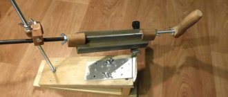
If you're annoyed by chips and sloppy cuts, you'll love the results you can achieve with a sled that doubles as a chip guard. With their help, it is possible to increase the accuracy of the portable saw machine. They will replace the wobbling cross fence and reduce the formation of chips at the edges of the cut. The sled can also be modified for use with a full saw machine.
First, cut out the base of the slide from hardboard 6 mm thick. Then saw both edges of the 40mm thick block at right angles to a final width of 75mm and cut two 610mm long pieces from it. Using glue and screws, fasten the scraps together to form an L-shaped stop. Then glue the stop to the base.
Homemade guides: instructions
Self-made guides for self-made CNC can have several options.
The first implementation option is simple; while executing the unit using this algorithm, it is necessary to assemble a structure consisting of the following parts:
- Bearings - take the counteracting force of the motor.
- Metal corner - acts as a carriage.
- Bolts and nuts - the size must correspond to the inner diameter of the bearing.
Manufacturing instructions:
- First, measure the required length of the metal corner, remove the excess;
- drill symmetrically on both sides, holes of the required diameter;
- Secure the bearings using nuts and bolts.
The design of the guides is ready, it does not require a lot of effort and is quite understandable for an inexperienced craftsman.
Guides made from furniture rods are used in the manufacture of custom-made furniture; to achieve accuracy, a ready-made milling base from furniture parts is suitable. Using polished cylindrical rods in the design.
Using old Yantar typewriters, it’s easy to make CNC guides yourself. Their peculiarity is that the moving parts are made in the shape of a corner. You will need the following details:
- moving part;
- separator - a plate in which balls are mounted;
- rails;
- metal plate;
- angles whose length is equal to the rail.
We connect all the parts in the necessary way and get the finished result.
For a small home CNC machine, you should use car racks as guides.
Car racks are suitable for small CNC machine
They are used in domestic cars, so getting them is not difficult. Rods from racks are used, they are durable and made of high-quality metal.
Therefore, having shown ingenuity and imagination, the master’s possibilities become limitless. With a little thought, it is not difficult to assemble a CNC machine with your own hands from scrap parts that are available and not used for their intended purpose. This will reduce the cost of home production and increase its productivity and quality.
The mechanics of each machine, regardless of its purpose and type, contains components that are considered basic. Therefore, it is unacceptable to ignore their parameters
It is generally accepted that guides are considered such an important component for metal-cutting or woodworking devices. They will determine error-free and cyclical work
Therefore, anyone who decides to create a machine must ensure that its design uses high-quality CNC guides, which have a positive effect on the functionality of the device. They don’t skimp on purchasing components.
Case types
There is a certain classification of bearing housings. Each type differs in its purpose, mounting method, configuration and size. The following varieties are standard today:
- stationary solid;
- stationary detachable;
- flanged.
The one-piece stationary type of case is made of pure nickel, which makes it more rigid and simpler. The axial fit of bearings in the housing has a complex axial type of installation. Therefore, this variety is used in low-speed mechanisms that have a small shaft diameter.
The detachable stationary housing is made of gray cast iron. It consists of a lid and a base. These body elements are connected with bolts. This design makes it easy to change the bearing when it wears out, make a secondary bore of the liner, and also adjust the gap. This is a common type of housing in mechanical engineering.
Read also: How to quickly charge a car battery
The flanged body is similar to the previous type. It consists of a base and a cover connected by bolts. It is used for very demanding parts. It serves as a support for both the end and through shafts.
Which designs to choose?
Not everyone can afford to purchase, say, a CNC machining center for the production of small-scale parts at home, a format-type machine or for turning. But a homemade CNC unit, made with your own hands, is real. The assembled device in capable hands will demonstrate examples of correct processing of parts.
When assembling the mechanics of programmable machines, homemade linear guides are usually used, since there is no need for devices with circular motion
Let us pay attention to some of the designs used in this case.
Galvanized or chrome-plated pipes
They come with different diameters and can be used as rods when installing low-power devices - surface grinders, drilling or lathes. The bronze bushing moves along a polished cylindrical rod. Sometimes a support is made without it. Pipes have low prices and are easy to process. Although there is a minus: a short resource (the protective layer wears off after 15-20 penetrations, after which the steel wears out more intensively); there is no required level of strength under high loads.
Fraser
An effective router is one in which the guide mechanism is made from a used dot-matrix printer or Yantar typewriter. With this option it will last a long time. There is no need to look for very wide bearings; their internal diameter should be equal to the diameter of the bolts.
Furniture rods
The problem of mechanics for CNC machines can be solved properly with the help of furniture rods. Moreover, homemade products using them guarantee thorough processing on woodworking, belt sanding equipment, and even a low-power milling machine. Furniture components are cheap, although they have a short resource.
Polished shaft
Inexpensive and frequently used type of guide. The essence of the treatment is to inductively harden the top layer, which helps to increase the service life and reduce the intensity of the wear process. The shaft is then polished and the carriage moves with minimal friction.
Homemade
It is often practiced to install homemade guides using what is available. For example, you can use angle steel, bearings, nuts and bolts.
IMPORTANT! Do not take aluminum, in this case you need to be prepared to frequently replace the part. The tracks in it are eaten away by the ball bearings of the carriage
It is better to give preference to a steel corner. If the mechanism is expected to be used intensively, it is better to harden and polish it to reduce friction on the bearings.
Stocks
When assembling a small home machine, they sometimes use car strut rods from a domestic car as guides. They are durable and made of high quality metal. This will significantly reduce the cost of components.
There is also this option: aluminum busbars from the switchgear of a transformer substation with pressed-in copper-graphite bushings from a MAZ starter. And the moving units are made from pneumatic valves, which are used to control pneumatic cylinders.
When making guides and carriages for CNC with your own hands (roller or ball), you must use the following expected criteria:
- saving specified parameters;
- smooth linear movement of carriages;
- efficiency;
- low friction.
NOTE! Some craftsmen advise doing without bushings in machine mechanics. This option is possible, but it is fraught with deterioration of the manufactured products, and the service life of the installed rod device will be reduced
Linear Motion Modules
Recently, in connection with the development of automation, the use of linear motion modules, which consist of:
- durable supporting profile;
- precise guiding system;
- durable drive mechanism;
- Servomotor with easy control.
In such a modular component, guides with both ball bearings and roller bearings are used. The working drive is carried out using a linear motor, toothed belt or ball screw mechanism.
Linear tables have also found their application, used when it is necessary to move large masses along axes. Due to their dimensions, they absorb large moment loads. Linear tables use:
- linear motion bushings;
- guides with ball circulation.
Types of linear guides
Linear guides come in two types:
- with ball circulation;
- with circulation of rollers.
Ball guides are made in two, four and six rows. They are miniature, suitable for use in limited installation space. Linear guides are manufactured with different drives. Among them, the most common are a toothed belt or a ball screw drive (ball screw drive).
Roller guides are made in the form of cylindrical guides and guides with a flat cage.
All guides must have the following main properties:
- low friction;
- high efficiency;
- smooth linear movement;
- ability to maintain operating parameters.
Welcome to the website of an open project to develop a CNC machine based on Arduino with your own hands
The project Simple CNC machine on Arduino was conceived for the development, debugging and testing of software necessary for the operation of machines with computer numerical control (CNC).
Accordingly, I wanted to spend a minimum of money on the manufacture of the mechanical and electronic components of the machine.
The Arduino board was chosen as the controller due to its enormous capabilities for interacting with various devices. The functionality of Arduino is easily expandable due to the ability to connect a huge number of devices that support standard data transfer and control protocols. The official website arduino.cc contains comprehensive information about connecting devices to Arduino, as well as programming Arduino.
CNC milling machines, or rather programs for CNC machines, work with vector images, which in themselves are quite expensive. This initially shifted the direction of research to the development of a CNC milling machine that works with free raster images (regular files in bmp, jpg, gif format, etc.). Putting everything together we get absolutely amazing characteristics:
- low cost of a CNC machine (less than $100 or 6,000 rubles excluding the cost of a computer);
- easy accessibility of all machine parts;
- working with raster images that anyone can easily create in a simple graphics editor (for example Paint);
- extensible platform for the development of many related systems;
- Ideally, the software should be able to process photographs and/or images obtained from a conventional scanner.
Initially, it was planned to use a CNC machine on Arduino for milling flat figures, ornaments and three-dimensional bodies. However, a contact sensor was subsequently connected to the machine for 3D scanning. Then, a laser module for engraving/burning was installed on the machine. And finally, the CNC machine was turned into a 3D printer: this required installing an additional unit called an extruder.
Thus, we get not just a 3-axis CNC milling machine on Arduino, but a whole platform on the basis of which it can be easily assembled:
- machine for milling 2D shapes and 3D bodies;
- contact 3D scanner;
- CNC laser engraver/burner;
- 3D printer.
The site contains detailed assembly diagrams of a CNC machine, including its modifications, drawings of a CNC machine, software source codes, as well as firmware source codes for Arduino.
A CNC machine on Arduino and its modifications were assembled by hand. For industrial purposes, such a machine with CNC is certainly not suitable, but it is suitable for piece production and mastering the principles of operation of mechanics and software.
In addition, the site has a separate section dedicated to purchasing components of a homemade CNC machine and the necessary consumables, which describes where, how and at what price you can purchase the required components of a simple CNC machine.
Shelves for tools and materials
Setting up a home workshop begins with installing practical shelves for tools with your own hands. They can be made of metal or wood, or have a combined design - a metal frame with shelves made of wood, plywood, chipboard, plastic, etc.
The following basic structures :
- Racks in the form of a frame and shelves located at different heights.
- Shelves mounted on the wall. They can be installed on brackets or attached with dowels directly to the wall surface.
- Hanging shelves with ceiling mounting.
Recommendation . Shelf-boards are convenient and practical in the home workshop . They can be used to install small tools that can be viewed and easily removed.
Practical shelf-boards have this design. The basis is a shield cut from plywood 8-12 mm thick.
There are 3 types of fasteners mounted on it:
- a rail with slots for placing tools with a handle in a vertical position (hammer, screwdrivers, chisels, etc.);
- shelves with a side for placing boxes with small tools (drills, taps, dies, etc.);
- hooks for hanging small tools (knife, scissors, measuring tool, etc.).
This shelf-shield is fixed to the wall using dowels.
Guides for CNC machine
CNC machining centers for small-scale and home use are an expensive thing and not everyone can afford to buy a format boring or CNC lathe, but you can easily make a device with your own hands that is decent in terms of processing quality and cleanliness of the cut. Let's look at several designs, but first we'll look at the factory-made parts to understand the basic principles of operation.
All guides for programmable machines are of circular motion or linear type, this depends on the trajectory along which the moving unit moves in coordinates. We will consider only linear ones, as they are the most popular among DIYers, and there is no particular need for the use of circular devices.
What types of guides are there?
Any machine is based on the precision of processing, which is provided by guide rods. You have to make working units with your own hands, but there are some that you can’t make yourself; only factory-made parts are suitable.
For example, it is unlikely that it will be possible to manufacture the working part of a milling machine, just like with a drilling or turning machine. Therefore, you have to use ready-made solutions - drills, drives, engravers or electric jigsaws. With guides, the situation is simpler, since their characteristics and appearance directly depend on the purpose of the unit.
Almost all of them, used in factory and home-made structures, are of only two types - sliding and rolling. According to the principle of bearings, their method of operation is clear - some are based on sliding, others use rolling bearings in their design.
For low-power equipment that does not require precision and performance, the sliding principle is used. Basically, such parts are used by desktop drilling and turning units, as well as woodworking units. There are also subspecies, but let’s look at those that are easiest to make with your own hands from what is on sale.
Do-it-yourself production of guides for CNC
Guides are an important part in the design of a milling machine. Many craftsmen can make CNC guides with their own hands; most practitioners have experience working at home.
When planning home furniture production, it is necessary to maintain precision in design. Therefore, many masters mastering it need high-quality equipment. A special woodworking mechanism will make work easier and allow you to create high-quality products in a short time.
To ensure that products are highly accurate but meet modern specifications, CNC models are used.
Computer numerical control
Numerical program control provides such an opportunity, but not every entrepreneur can buy it. It is for this reason that there is a need to manufacture a home-made unit, for the construction of which parts of our own production are used.
The main parts of milling machines designed for processing a particular material are guides. They are ball or roller bearings whose purpose is to move the carriage. Their goal is to speed up, simplify and add precision to production.
The accuracy of the machine is the task of the guide rods. They are divided into two types:
The first type is used on machines of low power and not requiring high productivity. These include woodworking, turning, drilling and benchtop machines.
Homemade guides for a CNC machine are made using a linear method; they can be roller or ball. Regardless of the type, they must have the following characteristics: