Introduction
On sale, there are a large number of cheap sensors - rangefinders, including ultrasonic and infrared. All of these devices work well, but due to their significant weight, they are not suitable for flying robots. A miniature robotic helicopter, for example, can carry about 100 g of payload. This makes it possible to use machine vision to find obstacles and avoid collisions with them, using webcams (or other miniature, wireless cameras connected to a computer via USB). Better yet, install two cameras, which will provide the robot with stereo vision, thus, thanks to information about the depth of the image, it will improve obstacle avoidance. The disadvantage of this idea is the relatively large weight of the camera.
Laser rangefinder from webcam
1.1. Principle of operation
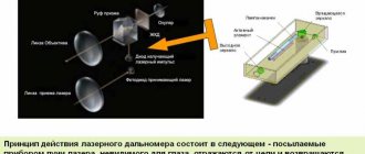
The laser point is projected onto a possible obstacle in the camera's field of view; the distance to this obstacle can be easily calculated. The mathematics here is very simple; data processing is best done in computer applications. (see Fig. 1.1)
Figure 1.1 – Operating principle of the rangefinder
So here's how it works. A laser beam is projected onto an object in the camera's field of view. This beam must be perfectly parallel to the camera's optical axis. The laser dot is captured along with the rest of the scene. A simple algorithm looks for bright pixels in an image. Assuming that the laser point is bright in a darker environment (I used a regular dollar store laser pointer), the position of the point in the frame is initially unknown. We then need to calculate the distance to the object based on where along the Y axis the laser dot is, the closer it is to the center of the image, the further away the object is.
As we can see from the figure above, the distance (D) can be calculated using the formula:
Of course, to solve this equation, you must know h is the fixed distance between the laser pointer and the camera. The denominator is calculated as follows:
To calibrate the system, we will collect a series of measurements where we know the distance to the target, as well as the number of pixels in the center of the image to the laser point.
Using the following equation, we can calculate the angle of inclination as a function of the value of h, as well as the actual distance to each point.
Now we have the calculated values, we can come up with relationships that allow us to calculate the range, knowing the number of pixels from the center of the image. You can use a linear relationship.
Knowing the calibration data, you can calculate:
1.2. Components
To assemble the rangefinder, not many parts are required: a webcam and a laser pointer. To connect the laser pointer and camera, you need to cut a frame from tin or plywood:
The assembled rangefinder should look something like this:
1.3. Software
The handler program is written in two languages: Visual C++ and Visual Basic. You might think that a Visual Basic program is simpler than a VC++ program in terms of code, but there is a trade-off in everything. VC++ code can be built for free (provided you have Visual Studio), while VB code requires the purchase of third-party software packages (in addition to Visual Studio).
Codes for programs written in Visual Basic and Visual C++ can be found at the link: www.cxem.net
1.4. Further work
One specific improvement that could be made to this rangefinder is the projection of a horizontal laser line instead of a dot. This way, we can calculate the distance to the target for each row of pixels in the image [1].
Homemade phase laser rangefinder
In this article I will talk about how I made a laser rangefinder and the principle of its operation. Let me note right away that the design is a mock-up and cannot be used for practical use. It was done only to make sure that it was realistic to assemble the phase rangefinder yourself.
Theory
One often comes across the opinion that with the help of a laser, distance is measured only by directly measuring the time of “flight” of the laser pulse from the laser to the reflecting object and back.
In fact, this method (called pulse or time-of-flight, TOF) is used mainly in cases where the distances to the desired object are quite large (>100m). Since the speed of light is very high, it is quite difficult to accurately measure the time of flight of light, and therefore the distance, in one laser pulse. Light travels 1 meter in approximately 3.3 ns, so the accuracy of time measurement should be nanosecond, although the accuracy of distance measurement will still be tens of centimeters. To measure time intervals with such accuracy, FPGAs and specialized microcircuits are used. However, there are other laser methods for changing distance, one of them is phase. In this method, unlike the previous one, the laser operates continuously, but its radiation is amplitude modulated by a signal of a certain frequency (usually frequencies less than 500 MHz). I note that the laser wavelength remains unchanged (it is in the range of 500 - 1100 nm). The radiation reflected from the object is received by the photodetector, and its phase is compared with the phase of the reference signal - from the laser. The presence of a delay in wave propagation creates a phase shift, which is measured by a range finder. The distance is determined by the formula: Where c is the speed of light, f is the laser modulation frequency, phi is the phase shift. This formula is only valid if the distance to the object is less than half the wavelength of the modulating signal, which is equal to c/2f. If the modulation frequency is 10 MHz, then the measured distance can reach up to 15 meters, and when the distance changes from 0 to 15 meters, the phase difference will change from 0 to 360 degrees. A change in the phase shift by 1 degree in this case corresponds to a movement of the object by approximately 4 cm. When this distance is exceeded, ambiguity arises - it is impossible to determine how many wave periods fit within the measured distance. To resolve the ambiguity, the laser modulation frequency is switched, after which the resulting system of equations is solved. The simplest case is to use two frequencies, at a low frequency they approximately determine the distance to an object (but the maximum distance is still limited), at a high frequency they determine the distance with the required accuracy - with the same accuracy of measuring the phase shift, when using a high frequency the accuracy of measuring the distance will be noticeably higher. Since there are relatively simple ways to measure phase shift with high accuracy, the accuracy of distance measurement in such rangefinders can reach up to 0.5 mm. It is the phase principle that is used in rangefinders that require high measurement accuracy - geodetic rangefinders, laser roulettes, scanning rangefinders mounted on robots. However, the method also has disadvantages - the radiation power of a continuously operating laser is noticeably lower than that of a pulsed laser, which does not allow the use of phase range finders to measure long distances. In addition, measuring the phase with the required accuracy can take a certain time, which limits the performance of the device.
The most important process in such a rangefinder is the measurement of the phase difference of the signals, which determines the accuracy of the distance measurement. There are various ways to measure phase difference, both analogue and digital. Analog ones are much simpler, digital ones provide greater accuracy. At the same time, it is more difficult to measure the phase difference of high-frequency signals using digital methods - the time delay between signals is measured in nanoseconds (this delay occurs in the same way as in a pulse range finder).
In order to simplify the task, heterodyne signal conversion is used - signals from the photodetector and laser are separately mixed with a signal of a similar frequency, which is generated by an additional generator - a local oscillator. The frequencies of the modulating signal and the local oscillator differ by kilohertz or units of megahertz. Difference frequency signals are separated from the received signals using a low-pass filter.
An example of a block diagram of a rangefinder with a local oscillator. M is the laser modulation signal generator, G is the local oscillator.
The phase difference between the signals does not change in this conversion. After this, it is much easier to measure the phase difference of the received low-frequency signals using digital methods - you can easily digitize the signals with a low-speed ADC, or measure the delay between signals (as the frequency decreases, it increases noticeably) using a counter. Both methods are fairly easy to implement on a microcontroller.
There is another way to measure phase differences - digital synchronous detection. If the frequency of the modulating signal is not very high (less than 15 MHz), then such a signal can be digitized by a high-speed ADC synchronized with the laser modulation signal. From Kotelnikov’s theorem it follows that the sampling frequency should be twice as high as the laser modulation frequency. However, since a narrow-band signal is digitized (except for the modulation frequency, there are no other signals at the ADC input), it is possible to use the subsampling method, thanks to which the ADC sampling frequency can be significantly reduced - to several megahertz. It is clear that the analog part of the rangefinder is simplified. This method is discussed in more detail (with all the necessary formulas) here (in English) and here (in Russian). The first article points out that if the signal sampling frequency (fsp) is related to the modulation frequency (fo) by the following relationship: where p is an integer, then the phase calculation process is greatly simplified. It is enough to take N samples of the signal X , after which the phase difference can be calculated using the following formulas: I note that both of the above methods are often used together - low-frequency signals are fed directly to the ADC, high-frequency signals are transferred to the lower frequency region due to heterodyne conversion, and are also fed to ADC.
It was the second version of the phase meter, using a modulation frequency of 10 MHz, that I decided to implement in my rangefinder prototype.
Practice
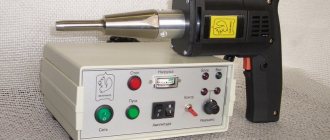
Block diagram of my rangefinder:
In fact, the entire design consists of 3 parts - a development board with a microcontroller, a laser signal amplifier with the laser itself, and a photodetector with an amplifier and filter. In the theory described above, it was assumed that the laser radiation is modulated by a sinusoidal signal. It is not easy to generate such a signal with a frequency of 10 MHz using a controller, so in my design I feed a square wave with a frequency of 10 MHz to the laser. After amplifying the signal from the photodetector, excess harmonics are cut off from the received signal by a bandpass LC filter tuned to a frequency of 10 MHz, resulting in a signal very close to a sinusoidal one at the filter output.
Diagram of the analog part (laser amplifier and receiving part):
The circuit was taken from the Ronja laser communication project, description in Russian. This project implements data transmission at a speed of 10Mbit, which corresponds to the selected modulation frequency. As can be seen from the diagram, the power amplifier for a laser is the simplest, assembled on a 74HC04 chip (contains 6 inverters). Turning on the microcircuit is not entirely correct, but it works. The current through the laser is limited by resistors (also not the best solution). The 5V supply voltage for the amplifier is taken from the debug board. To ensure that the signal from the amplifier is not induced to the rest of the circuit, the amplifier body is made of metal and all wires are shielded. The laser itself (red) is taken from a DVD burner, its power can be set quite high, and it is guaranteed to operate at a frequency of 10 MHz.
The receiver consists of a photodiode and an amplifier assembled on a field-effect transistor and a high-speed amplifier microcircuit. Since the illumination of the photodiode decreases greatly with increasing distance, the gain should be quite large (in this circuit it is approximately equal to 4000). In addition, as the frequency increases, the signal at the output of the photodiode drops noticeably (its capacitance affects). I note that the amplifier in this design is the most important and most capricious part. As it turns out, its gain is clearly not enough. Initially, I assumed that the gain could be changed (in order to attenuate the signal when its value is too large), the circuit used allows this to be done by changing the voltage at the second gate of the transistor. However, it turned out that when the gain changes, the phase shift introduced by the amplifier changes quite significantly, which worsens the accuracy of distance measurement, so we had to set the gain to maximum, applying a 3V voltage from the battery to the transistor gate. The receiver requires 12V voltage to operate, so you have to use a separate power supply to power it. The amplifier is very sensitive to external noise, so it must also be shielded. I took a finished housing from a non-working optical sensor and placed the amplifier in it (the white strip is foil for additional shielding of the photodiode): I note that the aiming of the signal from the laser to the receiver quite significantly degrades the accuracy of measuring the phase difference, so you need to control that such aiming was absent.
The LC filter used in the rangefinder is taken from the receiver. Since the filter cuts off the DC component of the signal, and the ADC does not perceive negative signals, it has to be added using a resistor divider R15, R16. The DC voltage supplied to the divider is taken from the debug board (VCC).
Development board - STM32F4-DISCOVERY. I chose it because to generate two sufficiently different frequencies, a generator of a sufficiently high frequency is needed (PLL STM32F4 can produce frequencies greater than 100 MHz). In the formula relating the modulation and sampling frequencies, I took the coefficient “p” to be 6, so that with a modulation frequency of 10 MHz, the sampling frequency should be 1.6 MHz.
To generate a frequency of 10 MHz, a TIM2 timer is used, operating in the PWM signal generation mode. With a system frequency of 160 MHz, its period is 16 “ticks”. The ADC receives trigger requests from the TIM8 timer. To generate a frequency of 1.6 MHz, its period is 100 “ticks”. All data from the ADC is saved using DMA into an array, the size of which must be equal to two to the power of N. Both timers, ADC and DMA, start once when turned on and are never turned off again. Thus, since the timers are clocked from one source, and four data samples correspond to one period of the measured signal, it turns out that the array will always contain an integer number of signal periods. Since it is not desirable to stop DMA (this simplifies the control of data capture), an interrupt is generated when the first half of the array is full. Having detected that half of the array is full, the controller copies its contents to another array (in order to simplify the program, the second half of the main array is not used). After this, the received data is processed - the average amplitude and phase of the signal are calculated, and the phase shift is converted into distance. The obtained values are displayed on the LCD indicator from the cash register, also connected to the debug board.
The rangefinder must know where the reference point is. To calibrate it, when turned on, an object is placed at the “zero” distance from the rangefinder, after which you need to press a button on the debugging board, and the measured range value is recorded in memory, after which this value will be subtracted from the range measured by the rangefinder.
As I noted above, it was not possible to implement automatic gain control. In this case, a change in the amplitude of the received signal leads to a change in phase shifts in the amplifier, and therefore to additional errors. Therefore, I had to regulate the illumination of the photodiode using a mechanical shutter, rotated by a servo drive - if the illumination is too high, the shutter blocks the light flow. The PWM signal for controlling the drive is generated by the TIM3 timer.
About optics. Without it, a rangefinder is impossible. Its design is clearly visible in the photographs below. The laser is located inside a plastic tube mounted vertically. A small sleeve with a mirror prism is inserted into it. The sleeve can be rotated, raised and lowered, thus moving the laser beam. Since I guessed that the gain would not be enough, I used a large Fresnel lens to receive the signal. Since the laser, lens and photodiode are installed coaxially, at close distances the laser blocks its own beam from the photodiode. To compensate for this effect, I installed a second lens (a magnifying glass with a frame), although the effect is not completely eliminated, so the maximum signal is observed at a distance of approximately 50-70 cm from the laser.
And here are photographs of the resulting structure:
On the indicator, the first number is the amplitude in ADC units, the second number is the distance in centimeters from the edge of the board.
Video of the rangefinder in action:
The operating range of the resulting rangefinder was quite small: 1.5-2 m, depending on the reflectance of the object. In order to increase the range, you can use a special reflector to which the laser beam will need to be directed. For experiments, I made a lens reflector, consisting of a lens with matte paper at its focus. This design reflects light to the same point from which it was released, however, the diameter of the beam increases. Reflector photo:
Reflector usage:
As you can see, the distance to the reflector is 6.4 meters (in reality it was about 6.3). In this case, the signal increases so much that it has to be attenuated by directing the laser beam to the edge of the reflector.
The accuracy of the resulting rangefinder is 1-2 centimeters, which corresponds to the accuracy of measuring phase shifts - 0.2-0.5 degrees. At the same time, to achieve such accuracy, the data have to be averaged for too long - one measurement takes 0.5 seconds. This may be due to the use of PLL for signal generation - it has quite a lot of jitter. Although I believe that for a homemade prototype, the analog part of which is made rather clumsily, and which contains quite long wires, even such accuracy is quite good. I note that I could not find on the Internet a single existing phase rangefinder project (at least with a design diagram), which was the reason for writing this article.
Controller program: link
Laser rangefinder from a web camera
On sale, there are a large number of cheap sensors - rangefinders, including ultrasonic and infrared. All these devices work well, but due to their significant weight, they are not suitable for flying robots. A miniature robotic helicopter, for example, can carry about 100g of payload. This makes it possible to use machine vision to find obstacles and avoid collisions with them, using webcams (or other miniature, wireless cameras connected to a computer via USB). Better yet, install two cameras, which will provide the robot with stereo vision, thus, thanks to information about the depth of the image, it will improve obstacle avoidance. The downside to this idea is the added weight of a second camera.
This article describes how a small laser pointer, coupled with a single web camera, can provide mono machine vision with a wide range of information.
This project is based on an article found here.
Principle of operation
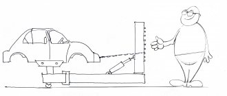
See the picture below. The laser point is projected onto a possible obstacle in the camera's field of view; the distance to this obstacle can be easily calculated. The mathematics here is very simple; data processing is best done in computer applications.
So here's how it works. A laser beam is projected onto an object in the camera's field of view. This beam must be perfectly parallel to the camera's optical axis. The laser dot is captured along with the rest of the scene. A simple algorithm looks for bright pixels in an image. Assuming that the laser point is bright in a darker environment (I used a regular dollar store laser pointer), the position of the point in the frame is initially unknown. We then need to calculate the distance to the object based on where along the Y axis the laser dot is, the closer it is to the center of the image, the further away the object is.
Homemade scanning laser rangefinder
In this article I will talk about how I made a homemade laser scanning rangefinder using the triangulation principle of distance measurement, and about the experience of using it on a robot.
Why do you need a scanning rangefinder?
To date, there are not many methods for indoor navigation in robotics. Determining the robot's position in space using a laser scanner is one of them. An important advantage of this method is that it does not require the installation of any beacons indoors. Unlike systems that use image recognition from cameras, processing data from a rangefinder is not so resource-intensive. But there is also a drawback - the complexity, and accordingly, the price of the rangefinder. Traditionally, robotics uses laser scanners that use the phase or time-of-flight principle to measure the distance to objects. The implementation of these principles requires rather complex circuitry and expensive parts, although the characteristics are decent - using these principles, you can achieve high scanning speed and a long distance measurement range. But such scanners are not suitable for home experiments in robotics - their prices start at $1,000. Rangefinders that use the triangulation principle of distance measurement come to the rescue. This type of rangefinder first appeared in Neato robotic vacuum cleaners:
Quite quickly, amateurs deciphered the protocol of this rangefinder and began to use it in their projects. The rangefinders themselves appeared on ebay as spare parts in small quantities at a price of about $100. A few years later, the Chinese company was able to release the RPLIDAR scanning rangefinder, which was supplied as a full-fledged device, and not a spare part. Only the price of these rangefinders turned out to be quite high - $400.
Homemade rangefinder
As soon as I learned about Neato rangefinders, I wanted to build one myself. In the end, I succeeded, and I described the assembly process on the Roboforum. First version of the rangefinder:
Later, I made another version of the rangefinder, more suitable for use on a real robot, but I was not completely satisfied with its quality of work. The time has come for the third version of the rangefinder, and it is this that will be described below.
Scanning triangulation laser rangefinder device
The principle of measuring the distance to an object is based on measuring the angle between the laser beam hitting the object and the rangefinder lens. Knowing the laser-lens distance (h) and the measured angle, you can calculate the distance to the object - the smaller the angle, the greater the distance. The principle is well illustrated by a picture from the article:
Thus, the key optical components of such a rangefinder are a laser, a lens and a photodetector array. Since the rangefinder is scanning, all these parts, as well as the control electronics, are installed on a rotating head. Here the question may arise: why do you need to rotate the optics and electronics, since you can install a rotating mirror? The problem is that the accuracy of the rangefinder depends on the distance between the lens and the laser (base distance), so it must be quite large. Accordingly, for circular scanning you will need a mirror with a diameter larger than the base distance. A rangefinder with such a mirror turns out to be quite bulky. The scanning head of the rangefinder is mounted on a fixed base using a bearing. The motor that rotates the head is attached to it. The rangefinder must also include an encoder designed to obtain information about the position of the head. As you can see, the Neato, RPLIDAR and my homemade rangefinders are made exactly according to this scheme.
The most difficult thing about a homemade rangefinder is making the mechanical part. It was her work that caused me the most criticism in the early versions of the rangefinder. The difficulty lies in the manufacture of the scanning head, which must be firmly fixed to the bearing, rotate without beating, and at the same time it must somehow transmit electrical signals. In the second version of the rangefinder, I solved the first two problems by using parts of an old HDD - the disk itself was used as the base of the scanning head, and the motor on which it was mounted already contained high-quality bearings. At the same time, a third problem arose - electrical lines could only be routed through a small hole in the engine axis. I managed to make a homemade brush assembly on line 3, fixed in this hole, but the resulting design was noisy and unreliable. At the same time, another problem arose - there was no line to forward the encoder signal, and the encoder sensor in this design must be installed on the head, and the encoder disk with marks must be installed on a fixed base. The encoder disk was not rigid, and this often caused problems. Photo of the second version of the rangefinder:
Another drawback of the resulting rangefinder is the low scanning speed and a strong drop in accuracy at distances greater than 3m. It is these shortcomings that I decided to eliminate in the third version of the rangefinder.
Electronics
In principle, the electronic part of a triangulation rangefinder is quite simple and contains only two key components - a photosensitive ruler and a microcontroller. If there are no problems with choosing a controller, then with the ruler everything is much more complicated. The photosensitive ruler used in such a rangefinder must simultaneously have a sufficiently high light sensitivity, allow the signal to be read at high speed, and have small dimensions. The various CCD rulers used in household scanners are usually quite long. The rulers used in barcode scanners are also not the shortest or fastest. In the first and second versions of the rangefinder, I used the TSL1401 line and its analog iC-LF1401. These rulers fit well, are cheap, but only contain 128 pixels. This is not enough to accurately measure distances up to 3 meters, and is saved only by the possibility of sub-pixel image analysis. In the third version of the rangefinder, I decided to use the ELIS-1024 line:
However, buying it turned out to be difficult. Major electronics suppliers simply do not have these lines. The first line I was able to buy on Taobao turned out to be non-functional. I bought the second one on Aliexpress (for $18), it turned out to be working. Both rulers looked soldered - both had tinned contacts and, judging by the markings, were manufactured in 2007. Moreover, even in the photographs most Chinese sellers have exactly the same lines. It appears that the truly new ELIS-1024 line can only be purchased directly from the manufacturer. The ELIS-1024 photosensitive line, as the name suggests, contains 1024 pixels. It has an analog output and is quite easy to control. The DLIS-2K line has even better characteristics. With similar dimensions, it contains 2048 pixels and has a digital output. As far as I know, this is what is used in the Neato rangefinder, and possibly in the RPLIDAR. However, it is very difficult to find it on the open market; even in Chinese stores it does not appear often and is expensive - more than $50.
Since I decided to use a ruler with an analog signal output, the rangefinder microcontroller must contain a fairly fast ADC. Therefore, I decided to use a series of controllers - STM32F303, which, at a relatively low cost, have several fast ADCs that can operate simultaneously. As a result, I got the following diagram:
The signal from the line (pin 10) has a fairly high level of DC component, and it has to be filtered using an isolation capacitor. Next, the signal needs to be amplified—for this, the AD8061 operational amplifier is used. Objects located far away give a rather weak signal, so I had to set the gain to 100. As it turned out as a result of experiments, even in the absence of a signal, for some reason a voltage of about 1.5V is constantly present at the output of the selected op-amp, which interferes with the processing of results and worsens accuracy of signal amplitude measurement. In order to get rid of this offset, I had to apply additional voltage to the inverting input of the op-amp. 3D render of a routed printed circuit board:
The board was designed to be double-sided; it is quite difficult to make such a board at home with high quality, so I ordered the boards to be made in China (I had to order 10 pieces at once):
For this rangefinder I used a cheap lens with an M12 thread that has a focal length of 16mm. The lens is mounted on the printed circuit board using a ready-made lens holder (these are used in various cameras). The laser in this rangefinder is an infrared (780 nm) laser module with a power of 3.5 mW. Initially, I assumed that the laser radiation would need to be modulated, but later it turned out that with the ruler used there was no point in this, and therefore now the laser is constantly on. To test the functionality of the electronics, the following design was assembled, simulating the scanning head of a rangefinder:
Already in this form it was possible to check what accuracy of distance measurement the rangefinder can provide. To analyze the signal generated by the ruler, test programs were written for the microcontroller and PC. An example of the type of signal from a ruler (an object at a distance of 3 m).
Initially, the scheme was not exactly the same as shown above. During the experiments, I had to partially redo the original circuit, so, as can be seen from the photographs, some parts had to be mounted using wall mounting.
Mechanical part
After the electronics were debugged, it was time to make the mechanical part. This time I did not bother with the mechanics from the HDD, and decided to make mechanical parts from liquid plastic poured into a silicone mold. This technology is described in detail on the Internet, including on Giktimes. After I made the parts, it became clear that it would be easier to make the parts on a 3D printer, they could come out harder, and perhaps it would be possible to make one part instead of two. I don’t have access to a 3D printer, so I would have to order the production of the part from some company. Photo of one of the parts of the rangefinder scanning head:
This part is the base of the head. It consists of a sleeve, onto which a bearing is later placed, and a disk. The disk is intended for fastening the second part of the tower; in addition, the encoder disk is glued to it from below. The sleeve and disk contain a through hole into which a purchased 6-line brush assembly is inserted - it can be seen in the photo. It is those wires that are visible in the photograph that can rotate relative to the body of this unit. To improve operating stability, 2 pairs of brush lines are used to transmit GND and UART TX signals. The remaining 2 lines are used to transmit power supply voltage and encoder signal.
Silicone mold for casting this part:
The second part of the scanning head was made in the same way. It is designed to attach the printed circuit board and laser to the disk. Unfortunately, I don’t have any photographs of the manufacture of this part, so it can only be seen as part of the rangefinder.
A ball bearing is used to attach the scanning head to the base of the rangefinder. I used a cheap Chinese 6806ZZ bearing. To be honest, I didn’t like the quality of the bearing - the axis of its inner bushing could deviate relative to the outer axis by a small angle, which is why the rangefinder head also tilts a little. The attachment of the bearing to the part with the disk and the base will be shown below.
I made the base from transparent plexiglass 5 mm thick. Attached to the base is a bearing, an encoder sensor, a rangefinder motor and a small circuit board. The base itself is installed on any suitable surface using racks. This is what the base of the rangefinder looks like from below:
The printed circuit board contains an adjustable linear voltage regulator to power the motor, and pads for connecting the brush assembly wires. The power supply for the rangefinder is also supplied here. As in other rangefinders, the motor rotates the scanning head using a belt. To prevent it from falling off the bushing, there is a special recess on it. As can be seen from the photo, the bearing is secured to the base with three screws. On the scanning head, the bearing is held by a protrusion on the bushing and is pressed against it by other screws, which simultaneously hold the brush assembly.
The encoder consists of a paper disk with printed marks and an optocoupler with a phototransistor that operates in reflection. The optocoupler is fixed using a stand on the base so that the disk plane is next to it:
The signal from the optocoupler is transmitted through the brushes to the input of the microcontroller comparator. The microcontroller's DAC serves as a reference voltage source for the comparator. In order for the rangefinder to determine the position of the zero angle, a long mark is applied to the encoder disk, marking the zero position of the head (it is visible on the right in the photo above).
This is what the assembled rangefinder looks like:
View from above:
The connector on the back of the rangefinder is used for flashing the microcontroller. To balance the scanning head, a large nut is installed on its front - it almost completely eliminates vibration when the head rotates.
The assembled rangefinder needs to be adjusted - set the laser in such a position that the light reflected from the objects hits the photodetecting line. Both plastic parts contain coaxial holes located under the laser groove. Adjustment screws are screwed into the holes, resting against the laser body. By turning these screws, you can change the tilt of the laser. By observing the shape and amplitude of the received signal in a computer program and changing the tilt of the laser, you need to achieve the maximum amplitude of the signal. Also, triangulation rangefinders require calibration, as I wrote about earlier:
In order to be able to measure distance using a sensor, it must be calibrated, i.e. determine the law relating the result returned by the sensor and the actual distance. The calibration process itself is a series of measurements, as a result of which a set of distances from the sensor to some object is formed, and the corresponding results.
In this case, calibration was a series of measurements of distances to various objects with a homemade rangefinder and a laser tape measure, after which a regression analysis was performed using the resulting pairs of measurements and a mathematical expression was compiled.
The resulting rangefinder has a significant drawback - due to the lack of modulation of the laser radiation, it does not work correctly in any strong illumination. Normal room lighting (even when using a powerful chandelier) does not affect the operation of the rangefinder, but the rangefinder does not measure the distance to surfaces directly illuminated by the Sun. To solve this problem, the rangefinder must include an interference filter that transmits light radiation only of a certain wavelength - in this case, 780 nm.
The evolution of homemade rangefinders:
Overall dimensions of the resulting rangefinder: Base size: 88×110 mm. Overall height of the rangefinder: 65 mm (can be reduced to 55 by reducing the height of the stands). Scanning head diameter: 80 mm (same as a mini-CD disk).
Like any other triangulation rangefinder, the distance accuracy of this rangefinder decreases sharply as the distance increases. When measuring the distance to an object with a reflection coefficient of about 0.7, I got approximately the following accuracy characteristics:
| Distance | Scatter |
| 1m | |
| 2 m | 2 cm |
| 5 m | 7 cm |
Rangefinder manufacturing cost:
| DIY, $ | Wholesale, $ | |
| Base | ||
| Base plate | 1,00 | 0,50 |
| Engine | 0,00 | 1,00 |
| Bearing | 1,50 | 1,00 |
| Brush unit | 7,50 | 5,00 |
| Fasteners | 0,00 | 2,00 |
| Scanning head | ||
| Controller STM32F303CBT6 | 5,00 | 4,00 |
| Photodetecting ruler | 18,00 | 12,00 |
| Other electronics | 4,00 | 3,00 |
| Pay | 1,50 | 0,50 |
| Lens | 2,00 | 1,50 |
| Lens holder | 1,00 | 0,50 |
| Laser | 1,00 | 0,80 |
| Plastic parts | 3,00 | 2,00 |
| Fasteners | 0,00 | 1,00 |
| Assembly | 0,00 | 20,00 |
| Total: | 45,50 | 54,80 |
In the first column - how much the rangefinder cost me, in the second - how much it could cost in industrial production (the estimate is very rough).
Rangefinder software
Before writing a program, you need to calculate the clock frequency at which the photodetector array will operate. In older versions of the rangefinder, the scanning frequency was limited to 3 Hz; in the new rangefinder, I decided to make it higher - 6Hz (this was taken into account when choosing a ruler). The rangefinder takes 360 measurements per rotation, so at this speed it should be able to make 2160 measurements per second, meaning one measurement should take less than 460 µs. Each measurement consists of two stages - exposure (accumulation of light by a ruler) and reading data from the ruler. The faster the signal is read, the longer the exposure time can be, and therefore the greater the signal amplitude. At a line clock frequency of 8 MHz, the reading time of 1024 pixels will be 128 μs, at 6 MHz - 170 μs.
With a clock frequency of the STM32F303 series microcontroller of 72 MHz, the maximum ADC sampling frequency is 6 MSPS (with a conversion width of 10 bits). Since I wanted to test the operation of the rangefinder at a linear clock frequency of 8 MHz, I decided to use the ADC operating mode, in which two ADCs operate simultaneously (Dual ADC mode - Interleaved mode). In this mode, a signal from an external start source triggers ADC1, and then, after a configurable time, ADC2:
As can be seen from the diagram, the total sampling frequency of the ADC is twice as high as the trigger frequency (in this case, the signal from the TIM1 timer). In this case, TIM1 must also generate a clock signal for the photodetector line, synchronous with the ADC samples. To receive two signals from one timer with frequencies that differ by a factor of two, you can switch one of the timer channels to the TIM_OCMode_Toggle mode, and the second channel should generate a regular PWM signal.
Block diagram of the rangefinder program:
The key part of the program is precisely capturing data from the ruler and managing it. As can be seen from the diagram, this process occurs at the hardware level, due to the joint work of TIM1, ADC1/2 and DMA. To ensure that the exposure time of the ruler is constant, a TIM17 timer operating in Single Pulse mode is used.
The TIM3 timer generates interrupts when the comparator connected to the encoder is triggered. Due to this, the rotation period of the rangefinder scanning head and its position are calculated. Based on the obtained rotation period, the period of the TIM16 timer is calculated so that it generates interruptions when the head is rotated by 1 degree. It is these interruptions that serve to trigger the exposure of the ruler.
After the DMA transfers all 1024 values captured by the ADC to the controller memory, the program begins analyzing this data: first, the position of the maximum signal is searched with pixel accuracy, then, using the center of gravity search algorithm, with a higher accuracy (0.1 pixel ). The resulting value is stored in the results array. After the scanning head makes a full revolution, at the moment of passing zero, this array is transmitted to the UART module using another DMA channel.
Using the rangefinder
The quality of operation of this rangefinder, like previous ones, was checked using a self-written program. Below is an example of an image generated by this program as a result of the rangefinder operation: However, the rangefinder was not made to just lie on the table - it was installed on an old Roomba 400 vacuum cleaner instead of the rangefinder of the second version:
The robot is also equipped with an Orange Pi PC computer, designed to control the robot and communicate with it. As it turned out, due to the large voltage drop on the linear power supply of the rangefinder motor, the rangefinder requires a supply voltage of 6V to operate at a speed of 6 rps. Therefore, Orange Pi and the rangefinder are powered by separate DC-DC converters.
I use ROS to control the robot and analyze data from the rangefinder. Data from the rangefinder is processed by a special ROS driver (based on the Neato rangefinder driver), which receives data from the rangefinder via UART, converts it into distances to objects (using calibration data) and publishes it in the standard ROS format. This is what the received information looks like in rviz (ROS data visualization program), the robot is installed on the floor:
The side length of the cage is 1 meter.
Once the data has entered ROS, it can be processed using ready-made software packages. In order to build the apartment map, I used hector_slam. For reference: SLAM is a method of simultaneously constructing a map of the area and determining the position of the robot on it. An example of the resulting apartment map (the shape is somewhat unusual, because the rangefinder “sees” furniture, not walls, and not all rooms are shown):
ROS allows you to combine several programs (“nodes” in ROS terminology) running on different computers into a single system. Thanks to this, only the Roomba and rangefinder ROS drivers can be run on the Orange Pi, and data analysis and robot control can be carried out from another computer. At the same time, experiments have shown that hector_slam also works normally on Orange Pi, loading the processor acceptably, so it is quite possible to organize the robot’s fully autonomous operation.
The SLAM system, thanks to data from the rangefinder, allows the robot to determine its position in space. Using data on the robot’s position and the constructed map, it is possible to organize a navigation system that allows you to “direct” the robot to a specified point on the map. ROS contains a software package to solve this problem, but, unfortunately, I was never able to get it to work well.
Video of the rangefinder in action:
More detailed video of map construction using hector_slam:
Controller program source codes
A simple rangefinder on Arduino
Good afternoon, DIY lovers! Today we will build a simple rangefinder using Arduino Pro Mini. The device is capable of measuring distances from 2 to 400 cm. The error of this device reaches only +/- 1-5 cm, depending on the distance being measured.
Tools and materials
-Arduino Pro mini -Sensor hc-04 -Indicator on tm1637 -Wires (I have MGTF 0.12) -Programmer -Plastic case -Li-on battery -Small switch -Charging board on TP4056 -Superglue -Soldering iron -Solder -Rosin -Drill, drill bits, etc.
Step one. Diagram:
According to the scheme, everything is simple, without additions.
Step two. Preparing the body:
First, we try on the sensor and use a 15 mm drill to drill two holes.
Step three. Firmware:
The sketch highlights variables that you can adjust for yourself. All code is commented out.
Next, we connect the programmer and flash the MK.
Step four. Assembly:
Since the device runs on a battery, we don’t need any extra charge. Therefore, on the Arduino board we solder the LEDs and the reset button (to reduce the size).
Step five. Test:
Note: The fourth segment will always display 0. This is to ensure that the last segment is not empty. It turns out that if the reading is 270, then this means that the distance is 27 cm.
Homemade rangefinder with your own hands
Good day, readers! I'm sure I'm not the only one wondering about purchasing, or better yet creating, a fairly accurate rangefinder with my own hands, with the ability to measure distances of at least several kilometers. A long time ago I became acquainted with interesting material, thanks to which I learned to approximately measure distances using the “thousandths” method. When using this method, as you know, you need to know the dimensions of the remote object. Those who have encountered this know that in the mountains it is difficult to find an object with familiar dimensions. Therefore, I also wanted to have another method that did not require prerequisites. Yesterday, I accidentally came across the design of a homemade optical rangefinder on the Internet. Next is a little copy-paste: “It is difficult to determine the distance by eye. More or less a person copes with this task on level ground. If there is a ravine or river between the object and the observer, then you can make a mistake two to three times.
A mirror rangefinder will help you accurately estimate the distance to various objects.
Make blanks from 33 mm plywood, thin planks or other rigid sheet material, connect them with wood glue into a longitudinal case, leaving the top cover 4 open. End walls 5 are made after the gutter from parts 1, 2 and 3 has already been glued together. Then At the top of the box, attach mirror strips measuring 25x50 mm, as shown in the figure. Glue mirror A tightly with BF-2 glue to the block connecting parts 2 and 5, and mirror B to the flat of the rotating axis. Insert this axis with the lower end into the hole of part 3, cover the case with lid 4 so that the upper end of the axis falls into the hole of part 4. Place an arrow-pointer (made of tin or aluminum) on the upper end of the axis, lubricating the joint with BF-2 glue, and strengthen the protective clamp.
The next stage of work is graduation. Using a measuring tape or ruler, measure 50 m from some vertical object, such as a telegraph pole, and stand in this place. Slowly turning mirror B, align the images of the lower and upper parts of the pillar. Mark the position of the arrow on the scale and write against this mark: “50 m”. Then measure 100 m from the pillar, again combine the images of the “halves” of the pillar, mark the position of the arrow with a mark, writing against it: “100 m” - etc. After calibrating the distance between the marks, divide by eye into smaller parts.
The accuracy of the rangefinder also depends on the length of the arrow: the longer it is, the greater the distance its end travels (at the same angle of rotation of mirror B). But you shouldn’t make the arrow particularly long - this reduces the interval of measured distances. To prevent dust from getting inside the device, insert pieces of glass, thin plexiglass or transparent celluloid into the three holes.
Paint the finished device with nitro or oil paint in a protective color.”
I also read in other articles that instead of mirrors you can use laser pointers, a small magnifying device (some kind of mini monocle). I want to know if anyone has come across such a device? If yes, what subtleties are there in the design? What suitable parts can be made from? Recommended length of the device for more accurate measurements and over long distances. And in general, I will be glad to hear any thoughts about the rangefinder - this and others in general. Thank you!
Source
Laser rangefinder
There are many ways to measure distances - in steps, with a ruler, with a tape measure, etc. The 20th century added a device such as a laser rangefinder to measuring instruments. It is widely used by the military and surveyors for surveying terrain. A laser rangefinder was used to measure the distance to the earth's satellite, the Moon.
Nowadays, rangefinders and levels that use lasers in their work can be found in any construction team involved in the construction of buildings and interior decoration.
Principle of operation
Laser measuring instruments use two principles in their work - pulse and phase.
The first rangefinder consists of two components - a laser and a detector. By measuring the time it takes the laser beam to travel along the path from the source to the reflecting object, you can calculate the exact distance between them. These devices are used to work over long distances. The operating technology is as follows: the laser generates a powerful pulse and turns off. This property allows it to be used covertly. This property is the decisive factor determining the use of this device by the military.
The second type, phase, works according to the following principle. The laser turns on for a while and directs the beam to a distant object, it (the beam) has a different simulated frequency and the distance to the object is calculated from the phase change. Phase measuring distances do not have instruments for measuring the reflected signal. These devices are effective at distances of up to 1 kilometer and therefore are used for domestic needs or as sighting devices for small arms.
Scheme of operation of a laser rangefinder
A laser rangefinder, used in everyday life and in construction, is essentially a mixture of a calculator and a tape measure. Meanwhile, such a device has a number of undeniable advantages:
- This device provides the ability to measure linear dimensions (length, height, width), while the built-in calculator will automatically calculate the perimeter. In addition, the calculating device will help determine the volume of the room;
- The rangefinder is equipped with the ability to store received data in internal memory. They can be used to carry out calculations;
- The device allows you to measure distances at remote distances with someone’s help; by the way, measurements can be taken both in indoor and outdoor areas, in different weather conditions.
How does a laser rangefinder work?
The method for accurate non-contact determination of distance with data output to the display is a complex electronic circuit. The design is based on an emitter, a receiver, a time measurement unit and a microprocessor, the combination of which allows us to fully operate the laser rangefinder. The design of the device, in a more detailed analysis of processor boards and modules, has a decent network, whose structure lies far beyond the understanding of the average person. Even radio amateurs who are interested in electronics assemble rangefinders from ready-made elements using soldering and programming.
Essentially speaking, the operating principle of a laser rangefinder is based on the speed of light and the time it takes for the beam to travel to the surface and back. The laser released from the emitter is reflected from the first solid object that comes across the path (even with a large refraction angle), and partially returns to the device, where it is recognized by the receiving module and records the time it takes to cover this distance. Since light travels at a speed of 299,792,458 meters per second or 29.2 centimeters per microsecond (µs), knowing the time it takes to travel, you can easily calculate the length of the path it travels. Thus, the basic formula used by rangefinders is as follows.
The principle presented above applies to pulse rangefinders, which have the widest possible presence on the construction tools market. These devices have decent accuracy with an error of 0.5 to 3 mm, depending on the built-in signal reception sensor, whose processing speed should be lightning fast.
In addition to the pulse method, there is also a phase measurement method, still based on a laser, but radically different in the method of obtaining information. This principle is based on the frequency of the emitted laser, which does not exceed 450 MHz (on average from 10 to 150). Instead of time, the phase difference (outgoing and receiving) is determined here, on the basis of which the distance to the object is calculated. A phase rangefinder takes longer to obtain a value, but the measurement accuracy is superior to a pulse rangefinder.
Peculiarities
When working with a laser rangefinder, it is advisable to take into account some features of working with this device.
Rangefinders have the ability to take measurements at different distances and with a certain error. Thus, the maximum distance can range from 60 to 200 meters, with an error of 5 cm. These data are indicated in the product passport. Most rangefinder models operate within the range from – 10 to + 50 degrees.
When operating the device outdoors, you must remember that weather conditions play an important role. Performance may be reduced in both poor and sunny weather.
DIY Ultrasonic Rangefinder - Assembly Kit.
Good day to all! I present to you a review of another DIY kit from China. this time we are assembling a rangefinder, the measurement range is from 25 to 400 cm. The kit arrives in a small package, inside there are instructions (though mostly in Chinese), surprisingly even with a diagram and a small handful of parts.
Instructions
The board that is to be soldered is not poorly made, but the component values are not labeled, so without instructions with a sign that corresponds to the ratings, it will be a bit difficult.
Briefly about the element base.
Controller STC11F02, CD4069 inverter assembly.
CX20106A, judging by the description from those that I could find, is a preamplifier for the receiver of IR signals from remote controls. Nearby is a resistor assembly.
Set of capacitors, 12 MHz crystal and 8550 transistor
Resistors, connectors, a bed for a microcircuit and a beeper.
And of course the display.
And in the package there is a quality control label with the date of packaging, or something similar to it.
Let's start assembling. There are few parts and assembly does not take much time, but there are a couple of points. The first is resistors, usually in such sets the resistors come complete with pieces of paper indicating their value, but this is not the case here, so you need either a color-coding table or a multimeter. There are also two resistors on the diagram, one is 4.7 ohms, and the second is 4.7 kohms, and if you don’t look closely at the value you can easily confuse them, as I did
The second point is capacitors, the circuit uses four capacitors marked 104, and the kit includes two pairs of different capacitors.
I honestly have no idea why the manufacturer did this (can someone explain in the comments?), in my opinion, these capacitors should work the same way, but just in case, I decided to look at the picture on the order page and place it as the creator of the set intended.
Further assembly proceeds simply and again stops only at the installation of the ultrasound transmitter and receiver. The first question is their position; on the product page it is written that they need to be mounted using a hinged mounting, without cutting the leads and so that the case does not touch the board. In a word, something like this.
You also need to observe parallel installation as much as possible. There was also a question with polarity, but it can be solved with the datasheet for the sensors or with the same picture from the store’s website. And here’s the finished product, so to speak.
We connect to PowerBank and we can start testing. After turning on, the rangefinder immediately begins to measure the distance and display the result on the screen, with each measurement confirmed by the beeping of the beeper. So the first thing I wanted to do after turning it on was to take the soldering iron again and unsolder the beeper, its constant squeaking would irritate me. But I’ll still try to compare the results with a laser rangefinder. For starters, the distance to the wall compared to laser. On the one hand, the ultrasound seems to be lying by 6 cm, but on the other hand, I still don’t understand what reference point is included in it.
Now the test is up to the ceiling. Here the difference is again about 6 cm.
Assembly video:
A small conclusion: In one word, the set is working and not particularly difficult to assemble. I really don’t know if the resulting device can be practically used anywhere.
I apologize in advance for the spelling and grammar of the text; all the mistakes made were not made on purpose, but only out of ignorance and due to the imperfection of automatic text checking programs.
The product was provided for writing a review by the store. The review was published in accordance with clause 18 of the Site Rules.
How to use a laser tape measure
Using a laser rangefinder in practice is a fairly simple task. To perform a measurement, it is enough to set it at the starting point, point it at the object to which it is necessary to measure and activate the device. It must be remembered that to increase accuracy it is advisable to use a tripod, this is especially true when measuring large quantities.
How to use a laser tape measure
That is, measurements can be carried out, perhaps even by one person without the involvement of assistants.
Terms of use
When working with such devices, certain rules must be followed. Thus, it is strictly unacceptable to direct the laser beam towards a person. Getting it into the eyes can lead to irreparable consequences, including loss of vision.
Taking measurements in bright sunlight can be difficult because the laser marker may be difficult to see. In this case, it is necessary to use special glasses through which it will be immediately visible.
Laser photography on location
When taking measurements outdoors, especially over long distances, it is necessary to use a plate called a visor.
The device of a compact laser construction rangefinder
Despite its apparent simplicity, a laser ruler is a complex engineering device. The laser rangefinder device consists of the following components:
Scheme of laser rangefinder operation
- Emitter - it generates a beam and sends it to the desired point.
- Reflector - it is necessary to receive the beam reflected from the object.
- Microprocessor to perform the necessary calculations.
- A pre-installed program necessary for processing the data obtained during measurements.
- A sight that allows you to direct the beam to the desired location.
- A level with which the device can be strictly aligned in a horizontal or vertical plane.
The main reasons for installing a laser rangefinder
Scheme of operation of a laser rangefinder.
Using a mechanical tape measure is not always convenient. Sometimes it doesn't have a positive effect. Over the past 10 years, electronic rangefinders have become increasingly preferred. This group of devices that measure distance using electronics includes:
- laser rangefinder;
- ultrasonic range finder.
All these devices operate on the non-contact principle. Today, such a rangefinder is created by domestic craftsmen with their own hands. The devices work no worse than those that were produced in the factory.
A DIY laser rangefinder consists of several parts:
- pay;
- microcontroller;
- laser signal amplifier;
- laser;
- photodetector;
- filter.
Basically, laser radiation occurs using a sinusoidal signal.
It is quite difficult to obtain such a signal having a frequency of 10 MHz. A simple controller is not suitable here. To do this, it is better to use a meander that has the required frequency. When the signal coming from the photodetector is amplified, unnecessary harmonics are removed by a special bandpass filter that operates at a frequency of 10 MHz. A signal appears at the output that strongly resembles a sinusoidal one.
Additional functions
The microelectronics used in laser rangefinders allows not only direct measurements. Many devices of this type have some additional functions, which include:
- Continuous measurement function. When operating in normal mode, the rangefinder, when you press a button on the remote control, records the result and displays it on the monitor. But quite often, there is a need to constantly measure the distance, for example, from a wall to a future partition. To do this, the device is switched to continuous measurement mode. In this mode of operation, the device independently takes measurements at a certain frequency and displays their results on the monitor. The measurement takes place in real time.
- Determination of the greatest and smallest distance. This function is useful when determining the diagonal in a room. The fact is that it is not so easy to measure it and you can simply miss when directing the laser beam and, as a result, inaccurate results will be obtained. After setting the minimum distance on the device, it will record only those measurements that are greater than the set one.
Laser rangefinders for work indoors or at short distances
All rangefinders can be divided into two large groups. Some are used for internal work, others for external work. The measurement range of rangefinders that are intended for indoor measurements usually does not exceed 100 meters.
Laser rangefinder for indoor use
For such work, rangefinders that use both operating principles can be used.
What to look for when choosing a laser rangefinder
There are many models of laser rangefinders on the market, and often the consumer can simply get confused by the abundance of offers. Therefore, the consumer, when choosing a laser rangefinder, can be guided by certain criteria, including the following:
- For indoor work, a device that can measure angles and have functions, for example, calculating the perimeter, is sufficient. Tape measures of this class have a small measurement range of approximately 100 meters.
- For work in open spaces, more expensive models are used. They are equipped with a wide range of functions, in particular, they can measure minimum and maximum measurements. In addition, they are equipped with sights and means of connecting to a computer.
- For outdoor work, devices must be used in protected housings and have cases designed for transportation.
- Of course, the cost of the product plays an important role. Thus, devices designed for indoor use are slightly cheaper than those designed for outdoor use.
Selecting a Laser Roulette
The variety of devices for measuring linear parameters of the lengths and heights of objects at a considerable distance complicates the choice of device. First, you should outline the range of tasks for which a construction laser tape measure is needed and pay attention to the following important parameters:
- Required measurement range. Indoors, up to 30 m is optimal. For outdoor measurements, the minimum value is from 50 m.
- Accuracy of indicators. For construction and installation work in everyday life, an error of ±3−5 mm is allowed. General construction work requires an accuracy of 1−1.5 mm.
Operating time without recharging the battery. The optimal indicator is 25,000 measurements.- Temperature differences when working in open areas. Professional equipment provides indicators of -25 / +50.
- The housing is protected from dust and moisture with an IP rating of 44.
- Calculations: calculation of area, volume of a room, addition/subtraction, algorithm for complex calculations using the Pythagorean theorem, storing the last measurements from 10 values.
- "Usability". Convenient size, taking measurements in hard-to-reach places, the ability to fix it motionless using a stand or tripod.
- Manufacturer, warranty period from the manufacturer, availability of own service.