Three-jaw self-centering lathes. In a three-jaw self-centering chuck, all three jaws converge towards the center and diverge at the same time, so they ensure that the workpiece axis coincides with the spindle axis.
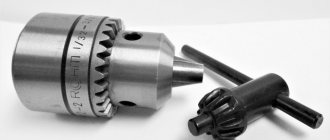
The most common three-piece self-centering cartridge is shown in Fig. 21, a. There are three jaws located in the radial slots of the housing/chuck. With their spiral protrusions on the sole, the cams fit into the grooves of the spiral thread of the bevel gear. THREE-JAW SELF-CENTERING - RUNNING CHUCK:
A - general view, b - device; 1 - body, 2 - cams, 3 - bevel gears, 4 - conical disk with spiral thread, 5 - faceplate, 6 - intermediate disk, 7 - key
Ca 3. This wheel is driven into rotation using a key 7 inserted into the socket of one of the three small gears 3 mated to a large conical disk 4 (Fig. 21.6). Along the spiral thread of the large bevel wheel, the chuck jaws can simultaneously move toward or away from the center, i.e., clamp or release the workpiece.
The radii of curvature in different sections of the spiral thread of the bevel wheel are different, and the radii of curvature of the spiral protrusions of the cams are the same, therefore the contact of the protrusions of the cams and the turns of the spiral thread occurs along narrow areas. This causes significant specific pressures and leads to accelerated wear of the jaws, which is a significant disadvantage of spiral chucks.
It is recommended to have two three-jaw chucks at the turner’s workplace: one for roughing work, the second with non-hardened jaws for finishing work. For some work, for example, for fastening thin-walled workpieces, when ordinary cams can cause the walls to deflect, wide cams (Fig. 22, a) or a split bushing (Fig. 22.6) are used. For the manufacture of precision parts, chucks with replaceable non-hardened jaws are used. Workpieces of large diameters are secured in inverted cams; in this case, the ledges of the cams create a reliable support for the workpiece (Fig. 23). The working surfaces of the cams of a self-centering chuck wear unevenly, so they are periodically bored or ground.
In order not to damage the machined surface of the part, replaceable attachment rings can be attached to solid hardened jaws (Fig. 24), which are then bored
According to the diameter of the surface of the workpiece being fixed[1]
.
22 securing thin-walled workpieces in a three-jaw chuck:
A—using wide cams, b—using a split bushing
23 securing the workpiece in the reversed jaws of the chuck:
1—chuck body, 2—cam
The numbers 1, 2, 3 or the corresponding number of punched points are marked on the grooves of the cartridge body and on the cams. When assembling the cartridge, the cams are inserted into the grooves one by one and in the order of increasing numbers (dots).
Four-jaw simple chuck. The chuck has four clamping jaws that move independently of one another in the grooves of housing 1 (Fig. 25). Each cam has a “half-nut” that mates with a screw located in a groove. To secure the workpiece in
25. four-jaw chuck:
1 — cartridge body (faceplate), 2 — cams, 3 — screw socket, 4 — key
In the chuck, key 4 is inserted into the socket of screw 3.
Collet chucks. It is advisable to secure workpieces with a diameter of up to 60 mm with a pre-treated surface not in a jaw chuck, but in a crimping collet chuck (Fig. 26, a).
Collet 4 (thin-walled steel sleeve with slots), compressed, when screwing nut 1 onto the thread of the cylindrical section of the cartridge body 3, enters the conical bore of the body.
26. collet chucks:
A - with an insert collet, b - solid cast iron; 1 - pressure nut, 2 - adjustable stop, 3 - body, 4 - collet, 5 - screw, 6 - fixing bar, 7 - installation sleeve
The cartridge collet (Fig. 26.6) is made of gray cast iron (SCh18-32). This chuck is easy to manufacture and provides secure fastening no less than a chuck with a steel collet. The final clamping surface of the cast iron collet is bored on the machine on which the workpiece will be processed. Operation of lathe chucks. When securing a workpiece in a chuck, do not use extensions for the wrench handle. When securing and releasing the workpiece, the key handle is grabbed with both hands (at its ends).
Purpose.
The self-centering three-jaw lathe chuck belongs to the class of spiral-rack self-centering three-jaw chucks with a cylindrical belt and mounting on a lathe through an intermediate flange. Self-centering spiral rack lathe chucks are designed for installation on universal lathes, turrets, and internal grinding machines.
They are used in conditions of single, small-scale and mass production. Three-jaw self-centering chucks hold round and hexagonal workpieces or round rods of large diameter. Unlike wedge-type lathe chucks, they do not require time for readjustment in the case when installation to a different clamping diameter is required.
Types and purpose of turning jaws
All turning cams are divided according to their design into several types:
- straight for fixing the part from the outside;
- overhead for securing large diameter workpieces;
- reverse for fixing the part from the inside;
- prefabricated, having a special rail on which the overhead cam is attached.
Types of jaws for lathe chucks with main characteristics
Straight jaws
Straight cams are usually used to fix parts. Each of them has two stages for fastening parts using the “unclamp” method and one prism that works in compression. The working platforms of the cam steps, against which the ends of the workpiece rest, eliminate runout.
Using straight jaws for a lathe chuck, attach:
- small-sized parts (with the surface of the prism - behind the outer side of the part);
- large-sized parts (the surface of the steps is hollow workpieces).
Picture and diagram of a straight cam
Reverse cams
Reverse jaws for a lathe chuck are opposite in design to straight jaws and are used for fastening “in compression” the outer side of parts with a large diameter. The outer surfaces of these cams can be used to install an auxiliary fastening base that works to “unclamp” the inner surface of the workpiece.
Reverse cam picture and diagram
Raw cams
They have a second name - “soft cams” - and are used as blanks for boring a part to the desired diameter, followed by heat treatment. Raw cams are made by turners using steel or non-ferrous metals as the material. Unlike other types of cams, these are not hardened (hence the name).
The raw jaws are attached to the rails that come with the chuck. Raw overhead cams are made according to the shape and dimensions of the parts to ensure the necessary centering accuracy.
Picture and diagram of a raw cam
Composite jaws
Prefabricated jaws for a lathe are also called universal and compound. The equipment consists of two parts:
- the lower one, which is a rack with combs and moves along a spiral disk;
- top cover with standard hardening of the working area.
The design of the pads is reversible cams (direct-reverse). To change the type of equipment, just unscrew two bolts on each cam, turn it to the desired side and fix it again with the bolts on the rail.
Thanks to their versatility, prefabricated jaws reduce preparation time for machining parts when operations require frequent changes from reverse to forward and reverse jaws. There is one caveat: the use of universal equipment causes an error, so it should only be used on lathe chucks with a diameter of 250 millimeters or more. In this case, the relative error can be neglected, and the labor costs for reinstalling the part will be reduced significantly.
Picture and diagram of the assembly cam
Specifications.
The chuck body is made of high quality special cast iron
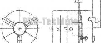
Fig. 1 - General view and main dimensions of a three-jaw lathe chuck.
Technical characteristics of the lathe chuck are given in Table 1
Table 1
| Name of parameters | Values |
| Outer diameter D, mm | 250 |
| Diameter of connecting belt D2, mm | 200H7 |
| Diameter of hole in housing D1, mm | 76 |
| Diameter of mounting holes, mm, D3 | 224 |
| Outer diameter of the product clamped in straight jaws, largest mm | 120 |
| Outer diameter of the product clamped in the return jaws, largest mm | 266 |
| Maximum permissible rotation speed, min ' | 2000 |
| Flange side height | 5 |
| Chuck height without jaws | 85 |
| Height of chuck assembly | 119 |
| Cartridge weight, kg | 29 |
| Fasteners | 6 M12 bolts |
Using a lathe chuck, using straight and reverse jaws, you can clamp workpieces in the following range of sizes
The straight cam is designed to secure the workpiece to the outer surface of the shaft or to the inner surface of the hole in the workpiece. The reverse cam is designed to secure the workpiece to the outer surface.
Accuracy characteristics of lathe chuck
Fig.2.1 - Lathe chuck at idle speed
the cartridge provides the following accuracy characteristics: Radial runout a – 0.045 mm;
End runout c – 0.025mm.
By securing the workpiece in the chuck, the following characteristics can be achieved:
Rice. 2.2 - Lathe chuck with straight jaws attached to the outer surface of the workpiece.
range of fixed workpieces from 5 to 118mm;
Radial runout a at a length of 80 mm is 0.040 mm.
Rice. 2.3 - Lathe chuck with workpiece fastened to the outer surface with reverse cams.
range of fixed workpieces from 77 to 188 mm and from 160 to 250 mm;
Radial runout a – 0.045mm;
End runout c – 0.025mm.
Rice. 2.4 - Lathe chuck with workpiece fastened to the inner surface with straight jaws.
range of fixed workpieces from 62 to 174 mm and from 145 to 256 mm;
Radial runout a – 0.045mm;
End runout c – 0.025mm.
Classifications
Conventionally divided into two groups:
- Cam. Movable segments (cams) fix the part. They differ from each other in design and purpose.
- Collet. Depending on the working position of the collet, which secures the part in the desired position, lathe chucks of this type are distinguished:
- with retractable collet;
- fixed collet;
- retractable collet.
Double cam
Self-centering double-jaw chucks. All parts of the product are made of steel; moving parts are subjected to heat treatment, which increases their strength characteristics and wear resistance.
Provide self-centering and fixation of untreated surfaces of workpieces. The dimensions of the working diameter of the chuck are standardized and vary from 125 to 400 mm.
Mounting cartridge used:
- complex shaped parts;
- non-cylindrical and asymmetrical workpieces.
Three-jaw
The locking mechanism of the 3-jaw chuck is made:
- with rack and pinion mechanism;
- with spiral disc.
Rack and pinion
More precisely, a chuck with a spiral disk has a more powerful clamping of the workpiece. Can be used in small-scale or piece production.
Four-jaw
The four-jaw chuck is used when processing asymmetrical workpieces. Allows you to machine a part off-center or when boring holes along different axes.
The product is attached by two pairs of independent holders in mutually perpendicular planes and ensures complete alignment of the spindle axis with the surface being processed.
The cam can be solid or assembled. The chuck with a prefabricated jaw has a base and a mounted jaw. The assembly cam is placed in the groove of the main element and has free radial movement without loss of stability.
This ensures double keyed fastening. The advantage of the design is the rigidity of fixation and ease of use.
Six-jaw
The fixing force is distributed between six cams, which allows you to fasten a thin-walled part without fear of its destruction or deformation.
Device and principle of operation.
3.1. The design of a spiral rack lathe chuck is shown in Fig. 3.
Fig. 3 - Design of a spiral rack lathe chuck.
Cams 1 , 2 and 3 of the cartridge move simultaneously using disk 4 . On one side of this disk there are grooves (shaped like an Archimedean spiral) in which the lower protrusions of the cams are located, and on the other there is a cut bevel gear mated to three bevel gears 5 . When you turn one of the wheels 5 disk 4 (thanks to gearing) also turns and, by means of a spiral, simultaneously and evenly moves all three cams along the grooves of the cartridge body 6 . Depending on the direction of rotation of the disk, the cams move closer to the center of the chuck or move away from it, clamping or releasing the part. The cams are made in three stages and are hardened to increase wear resistance.
Types of lathe chucks depending on the locking mechanism
The level of radial runout, the speed of changeover, and the possibility of use in single and large-scale production depend on the correct choice of the type of lathe chuck with the appropriate locking mechanism. The main most commonly used types of machines:
Collet
This type of fastener is a bushing with axial slots in which locking tabs are located.
From a design point of view, this type of chuck includes a feed collet with blades and a bushing.
Collet models are used for the following purposes:
However, they also have their disadvantages, which include the relatively small diameters of the workpieces.
Lever
Until recently, this variety was considered the most popular. The principle of their operation is based on the movement of the clamping jaws by moving a special lever. It is also worth noting that for more precise adjustment, the design is equipped with a hydraulic drive.
And also during operation, sometimes there is an insignificant play of the workpiece during rotation. Therefore, lever-type clamps are used primarily for roughing purposes.
Wedge
This option is an improved version of the lever version of the product. Greater precision is achieved here due to the fact that each individual cam is equipped with its own mechanical or pneumatic drive.
These designs are used for precision turning. The advantage of wedge lathe chucks is the ability to move the central part of the part relative to the rotating axis. From this we can conclude that they can be used to make even complex parts.
These parts are characterized by the following features:
For CNC equipment, the ability to quickly change settings is extremely important. Therefore, such machines use special cartridges that are connected directly to the control unit.
It is also important that the materials from which wedge-type cartridges are made have specific requirements. In most cases, the processing process involves the use of high speeds, therefore the quality of the clamping device must remain unchanged.
Warranty obligations.
The warranty period for the product is 1 year, from the date of sale (receipt by the buyer) of the three-jaw chuck, provided that the consumer complies with the rules for storing and operating the product.
download the technical data sheet for free using the link below.
Cam lathe chuck: description, diagram. Varieties by type of clamp, fixation, design, accuracy class. How to make your own cartridge.
The cam lathe chuck is a necessary component for a lathe. The final result of the work depends on the quality of the clamping device. In particular, if the chuck does not provide the greatest clamping force, the part may simply fly off the front end of the spindle. The device is responsible for the accuracy of centering and influences whether the processing axis will be exactly perpendicular to it. Of course, the issue of choosing a component should be taken very seriously, since it determines the effectiveness of the procedure and the quality of the resulting parts.
General concepts about lathe chucks
Lathe chucks are selected depending on the technical characteristics of the device and the spindle, in particular. They represent the main components of the equipment. The mechanism is a cam effect. Dimensions are selected depending on the parameters of the unique workpiece.
The cams ensure reliable fixation of the mechanism. Due to the action of mechanical force, which determines the tightness of the fastening, installation and fastening occurs. The workpiece is fixed using a chuck.
It should be taken into account that the parts that need to be processed have different sizes and diameters.
A low-quality cartridge will not hold as tightly as possible; as a result of strong mechanical movement, it can fly off, and the workpiece with it. The chuck ensures smooth movement of the fastener, while the workpiece will not move relative to the center. In the simplest sense of the word, a chuck is a mechanism that is responsible for rotating the workpiece, making its processing efficient and smooth.
Current GOSTs
Regulates the parameters of lathe chucks GOST 1654-86. It regulates the technical conditions of general-purpose cartridges. Many other standards also apply. Thus, self-centering 3-jaw chucks are regulated by GOST 2675-80. GOST 14903-69 applies to two-jaw clamps with self-centering.
News
Delivery - as usual
Targeted delivery to the transport company
Congratulations on March 8th!
Happy International Women's Day!
Congratulations on February 23!
Congratulations on Defender of the Fatherland Day!
Articles
Reaming holes
Application, procedure and tool used
Dimensions and diameters of drills for metal
Selecting the diameter and length of the drill
Purpose
Inside the type of part in question is a cam mechanism. This important component allows you to center and clamp the workpiece. This happens due to the narrowing of the cam parts, and then clamping them with a quill. Only after the part has been completely secured can you begin working on a wood or metal lathe. If the procedure is not followed, the workpiece may not only fall out or be damaged, but also cause harm to the master.
You should carefully check the quality of fastening of the part in the chuck. First, specialists turn on the lathe at low power and see if the mechanism rotates well. If after a few laps everything is in order, they will continue to work at higher powers.
Communities › Machine Tools and Machine Work › Blog › Tell us about the chuck for a lathe.
I can’t find information anywhere about how to correctly determine where and how the jaws should be positioned in the chuck. I have a 3 jaw chuck. How to understand where the zero crack is? How should the cams be positioned relative to the zero cracker? Is there anything different about breadcrumbs? Why is it called zero?
On my cartridge there are diameters stamped on the cartridge, and there is a cracker above them. Did I understand correctly that it will be zero and there will be the first cam under it. Is it somehow possible to visually understand that the cracker is zero and where it should be in the cartridge?
I figured out the cams more or less, but I couldn’t find anything about the crackers. I had already filled in the big numbers myself, but there were the rest.
Classification of lathe chucks
There are several types of classifications: according to the number of cams, type of clamp, fixation mechanism, type of execution, accuracy class.
By the number of jaws in the chuck
Cams are responsible for the quality of fastening of parts. They are made of high quality metal.
Double cam
Options secure asymmetrical parts that are not processed. But they are also used for standardized workpieces.
Three-jaw
Optimal for producing hexagonal and round variations. Shunting occurs on three sides of the cams.
Four-jaw
The 4 jaw chuck consists of four units that function independently. Used for processing rectangular and square options.
By type of workpiece clamp
The chuck jaws are divided into direct and reverse. Virtually no effect on performance. Selected depending on the type of cartridge input.
Direct
The clamping occurs externally. The cams are located on top and grab the part.
Reverse
Clamping occurs from the inside, from the inside. The object being processed is chosen to be hollow, so that it can catch on.
According to the workpiece fixation mechanism
The fixation mechanism is an important characteristic that determines the quality of work.
Three jaw chucks
The most common chucks are three-jaw chucks. They are installed on all turning equipment: in home workshops, garages, repair shops, small- and large-scale production.
The most common are 3 types of self-centering chucks:
Three-jaw chucks are equipped with a traction (clamping elements are connected to a hydraulic or pneumatic drive) or a built-in drive. Up to thirty percent of auxiliary time is spent on clamping the workpiece during operation, so the devices are mechanized and reduce the time for installing the product. The most widely used in large-scale and mass production are powered jaw chucks with pneumatic drive. The hydraulic drive is rarely used and is used in situations where it is necessary to maintain small dimensions of the structure. The main advantage of mechanized units is speed and constant clamping force on the jaws.
Detailed video on clamping turning units
Spiral cartridges
3-jaw scroll chucks have been around for over 100 years and, due to their simple design and reliability, are still used in new equipment today. They provide a large range of cam travel and have high efficiency; it is possible to clamp eccentric and non-round workpieces. The disadvantages are rapid loss of accuracy and accelerated wear. The loss of initial accuracy occurs as a result of technological features: the volute is only improving and has low hardness, therefore, it quickly wears out - rapid wear of the centering mechanism occurs. Accelerated wear occurs due to chips and dirt getting into the wedge-shaped gaps between the teeth of the cams.
Used in single and small-scale production. Equipped with direct and reverse cams.
Rack chucks
3-jaw rack chucks get their name because of the principle of operation: a gear rim moves the racks, which simultaneously moves the jaws. More durable than spiral ones, because It is possible to harden and grind the teeth. The body is made of cast or forged steel, the remaining moving parts are alloyed, followed by hardening. They are universal and are used in single or small-scale production.
- stronger clamp;
- greater accuracy;
- Efficiency is lower than that of spiral ones;
- Possibility of clamping from only one position;
- complex design.
Eccentric chucks
3-jaw eccentric chucks are used in large-scale production. All parts of the unit are made of wear-resistant steels, and then undergo hardening and grinding. They have high precision and clamping force. They can be re-adjusted to clamp another part relatively simply - by rearranging the mounted cams.
By type of execution
In the Russian Federation, the types of cartridges by design are regulated by GOST 2675 - 80.
Whole
Made from a piece of steel with parameters starting from 500 MPa. The most common type.
Made
A rail is made of steel, and a cam is attached to it. The latter is made of metal.
Overhead
Composite variations consist of non-ferrous metal, stainless steel, ferrous metals. Used for working with large-scale projects.
Wood lathe chucks, types and how to make them yourself
To choose the optimal type of product, you need to study the technical characteristics of its different models. They directly depend on the type of operations performed by the lathe.
Lathe chucks for working with wood are distinguished by the following characteristics:
The body of the lathe chuck for the machine is made of special cast iron with indicators not lower than SCh-30. For the manufacture of other elements, special steel with a tensile strength of 500 MPa or more is used. The roughness of the material also has different values: for working surfaces it is 1.6, and for a protruding cylindrical part it is no more than 0.8.
Cartridge accuracy classes
The accuracy of the device is determined in GOST 1654 86. There are four stages in total.
Class H
Normal indicators, averaged.
Class P
Higher class, used for making hard production parts.
Class B
High accuracy - used for processing small variations.
Class A
Particularly high accuracy. Scope of application: small and hard workpieces.
Chuck design: diagram and description
A lathe chuck consists of more than ten parts. Efficiency and service life are determined by the quality of the assembly and the material used to manufacture the set of parts.
The main mechanism responsible for moving the workpiece on a lathe. It helps to secure the object being processed.
Spring
Attached to the key. Responsible for the turns of the latter.
Sleeve
Connected to a spring. Necessary to ensure free movement of the key through the mechanism.
Stopper
Connected with bushing and key. It is the main mechanism that is responsible for safety. The stopper controls the fixation of the workpiece and prevents it from falling off.
Gear
The disk, with the help of which the rotational movement occurs, is driven by a gear.
Flange
It is the base of the lathe chuck. Connects mechanisms to each other.
Spiral disc
Connects to gear. Responsible for receiving rotation. Regulates the degree and speed of processing.
Reverse cam
The mechanism is responsible for fastening the workpiece from the inside.
Cam straight
Direct variation is necessary to secure the object from the outside.
Frame
Necessary for securing the sides. Provides structural protection in a common equipment assembly.
Overhead cams
Contribute to the establishment of work with non-standard shaped workpieces. Used when you need to place an option with a large diameter or a smaller, longer length.
Making a lathe chuck for wood with your own hands
The manufacture of jaw chucks requires high-precision industrial equipment and it is hardly possible to make them in a home workshop. However, there are simpler designs that are not difficult to build with your own hands.
Homemade wood turning faceplate with adjustable clamps
You will need a flat sheet of steel with a thickness of at least 10 mm, a steel angle 50x50 mm, eight M8x30 bolts with nuts and washers. You should think in advance about how the device will be mounted on the machine and, if necessary, make or purchase an appropriate threaded bushing. After this you can proceed:
To fix it with such a homemade cartridge, the corners are moved to the desired position and secured by tightening the nuts; the part is finally tightened with bolts screwed into the threaded shelves.
If your lathe's headstock spindle has a through hole for knocking out the gear center, you can add a homemade vacuum chuck to your arsenal. For this you will need:
A bushing is machined from the textolite, one side of which should be equal in diameter to the internal size of the bearing, the other - to the spindle. This homemade adapter is pressed into the bearing using glue; it will be held in the machine due to the tightness of the fit. The resulting structure is connected with a piece of hose to the vacuum cleaner and secured with a clamp.
Self-assembly of the cartridge according to the drawings
Self-assembly does not take much time. This is a fairly simple process. The main thing is to understand the mechanism of operation of the device. As a last resort, you can order such miniature equipment from a professional turner. He will assemble any variation from the available parts. Homemade models cost significantly less than those ordered from production.
The quality may be even better than factory ones.
Installation of the mandrel
The frame is put on first. Installing the part makes it possible to secure the cartridge.
Installing the chuck itself on the spindle
The mechanism is being secured. Do not press or bore parts. At this stage, fastening occurs with previously prepared bolts of suitable size.
Consolidation
After checking the quality of the wrapping, the final assembly of the mechanism is carried out. The bolts are screwed using a wrench.
Securing the workpiece
Tools are installed on a homemade cartridge. Carried out after checking the assembly with bolts.
Installation and fastening of parts in chucks
Scroll chuck
Short parts are usually installed and secured in chucks, which are divided into simple and self-centering.
Four jaw chucks
Simple chucks are usually made with four jaws (Fig. 41). In such chucks, each of the four cams (1, 2, 3 and 5) is moved by its own screw 4 independently of the others. This allows you to install and secure parts with an asymmetrical external shape. When securing a part in a four-jaw chuck, it is necessary to install it correctly so that it does not hit when rotating.
Rice. 41 Simple four-jaw chuck
Rice. 42. Checking the installation of the part using a thickness planer
The correct installation of the part can be checked using a thicknesser scriber (Fig. 42). The thicknesser scriber is brought to the surface being tested, leaving a gap of 0.3-0.5 mm between them. The parts report slow rotation and monitor how this gap changes. Based on the observation results, some cams are pressed out and others are pressed in until the gap becomes uniform around the entire circumference of the part. After this, the part is finally secured with all four cams, pressing them evenly with a key one after the other.
After securing the part in the chuck, be sure to remove the key. If this is not done, the machine may break during startup; in addition, the worker is exposed to the risk of injury.
Self-centering chucks
Self-centering chucks (Fig. 43) are in most cases three-jaw and much less often two-jaw. These chucks are very convenient to use, since all the cams move simultaneously, due to which a part having a cylindrical surface (external or internal) is installed and clamped exactly along the axis of the spindle; In addition, the time required to install and secure the part is significantly reduced.
In Fig. 43, and a three-jaw self-centering chuck is shown. In it, the cams are moved using a square socket wrench, which is inserted into the tetrahedral hole 1 (Fig. 43, a and b) of one of the three bevel gears 2. These wheels are engaged with a large bevel gear 3. On the back flat side of the wheel 3 is threaded multi-turn spiral groove 4 (Fig. 43, b). All three cams 5 enter into the individual turns of this groove with their lower projections. When one of the gears 2 is turned with a wrench, the rotation is transferred to the gear 3. Rotating, it moves all three cams simultaneously and evenly along the grooves of the cartridge body through the spiral groove 4. As the spiral-groove disk rotates in one direction or the other, the cams move closer or further from the center, respectively clamping or releasing the part.
It is necessary to pay attention to the strong clamping of the part in the jaws of the chuck. If the cartridge is in good condition, then a strong clamping of the part is ensured by using a key with a normal handle (Fig.
44). Other clamping methods, for example clamping with a key and a long pipe placed on the handle, are prohibited.
Fig 43 - Three-jaw self-centering chuck
Rice. 44. Installing and securing the part in the chuck and rear center
After clamping a part, do not leave the key in the chuck, as this may lead to an accident or equipment failure.
Chuck jaws
The chuck jaws are used hardened and raw. Hardened cams are usually used because they wear out slowly. But when clamped with such jaws, marks in the form of dents from the jaws remain on parts with cleanly machined surfaces. To avoid dents, in these cases it is recommended to use raw (unhardened) cams, which are precisely processed (fitted) to the diameter of the part fixed in them.
Raw jaws are also convenient because they can be periodically bored with a cutter and thereby eliminate the chuck runout, which is inevitable during long-term operation. The cams are bored exactly to the size of the part being fixed in them.
Installation and fastening of parts in a chuck with support from the rear center is used when processing long and relatively thin parts (Fig. 44), which are not sufficient to be secured only in the chuck, since the cutting force and the weight of the protruding part of the part can bend it and tear it out of the chuck.
When removing the part, press the jaws onto the chuck and, supporting the part with your left hand, remove the rear center from it, for which you rotate the tailstock handwheel with your right hand.
