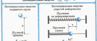
Definition and formula of spring stiffness
When considering what a spring constant is, attention should be paid to the concept of elasticity. The symbol F is used to designate it. In this case, the elastic force of the spring is characterized by the following features:
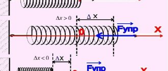
- It appears exclusively when the body is deformed and disappears if the deformation disappears.
- When considering what spring stiffness is, it should be taken into account that after the external load is removed, the body can restore its size and shape, partially or completely. In such a case, the deformation is considered elastic.
Do not forget that rigidity is a characteristic characteristic of elastic bodies capable of deformation. A fairly common question is how spring stiffness is indicated on drawings or in technical documentation. The letter k is most often used for this.
Too much deformation of the body causes various defects to appear. The key features are the following:
- The part can maintain its geometric parameters during long-term use.
- As the index increases, the compression of the spring under the influence of the same force decreases significantly.
- The most important parameter can be called the stiffness coefficient. It depends on the geometric parameters of the product and the type of material used in manufacturing.
Red springs of another type have become quite widespread. Color designation is used in the production of automotive products. The following formula is used for calculation: k=Gd4/8D3n. This formula contains the following notations:
- G – used to determine the shear modulus. It is worth considering that this property largely depends on the material used in the manufacture of the coils.
- d – diametrical indicator of the wire. It is produced by rolling. This parameter is also indicated in the technical documentation.
- D is the diameter of the turns created when the wire is wound around the axis. It is selected depending on the tasks assigned. In many ways, the diameter determines how much load is applied to compress the device.
- n – number of turns. This indicator can vary over a fairly wide range and also affects the basic performance characteristics of the product.
The formula under consideration is used in the case of calculating the stiffness coefficient for cylindrical springs, which are installed in a wide variety of mechanisms. This unit is measured in Newtons. The stiffness coefficient for standardized products can be found in the technical literature.
Practical lessons
Mechanics and physicists use k, c and D to denote the coefficient of elasticity, proportionality, and rigidity. The meaning of the mathematical notation is the same. Numerically, the indicator is equal to the force that creates vibrations per unit of length. In practical work in physics, 1 meter is used as the last value.
The higher k, the greater the object's resistance to deformation. Additionally, the coefficient shows the degree of resistance of the body to vibrations from external loads. The parameter depends on the length and diameter of the screw product, the number of turns, and raw materials. The unit of spring stiffness is N/m.
In practice, schoolchildren and mechanics may be faced with a more difficult task, for example, finding the overall stiffness. In this case, the springs are connected in series or parallel. In the first case, the total stiffness decreases. If the springs are arranged in series, the following formula is used: 1/k = 1/k1 + 1/k2 + … + 1/ki, where:
- k is the total stiffness of the connections;
- k1 …ki is the stiffness of each element of the system;
- i is the number of springs in the chain.
If weightless (horizontal) objects are connected in parallel, the value of the total k will increase. The value is calculated using the following formula: k = k1 + k2 + … + ki.
Basic method for calculations
In practice, Hooke's coefficient is determined independently. For the experiment you will need a spring, a ruler, and a weight with a certain mass. The following sequence of actions must be followed:
- The spring is fixed vertically. To do this, use any convenient support with a free lower part.
- A ruler measures the length of an object. The result is written as x1.
- A load with a known mass m is suspended from the free end.
- The length of the product is measured under the influence of amplitude. The output is written as x2.
- Calculates the absolute elongation: x = x2-x1. To determine energy (force) and k in the international SI system, length is converted from different units of measurement to meters.
- The force that provoked the deformation is considered to be the force of gravity of the body. It is calculated by the formula: F = mg, where m is the mass of the load used (weight is converted to kilograms), and g (equal to 9.8) is a constant value with which the acceleration of free fall is noted.
If the above calculations are made, it is necessary to find the value of the stiffness coefficient. Hooke's law is used, from which it follows that k=F/x.
Problem solving
To find stiffness in the case of using different objects, including spring pendulums with different oscillation frequencies, Hooke’s formula or a corollary arising from it is used.
Problem No. 1. A spring has a length of 10 cm. A force of 100 N is exerted on it. The product is stretched by 14 cm. We need to find k.
Solution: the absolute elongation is pre-calculated: 14−10=4 cm. The result is converted into meters: 0.04 m. Using the basic formula, k is found. Its value is 2500 N/m.
Problem No. 2. A load weighing 10 kg is suspended from a spring. The product stretches by 4 cm. You need to find the length to which the spring will stretch if you use a load weighing 25 kg.
Solution: The force of gravity is determined by multiplying 10 kg by 9.8. The result is recorded in Newtons. K=98/0.04=2450 N/m is determined. The force with which the second load acts is calculated: F=mg=245 N. To find the absolute elongation, the formula x=F/k is used. In the second case, x equals 0.1 m.
Spring connection stiffness formula
Do not forget that in some cases the body is connected by several springs. Such systems have become very widespread. Determining rigidity in this case is much more difficult. Among the features of the connection, the following points can be noted:
- A parallel connection is characterized by the fact that the parts are placed in series. This method can significantly increase the elasticity of the created system.
- The sequential method is characterized by the fact that the parts are connected to each other. This method of connection significantly reduces the degree of elasticity, but allows a significant increase in maximum elongation. In some cases, it is the maximum extension that is required.
In both cases, a certain formula is used that determines the characteristics of the connection. The modulus of elastic force may vary significantly depending on the characteristics of a particular product.
When connecting products in series, the indicator is calculated as follows: 1/k=1/k1+1/k2+…+1/kn. The indicator in question is considered a rather important property, in this case it decreases. The parallel connection method is calculated as follows: k=k1+k2+…kn.
Such formulas can be used in a wide variety of calculations, most often at the time of solving mathematical problems.
Elastic force.
The author is a professional tutor, author of textbooks for preparing for the Unified State Exam Igor Vyacheslavovich Yakovlev
Topics of the Unified State Examination codifier: forces in mechanics, elastic force, Hooke's law.
As we know, on the right side of Newton’s second law is the resultant (that is, the vector sum) of all forces applied to the body. Now we have to study the forces of interaction between bodies in mechanics. There are three types: elastic force, gravitational force and friction force. We start with elastic force.
Spring connection stiffness coefficient
The above indicator of the stiffness coefficient of a part for a parallel or series connection determines many characteristics of the connection. Quite often it is determined what the elongation of a spring is. Among the features of a parallel or serial connection, the following points can be noted:
- When connected in parallel, the elongation of both products will be equal. Do not forget that both options must have the same length in the free position. With sequential, the indicator doubles.
- Free position - a situation in which the part is located without applying a load. This is what is taken into account in calculations in most cases.
- The stiffness coefficient varies depending on the connection method used. In the case of a parallel connection, the indicator doubles, and in a serial connection it decreases.
To carry out calculations, you need to build a connection diagram for all elements. The base is represented by a hatched line, the product is indicated schematically, and the body in a simplified form. In addition, kinetic and other energy largely depends on elastic deformation.
Examples of problems with solutions
Exercise. The spring in no load has a length of $l=0.01$ m and a stiffness equal to 10 $frac. $What will the spring stiffness and its length be equal to if a force $F$= 2 N is applied to the spring? Consider the spring deformation to be small and elastic.
Solution. The spring stiffness during elastic deformations is a constant value, which means that in our problem:
For elastic deformations, Hooke's law is satisfied:
[F=kDelta l left(1.2right).]
From (1.2) we find the extension of the spring:
The length of the stretched spring is:
Let's calculate the new length of the spring:
Answer. 1) $k'=10 frac$; 2) $l'=0.21$ m
Exercise. Two springs with stiffnesses $k_1$ and $k_2$ are connected in series. What will be the elongation of the first spring (Fig. 3) if the length of the second spring increases by $Delta l_2$?
Solution. If the springs are connected in series, then the deforming force ($overline$) acting on each of the springs is the same, that is, we can write for the first spring:
For the second spring we write:
If the left sides of expressions (2.1) and (2.2) are equal, then the right sides can also be equated:
[k_1Delta l_1=k_2Delta l_2left(2.3right).]
From equality (2.3) we obtain the elongation of the first spring:
Answer. $Delta l_1=frac$
Source: www.webmath.ru
Coil spring stiffness coefficient
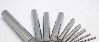
In practice and in physics, it is cylindrical springs that have become quite widespread. Their key features include the following:
- When creating, a central axis is specified, along which most of the various forces act.
- In the production of the product in question, wire of a certain diameter is used. It is made of a special alloy or ordinary metals. Do not forget that the material must have increased elasticity.
- The wire is wound in turns along the axis. It is worth considering that they can be the same or different diameters. The cylindrical version has become quite widespread, but the cylindrical version is characterized by greater stability; in the compressed state, the part has a small thickness.
- The main parameters include the large, medium and small diameter of the turns, the diameter of the wire, and the pitch of the individual rings.
Do not forget that there are two types of parts: compression and tension. Their stiffness coefficient is determined by the same formula. The difference is this:
- The compression version is characterized by a distant arrangement of turns. Due to the distance between them, compression is possible.
- The model, designed for stretching, has rings located almost closely. This shape determines that maximum elastic force is achieved with minimal stretching.
- There is also a design option that is designed for torsion and bending. Such a detail is calculated using certain formulas.
Calculation of the coefficient of a cylindrical spring can be carried out using the previously specified formula. It determines that the indicator depends on the following parameters:
- Outer radius of the rings. As previously noted, when manufacturing a part, an axis is used, around which the rings are wound. At the same time, do not forget that the average and inner diameters are also distinguished. A similar indicator is indicated in the technical documentation and drawings.
- The number of turns created. This parameter largely determines the free length of the product. In addition, the number of rings determines the stiffness coefficient and many other parameters.
- The radius of the wire used. The starting material is wire, which is made from various alloys. In many ways, its properties influence the quality of the product in question.
- Shear modulus, which depends on the type of material used.
The stiffness coefficient is considered one of the most important parameters, which is taken into account when carrying out a variety of calculations.
Units
When carrying out calculations, the units of measurement in which the calculations are carried out must also be taken into account. When considering what the elongation of a spring is, attention is paid to the unit of measurement in Newtons.
In order to simplify the selection of a part, many manufacturers indicate it by color designation.
The division of springs by color is carried out in the automotive industry.
Among the features of such marking we note the following:
- Class A is indicated by white, yellow, orange and brown shades.
- Class B is available in blue, cyan, black and yellow.
As a rule, a similar property is noted on the outside of the coil. Manufacturers apply a small strip, which greatly simplifies the selection process.
Features of calculating the stiffness of spring connections
The above information indicates that the stiffness coefficient is a fairly important parameter that must be calculated when choosing the most suitable product and in many other cases. That is why a fairly common question is how to find the spring stiffness. Among the features of the connection, we note the following:
- The spring stretch can be determined during the calculation, as well as at the time of the test. This indicator may depend on the wire and other parameters.
- A variety of formulas can be used for calculations, and the resulting result will be practically error-free.
- It is possible to conduct tests, during which the main parameters are identified. This can only be determined by using special equipment.
As previously noted, there are serial and parallel connection methods. Both are characterized by their own specific characteristics that must be taken into account.
In conclusion, we note that the part in question is an important part of the design of various mechanisms. An incorrect design will not last for a long period. At the same time, we should not forget that too much deformation causes deterioration in performance characteristics.
Types of deformation
Deformation is a change in the shape or size of the body.
There are several types of deformation:
- shift;
- torsion;
- bend;
- compression/extension;
Shear deformation occurs when some parts of the body move relative to other parts of the body. If we apply a horizontal force to the top of a cardboard box filled with various objects, we will cause the top of the box to shift relative to its bottom.
Compression or stretching is easy to imagine using the example of a rectangular piece of thin rubber. This deformation is used, for example, in elastic bands for clothing.
Examples of bending and torsion are shown in Figure 1. A plastic ruler deformed by bending is shown in Figure 1. 1a, and in Figure 1b - the same ruler deformed by torsion.
Rice. 1. plastic ruler, deformed by bending – a) and torsion – b)
In a deformable body, forces arise that are of an electromagnetic nature and prevent deformation.