Automation of a hydraulic press using the KE-USB24A module
Pneumatic press for perforation and hot stamping
In this article I will describe the design and electrical circuit of a pneumatic press for hot stamping on leather and cardboard, which I assembled with my own hands. Such pneumatic presses can be called differently, depending on the scope of application.
Unlike a hydraulic press, which is driven by a hydraulic pump, a pneumatic press develops pressure using compressed air produced by a compressor.
Based on the diagram and design described in the article, the following types of presses can work: perforation, hot stamping, various presses for molding and gluing parts.
Here, as an example, is my article about installing the Euroautomatika RT-820M temperature relay in a similar Turkish press.
In my case, the press is used in shoe production to hot-stamp the upper part of the shoe. As a result of the action of the press, a beautiful pattern or logo appears on the leather upper of shoes, shoes or boots. When installing a special mold and increasing the pressure, small holes can be drilled.
Agree, boots on a woman’s foot with a beautiful stylized flower on the top look much more impressive!
It is worth saying that a pneumatic press develops less pressure compared to a hydraulic one. But this is in the general case, it all depends on the specific model.
Do-it-yourself pneumatic press: making a pneumatic press from an office chair gas lift
To perform many jobs in industrial and home workshops, it is very convenient to use a pneumatic press, which, by developing sufficient force, greatly facilitates the process of carrying out many technical procedures.
In particular, using such equipment, it is possible to bend metal products, carry out die-cutting operations and hammerless riveting, and use the force that such a press creates for gluing wood products and hot stamping.
It is very convenient that you can make a simple but quite effective pneumatic press with your own hands, and this does not require expensive consumables or special equipment.
Homemade pneumatic press from an office chair gas piston
Preparation of components
Before you start making your own pneumatic press, you should understand the principle of its operation.
If hydraulic presses are driven by a hydraulic pump, then in pneumatic press equipment a device that produces compressed air is used for these purposes. A compressor or air pump can be used as such a device.
Compressed air of a certain pressure is supplied to a pneumatic cylinder or to a membrane-spring pneumatic actuator, on the output rod of which the required pressure is created.
The gas lift device for an office chair allows it to be used as a pneumatic pusher
It should be borne in mind that pneumatic presses, when compared with hydraulic ones, create less pressure, but in many cases it is sufficient to perform certain technological operations.
So, in order to make a simple pneumatic press, you need to prepare:
- pneumatic shock absorber (such shock absorbers are installed on office and computer chairs);
- air pump or small compressor;
- threaded fitting with a diameter of 3 mm;
- connecting hose.
To easily remove the gas lift from the crosspiece, apply penetrating lubricant, remove the locking key and carefully knock the part out of the cone joint.
Manufacturing process
The manufacturing process of the press, the basis of which will be the pneumatic shock absorber from the chair, is carried out according to the following algorithm.
- On the side of the pneumatic shock absorber from the chair, using a marker, mark the place where the threaded fitting will be installed.
- At the marked location, a hole of the appropriate diameter is made, in which a thread is cut to install the fitting.
- The fitting is screwed into the prepared hole, for which it is better to use sealing tape.
- A hose is placed on the upper part of the fitting; for more reliable fixation it is better to use a clamp of the appropriate size.
- The second end of the hose is connected to the outlet fitting of the air pump or compressor and is also secured with a clamp.
Marking the installation location of the fitting
Preparation of components
Before you start making your own pneumatic press, you should understand the principle of its operation. If hydraulic presses are driven by a hydraulic pump, then in pneumatic press equipment a device that produces compressed air is used for these purposes. A compressor or air pump can be used as such a device. Compressed air of a certain pressure is supplied to a pneumatic cylinder or to a membrane-spring pneumatic actuator, on the output rod of which the required pressure is created.
The gas lift device for an office chair allows it to be used as a pneumatic pusher
DIY pneumatic press
To perform many jobs in industrial and home workshops, it is very convenient to use a pneumatic press, which, by developing sufficient force, greatly facilitates the process of carrying out many technical procedures.
In particular, using such equipment, it is possible to bend metal products, carry out die-cutting operations and hammerless riveting, and use the force that such a press creates for gluing wood products and hot stamping.
It is very convenient that you can make a simple but quite effective pneumatic press with your own hands, and this does not require expensive consumables or special equipment.
Homemade pneumatic press from an office chair gas piston
How to make a functional pneumatic press
As mentioned above, pneumatic presses can be used for hot stamping, as well as for veneering any wood materials (natural solid wood, chipboard, MDF, etc.).
However, to solve such problems, not an ordinary, but a hot pneumatic press is used, which you can also make yourself.
The main difference between this press and a conventional type device is that its working part, which exerts pressure on the product being processed, must be heated to a certain temperature.
Heating will be done using heating elements
In order to ensure heating of the working body of a pneumatic press, electric heating elements must be built into the latter, and the working body itself must be made of aluminum to ensure better thermal conductivity. The design of a pneumatic hot press is necessarily complemented by an electrical circuit consisting of two independent parts:
- an electronic unit that is responsible for turning on and heating electric heating elements (the main element of such a unit is a temperature controller that allows it to be maintained with an accuracy of half a degree);
- a block that will provide control of the air valve itself (thanks to the presence of such a block, it is possible not only to control the process of supplying the working element to the surface of the workpiece (as well as removal from it), but also to regulate the holding time of the press in a compressed state).
Thermostat with solid state relay output
Electrical circuit of a press with heating elements
Using such a press with various working attachments, you can solve many practical problems, which, in particular, include:
- performing hot stamping on leather products (shoes, bags, etc.);
- hot gluing of shoe elements;
- veneering wood products;
- design of book covers made of leather or leatherette.
In conclusion, another version of a heated press for cladding furniture panels, which uses elements of an electric heated floor.
Pneumatic press based on timer and temperature controller
Pneumatic press for perforation and hot stamping
In this article I will describe the design and electrical circuit of a pneumatic press for hot stamping on leather and cardboard, which I assembled with my own hands. Such pneumatic presses can be called differently, depending on the scope of application.
Unlike a hydraulic press, which is driven by a hydraulic pump, a pneumatic press develops pressure using compressed air produced by a compressor.
Based on the diagram and design described in the article, the following types of presses can work: perforation, hot stamping, various presses for molding and gluing parts.
Here, as an example, is my article about installing the Euroautomatika RT-820M temperature relay in a similar Turkish press.
Manufacturing process
The manufacturing process of the press, the basis of which will be the pneumatic shock absorber from the chair, is carried out according to the following algorithm.
- On the side of the pneumatic shock absorber from the chair, using a marker, mark the place where the threaded fitting will be installed.
- At the marked location, a hole of the appropriate diameter is made, in which a thread is cut to install the fitting.
- The fitting is screwed into the prepared hole, for which it is better to use sealing tape.
- A hose is placed on the upper part of the fitting; for more reliable fixation it is better to use a clamp of the appropriate size.
- The second end of the hose is connected to the outlet fitting of the air pump or compressor and is also secured with a clamp.
Marking the installation location of the fitting
Now that the pneumatic press is fully assembled, you can test it in operation, for which you just need to turn on the air pump or compressor. Once air from the air supply device begins to flow into the inside of the air spring, the output rod should begin to move. If such a movement occurs, then this indicates the correctness of the actions performed.
Checking the functionality of the mechanism
To make a pneumatic table press more convenient and efficient to use, a metal circle of small diameter can be fixed at the working end of its rod, which, acting on the workpiece, will create pressure over a larger area.
The press of the design proposed above can be easily modified if necessary. In the same form, it can be used to perform simple bending and die-cutting operations. If desired, the resulting structure can be fixed on the base of the pneumatic chair itself, where there are already mounting holes for it. By doing this, you will get a more convenient device to use, installed on a reliable base.
Do-it-yourself pneumatic press: making a pneumatic press from an office chair gas lift
To perform many jobs in industrial and home workshops, it is very convenient to use a pneumatic press, which, by developing sufficient force, greatly facilitates the process of carrying out many technical procedures.
In particular, using such equipment, it is possible to bend metal products, carry out die-cutting operations and hammerless riveting, and use the force that such a press creates for gluing wood products and hot stamping.
It is very convenient that you can make a simple but quite effective pneumatic press with your own hands, and this does not require expensive consumables or special equipment.
Homemade pneumatic press from an office chair gas piston
How to Make a 40 Ton Pneumatic Press Brake
Step one: design, calculations When designing a sheet metal bending machine, the first question is what is the maximum thickness and width of steel that needs to be bent? The craftsman needed to bend 3/16-inch (4.7 mm) thick steel over a 4-foot (121.92 cm) wide area. The result is a fairly large machine.
The calculations used a press brake calculation table for plain steel. On the left side of the table is the choice of steel thickness. At the top of the table are the "v-fold" size options (see illustration in diagram for better understanding). The middle of the diagram shows the force in tons per linear foot.
How to use this chart? Let's say, for example, that the maximum thickness and width of the sheet that needs to be bent is 10 gauge* and 2 feet wide. Look at the left side of the diagram and look for “10 gauge.” Now look at the top of the chart and select the "v-hole" size (a typical v-die size for 10 gauge steel is 1.25 inches). Now look at the center part of the diagram and see where these two choices intersect. The graph shows that 7.3 tons per linear foot is required to make this bend. Since we need to bend a width of 2 feet, it will require 14.6 tons of force.
For this example, we will need a 2-foot wide press brake that can produce at least 14.6 tons of pressure. With this information, you can start designing your own machine.
*Unit of thickness of metal sheets. The larger the caliber, the thinner the sheet. 10 gauge corresponds to a sheet thickness of 0.1345 inches (3.416 mm). An increase in the caliber number by 1 corresponds to a decrease in thickness by 10%.
Before designing, it is good to have a basic understanding of how such machines work. There's nothing too scientific about a press brake. Attached is a sketch showing the main components along with some details below:
The main frame is the basis of the machine. In essence, it is nothing more than a rectangle made of some massive materials. Due to its large size, the craftsman added several legs and wheels.
Bottom jaw - also called "v-shaped matrix". The workpiece will be pressed into the "v-die" to create a bend. Top jaw - Also called bending blade. The bending blade will press on the top of the workpiece and force the material into the "v-die".
The bending knife assembly is simply the assembly that holds the top jaw. It must be strong enough to resist bending deformation
Hydraulic jacks are the muscles of the machine. They create the force necessary for bending. The master has two jacks installed on the machine, but depending on the required power, it is possible to install one.
The return springs will pull the bending knife assembly upward once the bend is complete. The springs must be strong enough to lift the weight of the bending knife assembly.
There are other designs of similar machines, but it was this type of device that best suited the needs of the master.
The master has a wide selection of equipment to use. For example, he has a milling machine that he used to mill my bending dies. But if such a machine does not exist, then you can make a sponge from a metal corner and strip, or buy a commercially available sponge and adapt it to your design.
A few notable features of the machine's custom design: Adjustable hydraulic jack placement - The jacks move from side to side for optimal positioning depending on the thickness and width of the workpiece.
Adjustable gauge rods with spring compensation and adjustment on both sides ensure consistent and precise repeat bending. Compression springs prevent damage to the measuring system if the stopping point is accidentally exceeded - alternatively, two rulers mounted on either side of the machine can be used.
The bending blade, main bending bar and bottom dies are made of 1018 cold rolled material. It generally has higher hardness than the workpiece.
Width-adjustable lower jaw assembly using two 1.5-inch diameter cold-rolled reinforcements. Hydraulic jacks are connected vertically to each other for simultaneous operation, but can also be controlled individually to adjust the level.
Adaptable, adjustable, modular and easily repairable design with minimal welding of parts to the main frame, simplifies modifications and repairs in the future
Welds the lower part of the frame.
For reinforcement, the jibs are welded.
Welds legs and cross beams.
Spring Supports - 4 upper and 4 lower supports help attach the extension springs to the main frame and to the bending knife assembly. Load Distribution Plates - 4 pieces. Help distribute the load of hydraulic jacks up and down. Plates holding the jack - 4 pcs. Fixed around the top cushion of hydraulic jacks.
Step five: top jaw or bending knife This is the part on which the top jaw is attached. The assembly is made from 0.75" x 4" cold rolled strip and 0.5" x 5" hot rolled strip. Evenly spaced bolts connect all three parts together. The holes were drilled on a milling machine. This bending knife assembly alone weighs approximately 130 kg.
This unit is designed for easy and efficient installation and removal of bending knife dies. The master simply unscrews the bolts and the sections of the bending knife are removed.
The main steps for assembling the machine are as follows:
The lower jaw is simply installed on the frame The vertical bending knife guides are attached to the frame (one on each side of the machine) The bending knife assembly is suspended by four extension springs The hydraulic jacks are attached to the upper I-beam. The top jaw is simply inserted into the locking slot and secured in place by tightening the bolts along the bending blade assembly.
The bending blade will remain horizontal when it is lowered during bending. This is typically achieved through electronic feedback control systems that control the blade's levelness, or through the use of a torque tube that mechanically maintains the blade's level.
This press does not have any of these features. Instead, the master added the following: To achieve the same operation, he developed a system of measuring rods. This is a mechanical system that allows him to set the stopping point of the sponge. Compression springs prevent damage if the stopping point is accidentally exceeded. An adjustable nut at the bottom of the stud serves as a stopping point. The bubble level is used to control the deformation of the sponge.
Step eight: testing the press After making the press, the master begins testing. As mentioned earlier, the press is equipped with two pneumatic jacks. By switching the tap, you can use one jack or both at once.
Source
Become the author of the site, publish your own articles, descriptions of homemade products and pay for the text. Read more here.
Homemade pneumatic press
In this article I will describe the design and electrical circuit of a pneumatic press for hot stamping on leather and cardboard, which I assembled with my own hands. Such pneumatic presses can be called differently, depending on the scope of application.
Pneumatic press for perforation and hot stamping
Unlike a hydraulic press
(article on Zen), which is driven by a hydraulic oil pump, the pneumatic press develops pressure due to the compressed air produced by the compressor.
Based on the diagram and design described in the article, the following types of presses can work: perforation, hot stamping, various presses for molding and gluing parts.
Here, as an example, is my article on Zen about installing a temperature relay Euroavtomatika RT-820M
into a similar press.
In my case, the press is used in shoe production to hot-stamp the upper part of the shoe. As a result of the action of the press, a beautiful pattern or logo appears on the leather upper of shoes, shoes or boots. When installing a special mold and increasing the pressure, small holes can be drilled.
Agree, boots on a woman’s foot with a beautiful stylized flower on the top look much more impressive!
It is worth saying that a pneumatic press develops less pressure compared to a hydraulic one. But this is in the general case, it all depends on the specific model.
Pneumatic press operating algorithm
To understand the electrical circuit, consider the operating algorithm of a pneumatic press.
I’ll say right away that the photos were taken by me at the time of assembling the press. Before this, the press was assembled by a mechanic, but he couldn’t handle the electrical circuit, so I took over).
So, when the power is turned on, power is supplied to the heating elements, which heat the upper metal aluminum plate about 2 cm thick.
It takes time to warm up the plate (about half an hour), and then the temperature is maintained by a thermal controller.
Time relay (top, set to 5 sec) and temperature controller. Front panel of a pneumatic press.
The molds required for the production of this order are screwed to this plate.
The top plate into which two heating elements and a temperature sensor are inserted. Not screwed on. Must be screwed to the piston rod (four bolts at the top of the photo)
To start work, the operator presses two “Start” buttons. These buttons are connected electrically in series.
Why two, when one is enough? The fact is that this is necessary for safety reasons, so that at the moment the piston is lowered, both hands are on the buttons and do not accidentally fall under the press.
After pressing the “Start” buttons, the piston with the heated embossing mold is lowered, and the mold rests against the lower plate on which the workpiece lies.
In this case, a membrane-spring pneumatic actuator is used, but a conventional pneumatic cylinder can also be used.
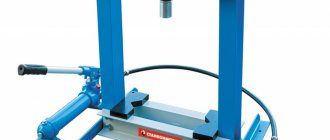
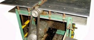
Pneumatic actuator based on membrane-spring pneumatic actuator
The same photo, from a different angle, is shown at the beginning of the article.
Above is a tube where the compressed air supply hose is connected. Next, the air pressure can be adjusted using a reducer and monitored with a pressure gauge.
Below is a solenoid coil and a valve that controls the air supply to the pneumatic drive (red container in the photo).
Next, the time is maintained, which is determined by the built-in timer (time relay). The timer delay time is set by the operator. This time depends on many factors (material, temperature, shape, design, etc.) and is usually selected experimentally.
After the delay time, the top plate rises, the cycle is completed.
Now you need to change the workpiece and repeat the cycle again.
Diagram of a pneumatic hot stamping press
The diagram is simple, I drew it directly next to the press, I publish it as is:
Electrical circuit of a pneumatic hot stamping press
Let's look at the diagram. When the Start 1 and Start 2 buttons are pressed, the voltage through the NC contact PB1 is supplied to power the time relay PB, which turns on, and as a result its NO contacts PB2 are closed.
Contact PB1 is not simple, but with a switching delay. In this case, this means that it opens after a delay determined by the PB timer. And during this time, voltage is applied to the air valve.
That's all for the electrical circuit.
The big minus is that there is no electrical safety at all. It's not about grounding. This applies to the circuit breaker, which is not at the input (a maximum of 6A is enough here) and the “Emergency stop” button for emergency raising of the piston. In addition, in case of direct or indirect touch, 50Hz shaking may occur.
Anyone interested in circuit breakers - here
, for emergency circuits -
here
.
For RCD functions – here
.
The circuit consists of two independent parts - a heating element heating circuit and an air valve control circuit. Let's look at them.
Turning on heating elements via a thermal controller
To power the heating elements, a temperature controller (thermostat) BERME REX C100 FK-02 VAN SSR is used. The last three letters - SSR - indicate that the controller output is intended to control a solid state relay (Solid State Relay). Anyone who wants to know what it is and what switching circuits it has - I recommend my article about solid-state relays
.
Thermoregulator, also known as a temperature controller, also known as a temperature controller, also known as a temperature control relay and a temperature controller with an output for a solid-state relay.
What's great about this temperature controller? It is strikingly different from old, classic temperature controllers in that when approaching a set point, it turns off and catches up with the temperature in pulses with variable duty cycle.
The closer the temperature is to the set value, the shorter the pulses. As a result, the temperature, depending on the settings, can be maintained with an accuracy of half a degree.
Smart thermal controller. I've seen these in places where special accuracy in setting the temperature is needed.
But the thermostats of the old system stupidly operate by hysteresis, as a result, depending on the design of the system and its inertia, the temperature varies within ±10...15 degrees.
The use of a “smart” temperature control relay would not be possible if a solid-state relay were not used as a switching element. A regular relay would have a hard time...
The feedback sensor gives feedback to the regulator, everything is clear here.
By the way, the accuracy of such a system greatly depends on the quality of the installation of heating elements and a temperature sensor. They must be installed so as to ensure reliable thermal contact with the heated plate, i.e.
the contact must have minimal thermal resistance.
In addition, it is important to install the sensor closer to the heating elements, especially if the mass of the heated metal is small and it cools intensively.
Temperature sensor and heating elements before installation in a metal plate
Solid State Relay – Fotek SSR-40 DA. DC voltage control 24V, switching – 220VAC.
Solid state relay – Fotek SSR-40 DA for turning on heating elements
Press pressure time delay
The delay during which the workpiece is “fried” is set using a TDM PB 2A time relay:
Time relay TDM PB2A for delay time adjustment
The time relay is a classic one, produced by many companies, from OMRON to Noname. There may be different operating modes that are switched. From the diagram shown on the relay body, it is clear that it has two switching contacts. Moreover, one is with a shutdown delay, the second is normal.
Regarding time relays, their operating principles and circuit design, I recommend my major work
on Zen. There, using the example of PVL, all theory and practice are considered.
I didn’t understand before why this relay needed a regular contact. Then it dawned on me - after all, it is needed for self-retaining, in order to fix it in the on state, like in a regular relay or contactor.
Appearance during installation:
DIY installation of a pneumatic press circuit
Addendum 1. Another diagram of a pneumatic press
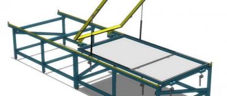
To complete the picture, I present a diagram that I created when restoring a press for gluing shoe parts. The operating algorithm is absolutely the same, the design is completely different.
Scheme of a rotary press for duplicating the toe cap of shoes
The materials used are coated with hot-melt adhesive. When pressed, the glue melts and the parts stick together.
The diagram is drawn clumsily, but that’s not the worst thing. The fact is that, instead of using the usual contacts of the time relay RL2, I additionally used the usual relay RL1.
Although, in justification, I can say that the pneumatic valve is powered through a conventional relay (RL1.2), which is several times cheaper and more accessible. Which is more far-sighted from the point of view of contact wear, and can be applied in the first scheme.
By the way, this machine has been making shoes all over the country for several years now.
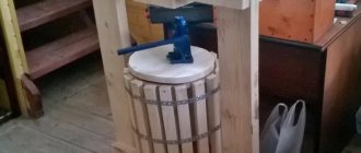
Appendix 2. Application in a bookbinding workshop
A reader of mine sent me a photo of what a similar press can do in a bookbinding shop where beautiful books are made to order.
The press is used (to be honest, this is currently the plan) to produce high-quality blind embossing. This is when no foil is placed under the cliche (of some color, there are many colors), but leather or leatherette is simply embossed with a hot cliche through a heat-resistant transparent film. The same leather (leatherette) darkens and becomes so-called. blind embossing. Foil stamping is also done.
Photo album, top cover and spine
My mother worked in a bookbinding shop, so I have an idea). True, a hand press was used there, and this is very labor-intensive.
mavickMV › Blog › Simple press for the garage with your own hands
Good day to all.
From time to time during work there is a need to press something in somewhere. But the problem is, I don’t have a press. A long time ago, my colleague and I did a small press. We worked with it for quite a long time, then when I left this box, this press was left to a colleague. Once again, when I need to press something in, I remember that I need to make myself a small press, but somehow everything was put off. Recently, overcoming laziness, my godfather and I decided to do press after all. We counted, estimated and sketched out a sketch.
The principle of the old press (which was in the old box) will be used as a basis - with a jack from below. Why such a project: 1. It has already been tested by me 2. Does not require additional financial and labor costs.
To begin with, I cleaned the old Lawn jack from dirt and dust. As it turned out, he didn’t really pump. I decided to try to make do with little expense - change the oil and at the same time wash the springs, valve balls and not yet climb into the cylinder due to the lack of a repair kit for the jack. This is the kind of disgusting thing that came off the jack
Judging by the appearance, it is a mixture of brake fluid and oil (pieces of dirt are visible in the photo). I also cleaned and lubricated the threaded part of the fittings and valve screws.
I fill in the oil, bleed it, and the jack works)))) Hurray! Bringing iron
The most important thing is the markup. To achieve the same dimensions, markings were carried out using a template made from a strip and two self-tapping screws.
Also, for the purpose of marking on metal, I used a caliper with sharpened jaws
My long-time assistant, a driller, helped me in making the press.
The legs were made from the corner of a 50
The jack is centered and fixed using bolts in the standard places of the jack
Next we install the movable table. The guide washers were welded in advance. The table turned out to be removable.
We weld the plate and centering washers on the moving table from below.
Well, the first test (there weren’t even springs on it yet) was the axle bearing
In place without dust and noise, the bearing is in place.
To make lowering the jack easier, I bought 4 springs
Here is a view of the press assembled.
I haven’t started painting yet, since the weather is not particularly conducive to painting, and as Kedr said with VWTS
“I will definitely not participate in the competition for the most beautiful abs. It won’t rust, at least in the next 10-15 years.” In principle, if you want, I’ll paint it
That's all for today, best regards,
Mavick MV
Source
Pneumatic press based on timer and temperature controller
Pneumatic press for perforation and hot stamping
In this article I will describe the design and electrical circuit of a pneumatic press for hot stamping on leather and cardboard, which I assembled with my own hands. Such pneumatic presses can be called differently, depending on the scope of application.
Unlike a hydraulic press, which is driven by a hydraulic pump, a pneumatic press develops pressure using compressed air produced by a compressor.
Based on the diagram and design described in the article, the following types of presses can work: perforation, hot stamping, various presses for molding and gluing parts.
Here, as an example, is my article about installing the Euroautomatika RT-820M temperature relay in a similar Turkish press.
In my case, the press is used in shoe production to hot-stamp the upper part of the shoe. As a result of the action of the press, a beautiful pattern or logo appears on the leather upper of shoes, shoes or boots. When installing a special mold and increasing the pressure, small holes can be drilled.
Agree, boots on a woman’s foot with a beautiful stylized flower on the top look much more impressive!
It is worth saying that a pneumatic press develops less pressure compared to a hydraulic one. But this is in the general case, it all depends on the specific model.
What and how to assemble a frame for the press?
The material for the frame, its structural strength and the method of assembly should be determined by the pressure that the jack is capable of delivering. For accurate calculations, it is important to understand in which direction the loads act during operation.
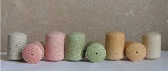
The base of the press is a rectangular U-shaped frame made of a channel or a paired steel angle. The main acting force is the resistance to compression, expressed in concentrated load. The main force is concentrated in the centers of the horizontal crossbars. The forces that stretch the vertical racks of the press and the phenomena of deformation in compressed parts can be completely neglected.
1 - upper thrust beam; 2 - bolts; 3 - jack 20 t; 4 — return springs; 5 - movable beam; 6 — locking pin; 7 - adjustable support beam; 8 - transverse beam; 9 - legs from corners
For installation with a compressive force of up to 5 tons, you can safely use the following to make a frame:
Channel dimensions 8P
Let us immediately make a reservation that we provide approximate data on rolled metal for a frame with an internal window no wider than 100 cm. By analogy, when using a jack with a force of up to 10 tons, the frame should be made from:
Channel dimensions 10P
If the required compression force reaches 15 tons or higher, then the frame should be made of:
Channel dimensions 14P
The above proposal for rolled metal products implies a tenfold safety margin, which completely eliminates exceeding the limit of elastic deformation and is normal for installations of this kind. All frame joints must be welded with solid double-sided seams and butt cut. If the connection is not made by welding, assembly with bolts or cotter pins is allowed. In this case, it is necessary to take into account the maximum permissible shear load.
With a bolted connection, the main load becomes dispersed and the compression force of the press must be divided by the number of bolts or pins. The destructive shear force of bolts made of the most common steel ST-3 is:
To ensure the required safety margin, each fastening element must experience a load five times less than the destructive load. For steel fingers, the force can be taken 10–15% higher than the specified values. If the required number of fasteners cannot be placed in a corner unit, you should increase the strength with gussets, for which it is preferable to use corner steel instead of sheet steel. The same applies to the welded frame structure, which also helps to avoid the use of excessively massive rolled steel.
In addition to the loaded upper part, the frame includes two racks with legs that provide the press with sufficient stability, and a cross beam that can be adjusted when processing parts of different sizes. The cross-section of the upper and lower beams must be equivalent, as well as the cross-section of their fastening elements. Everyone is free to implement the legs and support according to their own considerations; they do not experience work loads in addition to the own weight of the press. The only requirement is the presence of a bottom crossbar, which gives the structure additional rigidity.