From the outside it seems that welding is easy, you just need to learn how to hold a welding machine in your hands, and then you can weld anything. But in fact, this is a process that requires not only physical, but also intellectual effort, for example, in the correct organization of work. There are many parameters to be taken into account, including the weldability of steels.
Determination of weldability of steels
Before talking about welding steels, it is necessary to consider the concept of weldability. This is the name of the property that allows steel to withstand cooking without loss of quality. If a seam is obtained that meets GOST 2601 and the design features, this indicates good weldability of metals and alloys.
Metals have varying degrees of weldability, and alloys may contain elements that reduce or increase this ability. However, not only the type of metal affects, you also need to consider:
- amount of harmful impurities, their quantity;
- environmental conditions;
- the number of elements added to improve the properties of the alloy;
- part thickness;
- carbon content.
The welding mode can also play a role, since some metals require only certain types of joints. So the welder’s qualifications also have an indirect effect.
Methods for calculating carbon equivalent
The properties of steel generally depend on the presence of other metals in the alloy of iron and carbon. Knowing their content, using an empirical formula it is not difficult to calculate the value of the so-called carbon equivalent (Ce). This value allows you to determine what results to expect from welding metal products.
In Russia, to evaluate the welding characteristics of rolled products used to create structures, they use the formula approved by GOST GOST 27772-88:
Ge=C+(P/2)+(Cr/5)+(Mn/6)+(Cu/13)+(V/14)+(Si/24)+(Ni/40).
In Europe, the following relationship is used for calculations:
Se=C+(Mn/6)+(Cr+Mo+V)/5 + (Ni+Cu)/15.
In Japan, this method for determining carbon equivalent is:
Se=C+(Mo/4)+(Cr/5)+(Mn/6)+(Si/24)+(Ni/40),
where C, P, Cr, Mn, Cu, V, Si, Ni, Mo are the mass fractions (in %) of carbon, phosphorus, chromium, manganese, copper, vanadium, silicon, nickel, molybdenum.
Steel is considered not prone to cracking if the carbon equivalent value “C” is less than 0.45%. Otherwise, when there is already a possibility of their occurrence, the parts requiring connection must be heated before welding.
Classification of steels by weldability
To make it easier to determine the weldability of metals, steel grades were divided into 4 groups of weldability of parts. To present each classification, as well as its features, a weldability table has been created:
| Weldability class | Carbon concentration | Steel grades | Features of the welding process |
| I - Okay | Up to 0.25% | Carbon: VSt1–4, Steel 08, 10, 15, 20, 25. | There are no restrictions, depending on the density of the part, or temperature parameters. Therefore, you can select any welding mode. |
| Alloyed: 15G, 20G, 15Kh, 20Kh, 15KhM, 20KhGSA, 10KhSND, 10KhGSND, 15KhSND. | |||
| II - Satisfactory | From 0.25 to 0.35% | Carbon: VSt5, Steel 30, 35. | Calm weather, ambient temperature from +5 and above. The maximum permissible metal thickness is 20mm. |
| Alloyed: 12ХН2, 12ХН3А, 20ХН, 20ХН3А, 30Х, 30ХМ, 25ХГСА. | |||
| III - Limited | From 0.35 to 0.45% | Carbon: VSt6, Steel 40, 45. | Welding modes are selected from the permissible ones, their list is strictly limited. Before or during welding, the part is heated to 250ºC. |
| Alloyed: 35G, 40G, 45G, 40G2, 35Kh, 40Kh, 45Kh, 40KhMFA, 40KhN, 30KhGS, 30KhGSA, 35KhM, 20Kh2N4MA. | |||
| IV - Poor | Above 0.45% | Carbon: Steel 50, 55, 60, 65, 70, 75, 80, 85. | Welding with heating and mandatory post-processing. |
| Alloyed: 50G, 50G2, 50Х, 50ХН, 45ХН3МФА, 6ХС, 7Х3. |
Influence of alloying elements on weldability
In addition to carbon, alloying elements are also taken into account, and here they primarily affect weldability:
- Carbon. The higher the carbon concentration, the lower the ductility of the metal, which means its weldability decreases. This is due to the fact that during the oxidation of carbon, many gas pores are formed, due to which the seam will be susceptible to defects and rapid destruction. Therefore, it will be easiest to work with low-carbon steel, where the content of this element is below 0.25%.
- Silicon. Silicon is usually introduced as a deoxidizing agent, so in a concentration below 0.3% it does not interfere with high-quality welding. However, when this percentage increases to 0.5-1.5%, silicon becomes an alloying element. Because of it, refractory oxides appear, leading to the release of a large amount of slag, so the weldability of the part deteriorates.
- Phosphorus. The permissible amount of phosphorus is 0.08%; if it is higher, the ability to weld the part is reduced, as cold cracks appear.
- Nickel. Nickel is able to increase the strength of the part, as well as its ductility, so weldability improves. In low-alloy steels the nickel content is usually about 5%, and in high-alloy steels up to 35%.
- Molybdenum. In heat-resistant steels, the molybdenum concentration is usually kept at 0.2-0.8%, and in special steels used in high-temperature environments, molybdenum is not less than 2-3%. The strength of the part, as well as its ductility, increases, but the risk of defects in the seam remains.
- Chromium. A chromium concentration of up to 0.25% does not create problems for such a parameter as the weldability of metals. But as the amount of this element increases, the welding ability decreases, and a concentration above 1.1% is already considered bad for welding. Due to chromium, the chemical resistance of steel is reduced, which is why refractory oxides appear. Carbides released here during welding provoke corrosion.
- Tungsten. Tungsten reduces the weldability of the part and is highly oxidized.
- Niobium, titanium. Both elements improve the weldability of the part and are usually added to reduce the negative influence of other elements. For example, titanium or niobium in a content of 0.5-1% will react with carbon and interfere with the formation of carbide if the steel contains chromium. This will reduce metal corrosion.
- Nitrogen. This element is used to reduce the temperature of the weld pool. Its use provokes the release of iron nitrides, which increase the hardness of the metal, but reduce ductility, and therefore the ability to weld.
- Sulfur. The permissible sulfur content in steel is up to 0.06%. If this percentage is higher, hot cracks cannot be avoided.
- Copper. It has a positive effect on weldability, increases both strength and ductility, as well as toughness and even corrosion resistance. Usually the copper content does not exceed 0.8%, this is already enough for a positive effect.
Welding medium carbon steel
Carbon structural (machinery or construction) steels are those that contain up to approximately 2% carbon. First you need to know that the steel is filled:
- up to 0.25% are called low carbon;
- from 0.26% to 0.6 – medium carbon;
- from 0.6 to 2% - high-carbon.
And all of them do not have alloying elements. Anything higher than this content is called cast iron. Carbon determines the strength characteristics and directly affects the weldability of steels.
Composition, purpose and use
These materials are widely used in the national economy. Starting from the manufacture of simple nails to high-strength and especially critical structures.
The conversation here will be about working with steels saturated with medium amounts of carbon. These are materials where its share ranges from 0.25% to 0.45%. This percentage is the main difference from low-carbon steels. It imparts hardness to steel, but makes weldability worse. Used in shipbuilding and mechanical engineering.
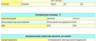
Since all carbon steels are also classified by quality, there are also manganese additives from 0.7% to 1%. In industry, medium-carbon steel is used in a normalized state, this is when the rolled product undergoes a certain heat treatment before the welding process.
In welded-cast and welded-forged structures, 35 steel or 40 steel are usually used.
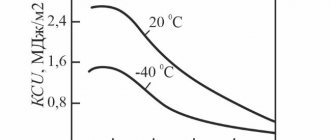
Characteristics of Medium Carbon Steel
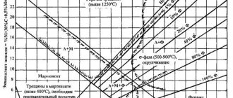
An unpleasant feature of these materials is the appearance of hardening structures in the weld, near the weld and the heat-affected zone (HAZ). These “bad” structures almost guarantee dangerous conditions for the “brittleness” of the connection.
This means that when choosing a steel grade, the manufacturer not only focuses on its strength characteristics, but also on how the welded joint will “behave” during preparation, during the manufacturing process, and what the mechanical properties of the joint will be after welding and during operation of the product.
Sometimes destruction occurs due to the fact that strong residual stresses appear in the connection and the ductility of the metal is greatly reduced. This is precisely the result of the wrong choice of material, welding method and welding technology.
Concept of weldability
Here you need to understand the “ability” of the material to withstand high-temperature conditions during a certain welding process without the appearance of sections of metal with “low plasticity” in the connection, which “provoke” the occurrence of cracks, or the fact that the connections are destroyed during operation. Simply put, this is the ability of metal parts to be joined by thermal action, without deteriorating the mechanical properties of the welded product.
Measures that must be taken when preparing this steel for welding:
- use only regulated base materials, for example: mild steel;
- welding methods will be used only those that guarantee the weld the required characteristics (welding with coated electrodes, submerged arc welding, in shielding gases);
- competently design welded structures (exclude contrasting transitions from one section to another, avoid “crowding” of seams in a small area of the product, whenever possible give priority to butt joints);
- special attention to assembly quality (minimize gaps and displacements, avoid tension in structures);
- try to use heat treatment, it relieves unnecessary internal stress.
Welding process and types
As mentioned above, a significant carbon content complicates the welding process.
To overcome the above difficulties and make the weld metal resistant to cracks in any fusion welding, it is necessary to reduce the level of carbon in the weld metal.
To do this, use welding materials with a low carbon content and reduce the amount of base metal in the joint. Simply, the edges are given the appropriate cutting shape.
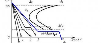
It is advisable to provide preheating to a temperature of 250-3000 C. Due to this, it is possible to almost eliminate the occurrence of hardening structures in the HAZ (heat-affected zone).
Mechanized and automatic welding
It is necessary to use such modes in which the penetration of the base metal would be minimal and the weld shape coefficient would be maximum. Increase the proportion of electrode metal in the weld. In semi-automatic operation, this is achieved by using small diameter wire and minimal current. In this case, it is better to work with direct current of straight polarity.
Alloying is also a good idea. To achieve this, it is enough to use wire with a reduced content of sulfur and phosphorus, with the addition of silicon and manganese. In automatic welding, alloying occurs due to flux.
Manual arc welding
For this welding, electrodes with a basic coating are used. They provide alloying, the seam becomes resistant to cracks. But to avoid brittle hardening structures in the HAZ, slow cooling of the product is desirable.
To do this, reduce the welding speed, preheat and use two or more extended arcs. The higher the carbon content, the higher the heating temperature during welding (accompanying heating) should be.
But all the same, when, with all the listed methods, it is completely impossible to impart the required ductility to the joint, hardening and tempering is used.
Electroslag method
This is a special welding method that uses a slag bath to heat the melting zone. Heating is carried out by electric current.
Here, thanks to the wide ability to change the shape coefficient of the bath and slow cooling, the conditions are created for creating a high-quality connection.
By feeding the wire at a speed not exceeding a critical value, high resistance against crystalline cracks is ensured.
Problems here may arise if the carbon content exceeds 0.33%. Then you need to use wire with manganese and silicon.
Carbon dioxide welding
The technology of this type is in many ways similar to manual arc welding or submerged arc welding. It is also based on reducing the percentage of base metal in the weld and ensuring favorable penetration. But it is rarely used in mass production.
It is important to remember that with any method of welding medium carbon steel, the most important point in the preparation and process is to impart the necessary ductility to the joint. And the way to ensure this plasticity is already selected based on the specific situation in which welding will take place.
Visual inspection of welded joints
Control of welded joints is an integral part of the entire technological welding process.
Visual inspection is one of the many methods to which all welded joints are subjected without exception. And not only. Work on visual inspection begins already at the stage of acceptance of basic and welding materials in welding production. But in this article only visual control will be considered. But first you need to understand the problems that it solves and what it is aimed at.
Defects in welded joints
Defects in welding production are defined as non-compliance with the norms and rules according to which the joint is made.
These “jambs” that arose during the welding process are divided into internal and external. External ones are revealed by visual inspection of the connection. Looking ahead, it should be clarified that visual control itself does not exist as a separate method. It always goes in conjunction with measurement.
In production this is called visual and measuring control. Well, in order to start measuring, it is necessary to visually identify defects, record them, and during measurement determine whether the identified inconsistencies are acceptable or not and how they will affect the operation of the product. Defects should be identified already at the stage of preparation for welding.
Since they directly affect the quality of the final welding product.
Defects during preparation for welding, the reasons for their occurrence and their impact on the quality of the connection
Inconsistencies in preparation and assembly lead to subsequent welding defects. For example: incorrect bevel angle of the edges, large or, on the contrary, small bluntness, axial displacement, mismatch of joining planes, increased gap and the geometry of the seam is unacceptably violated!
Unprocessed and uncleaned edges, damp surfaces or unheated electrodes, delaminations, incorrectly selected welding modes and pores, fistulas and lack of fusion along the seam are guaranteed!
Increased current strength, rapid movement of the electrode along the seam and undercuts smile at us!
If the arc is abruptly broken, there will definitely be an unwelded crater at the end of the seam.
All defects create a local stress concentration, reduce the useful cross-section of the seam, weakening the structure, and in some cases even spread further along the seam. For example, cracks and microcracks. It is clear that such a design will not withstand even a minimum service life.
Correct assembly is accompanied by external inspection and measurement using special verified devices, templates and standards. And the shape and dimensions of the seams are specified by technical specifications, which stipulate the number of passes and the depth of penetration.
A word about external defects
These outdoor “welding pests” include the following:
- sagging - flow of molten metal onto the base;
- undercuts - point or oblong grooves in the base metal, running along the edges of the seam;
- unwelded craters - a depression at the end of the weld when the arc suddenly breaks;
- burns - a through hole when welding the first layer of a seam;
- arson is the result of “striking” by the electrode when the arc is excited;
- cracks - rupture of metal along a seam or adjacent metal;
- pores - a round-shaped cavity;
- splashes - frozen drops on a connection;
- fistula - a defect in the form of a funnel in the seam.
It is all these defects that visual inspection is designed to identify and record.
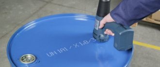
Visual inspection
• When carrying out welding work, preparatory actions are also subject to external inspection and often measurement.
The quality of the material is checked - the presence or absence of defects on the metal (burrs, dents, cleanliness of edges), the preparation of structural elements of the edges (correct cutting angle, gap, alignment), the quality and correctness of tack welding. Structures that were assembled in violation of technical specifications are rejected.
• During the welding process itself, the welder (he is the natural and first quality controller of the connection), in addition to monitoring the welding mode and the stability of the arc, observes how the beads are made when making multi-layer seams.
It is extremely important to control the quality of the initial pass (weld root). Because it is the first layer that “paints” the entire subsequent “picture” of the welded joint. Very often you even have to examine the root using a 4-7x magnifying glass.
• When visually inspecting finished products, a magnifying glass is also used. First of all, all those “welding jambs” that were mentioned above are identified. Most of them are unacceptable and must be corrected. Also, during visual inspection, great attention is paid to the shape of the seam, the correct “pattern” of the scales and the “overall picture” of the distribution of metal in the reinforcement of the seam.
Each seam, made in different “poses”, has its own appearance and shape.
When inspecting particularly critical products and structures (especially in the military and space industries), the appearance of the seams is often compared with specially made standards. The geometry is controlled using templates and measuring tools.
Visual control is quite informative and is a cheap and fast control method. And with careful observation of the welding process, the occurrence of many defects can be eliminated. Visual inspection is an inexpensive procedure and very effective in the technological process.
Conditions for visual and measuring control
To conduct a high-quality VIC, it is necessary to create certain conditions at any site. Whether it’s a high-tech production facility where they work in white coats and gloves, a welding shop or an installation site. They include:
- convenience of specialist approach;
- possibility of connecting local lighting 12 V;
- illumination should be at least 500 lux (500 lux);
- indoor walls, ceilings and tables should be painted in light colors;
- ensuring sufficient visibility for the specialist's eye. The surface is viewed at an angle of more than 300 to the plane and from a distance of no less than 600 mm;
- cleaning surfaces as required by regulatory documents;
- measures for safe control.
Only after a thorough visual inspection has been carried out and all inconsistencies have been corrected, the connections are subjected to other control methods, if required by the design documentation.