Types of springs and their designation in the drawings
There are quite a large number of different types of parts, and they are displayed differently on the document. The following have been distributed:
- Screw type is the most famous type, which is used today to create a wide variety of devices. An example is a car suspension. This design option is available in cylindrical and conical form. This drawing of a spring is very common and can be displayed in a simplified or other version.
- Torsion versions resemble the previous one, however, they can work simultaneously in torsion and bending. This type of part is used to create suspensions for heavy vehicles, measuring and many other instruments. On the document this option is depicted somewhat differently, it all depends on the specific variety.
- Spiral ones are used to create a wide variety of mechanisms, for example, wristwatches. The key feature is that a wire of a certain diameter is wound in a spiral. The distribution of a product can be associated with the possibility of accumulating and storing potential energy.
- Disc-shaped ones only partially resemble the classic version, but they are used quite often. They are represented by several disks that are located among themselves. The main advantage of this proposal is the insignificant deformation of the structure when exposed to large forces. Most often, poppets are used to create safety valves and
- Wave structures, which are characterized by their specific key features, can also be used. An example is that the coils have a strong curvature, due to which the dimensions of the device are significantly reduced.
Classification is also carried out according to the intended purpose of the product. The following main groups are distinguished:
- Sprains. In this case, adjacent rings are without clearance relative to each other.
- Compression. During manufacturing, a certain gap is left, which allows the last two rings to be brought closer to each other.
- Torsion and bending.
Many design options are displayed on the document taking into account established standards. At the same time, we should not forget that various parts are characterized by their specific performance characteristics.
SPRING DRAWINGS
Springs are used in technology to create certain forces in a given direction. In Fig. 545, 546. 549 show examples of the use of springs in various devices. Coil Compression Spring 5
(Fig. 545, a), pressed by the threaded bushing
3,
exerts
a force
2 4
to the end of the cylindrical protrusion of the body 1 and blocking the access of the working medium.
In Fig. 545, b shows a bending plate spring 1 holding the pawl 2
in a predetermined position that prevents the ratchet wheel
3
from turning counterclockwise.
In these cases, to move part 3
in the direction indicated by the arrow, it is necessary to apply a force exceeding the spring pressure.
The rules for making drawings of various springs are established by GOST 2.401-68 (ST SEV 285-76, ST SEV 1185-78). Let's look at the basic rules for drawing springs using the example of cylindrical helical compression springs, which are the most commonly used.
Springs in the drawings are drawn conditionally. In images of cylindrical helical springs, the sections of sinusoids into which the coils of the spring are projected are replaced by parallel straight lines tangent to the sections of the coils (Fig. 546, 548). In assembly drawings and general view drawings, it is allowed to depict a spring with sections of coils (Fig. 547). In this case, the contours of the parts located behind the spring are shown visible only up to the center lines of the sections of the turns.
If the spring has more than four turns, then at each end of the spring only one or two turns are depicted, not counting the support ones, and axial lines are drawn through the centers of the sections of the turns along the entire length of the spring (see Fig. 545, a).
To obtain flat supporting surfaces on the spring, the outermost coils of the spring are pressed (about three-quarters of a turn and ground. The pressed coils of the spring are not considered working. Therefore, the total number of coils n1 is
equal to
+1.5
. Fig. 548 shows an image of the spring , in which 3/4 of the turns are pressed and ground. Here one of the support turns and two working turns are shown. The construction begins by drawing axial lines passing through the centers of the sections of the spring turns (Fig. 548,
a).
Then a circle is drawn on the left axial line , the diameter
d
of which is equal to the diameter of the wire from which the spring is made. The circle in this case touches the horizontal line on which the spring rests. Next, a semicircle is drawn from the center located at the intersection of the right axis with the same horizontal line. To construct each subsequent turn of the spring on the left sections of turns are constructed at a step distance.On the right, each section of a turn will be located opposite the middle of the distance between the turns constructed on the left.
By drawing tangents to the circle, we obtain a cross-sectional image of the spring, i.e., an image of the coils lying behind the plane passing through the axis of the spring. To depict the front halves of the turns, tangents to the circles are also drawn, but with an elevation to the right. To construct the front quarter of the support turn, the tangent to the semicircle is drawn so that it simultaneously touches the left circle in its lower part (Fig. 548.6).
If in the drawing the cross-sectional diameter of the wire or the thickness of the workpiece from which the spring is made is equal to or less than 2 mm, then the spring is depicted with lines 0.6 thick. 1.5 mm (Fig. 549).
In working drawings, images of helical springs are positioned so that the axis has a horizontal position. Springs are shown with right-hand winding, and the actual winding direction is indicated in the technical requirements. For springs with controlled force parameters, a diagram of the mechanical characteristics of the spring is drawn in the drawing, showing the relationship between the load on the spring ( p1
,
р2, р3
) and its deformation
(H, Н2
and
Нз)
. An example of a working drawing of a spring is shown in Fig. 550. A diagram is not drawn on educational drawings.
Length L
the deployed spring is determined by
formula
, where
Dcp
is the average diameter of the spring. Which spring diameter should be indicated in the technical requirements (rod diameter Dc or sleeve diameter Dr) is decided depending on which of these dimensions is controlled.
Displaying the technical parameters of the spring in the drawing
Designation can be made on a drawing using a variety of methods. An important point is that the applied standards are specified in GOST 2.401-68. The applied scheme and established standards determine the following points:
- All product types must be displayed in exempt condition only. It is characterized by the fact that there is no pressure on the wire from the external environment.
- It is worth considering that for all products an additional note is created, which indicates all the main technological features.
There are quite a large number of different parameters that are important. An example is the number of turns, stiffness coefficient and much more.
Compression spring drawing
Executions designed for compression have become quite widespread. They are used to create a wide variety of mechanisms, and at the same time are characterized by their own specific features. Considering the drawing of a compression spring, we note the following points:
- In the case where the part has more than 4 turns, only 1-2 turns are drawn on both sides.
- Due to the large length, all rings are not shown. However, the latter are displayed as a dashed line and an axial line is created.
- If a wire is used in the manufacture of a product, which has a thickness of no more than 2 mm, then it is displayed by lines with a thickness of 0.6-1.5 mm.
Do not forget that all dimensions must be displayed on the document. The most important are:
- Diameter of the wire used. It can vary over a fairly large range.
- Ring spacing. Another determining parameter that must be taken into account.
- Average diameter, as well as internal and external. They determine the main dimensions.
- Free length of the product. The free state is considered to be when there is no load on the part.
In general, we can say that the task of displaying the part is quite difficult to perform.
EXECUTION OF WORKING DRAWINGS OF SPRINGS
2.1. Helical compression and extension springs should be shown with the winding direction to the right. The left winding direction must be specified in the technical requirements.
Torsion springs must be shown with the required winding direction.
(Changed edition, Amendment No. 2).
2.2. On the working drawing of a spring with controlled force parameters, a test diagram is placed, which shows the dependence of load on deformation or deformation on load. If the specified parameter is length (height) or deformation (linear or angular), then indicate the maximum deviations of the load - force or moment (Fig. 1-3, 5-18). If the specified parameter is a load, then indicate the maximum deviations of length (height) or deformation (Fig. 4).
If to characterize a spring it is enough to specify only one initial and dependent parameter (for example, and ; and ), then it is permissible not to show the diagram in the drawing, but to indicate these parameters in the technical requirements.
(Changed edition, Amendment No. 3).
2.3. For a spiral flat spring with controlled force parameters, in addition to the diagram, the drawing includes a diagram of the spring fastening indicating the dimensions of the shaft and drum (Fig. 15).
2.4. For a package of disc springs with controlled power parameters, the drawing shows, in addition to the diagram, a diagram of the arrangement of the springs in the package.
If the mechanism uses one disc spring with controlled force parameters, then the diagram can be given for one spring.
2.5. For a leaf spring with controlled force parameters, in addition to the diagram, the drawing shows a diagram of the spring fastening and indicates the dimensions from the point of application of the load to the place of fastening (Fig. 18).
2.6. If two loads are controlled on a spring, then the maximum deviations of the length (height) of the spring are not set (Fig. 2, 3, 5-8, 11).
2.8. In the drawing, if necessary, indicate as reference dimensions the magnitude of the force, moment, axial and angular deformation of the spring, the length of the spring at maximum load, the maximum value of the height of the disk spring package or the maximum value of the deformation of the disk spring package, the angle between the hooks, the number of revolutions of the spiral spring drum , spring pitch, shear modulus, elastic modulus, maximum torsional and bending stress.
Tension spring drawing
A part that is intended to be stretched is characterized by its own specific characteristics. It also occurs quite often, but special properties are also reflected in the schematic display. The extension springs under consideration are depicted as follows:
- In the free state, all the turns are close together, there is no gap. This point largely determines the difficulties in displaying the product.
- The pitch in the case under consideration is equal to the width of the wire.
- All turns, except the outer ones, which are intended for engagement, are in operation during operation.
- The document shows the toe rings in expanded form. They are an important part of the stretching mechanism and are designed for fixation.
Read also: Gel flux for soldering
As in the previous case, in this case the main dimensions except the step are displayed. Examples include the outer and inner diameters, as well as the free length.
FAQ
Select a topic FAQ- Compression springs
- Extension springs
- Torsion springs
- Conical springs
- Electronic commerce
Compression Springs
What about wire diameter tolerances?
The results list shows the wire diameter for each spring. Permissible deviations are indicated in accordance with wire production standards (for example: DIN, EN, etc.). When winding, the diameter of the wire may vary slightly.
What about perpendicularity tolerances?
The permissible deviation from perpendicularity is less than 3° for the spring in the free state.
Winding direction?
Compression springs have a right winding direction.
Finishing treatment?
Steel compression springs are lubricated after manufacture to prevent corrosion. For better results, you can use galvanized wire (salt fog resistance: 96 hours) or stainless steel wire (eg AISI 302, salt fog resistance 200 hours).
What can we say about magnetic properties?
Stainless steel has very low magnetic properties compared to steel wire.
Linearity of loads?
For constant pitch cylindrical compression springs, the spring constant (spring pressure in N/mm) is linear and ranges between 15% and 85% of the full stroke. Full stroke = Free length - Compressed length.
Is it possible to overload the spring?
Extreme loads that cause full compression of the spring should be avoided as much as possible, since there is a risk of gradual loss of its mechanical properties. For example: loss of free length.
When is spring deflection possible?
Spring deflection occurs when the free length of the spring becomes 4 times the outer diameter of the spring, which can cause compression instability and results in bias toward the center coils.
Extension springs
What about wire diameter tolerances?
The results list shows the wire diameter for each spring. Permissible deviations are indicated in accordance with wire production standards (for example: DIN, EN, etc.). When coiled, the diameter of the wire may vary slightly.*
Winding direction?
The extension springs are right-hand wound.
Loop type?
Stretch loops with English loops have closed loops that form a ring. Both loops are in the same plane. Tension springs with German loops are manufactured in two versions: with loops positioned at an angle of 0 degrees and 90 degrees.
What is the difference between English and German loops?
Extension springs with English loops are used when the loops must be completely closed at the ends of the spring. As for German hinges, they have greater fatigue strength compared to English hinges.
Finishing treatment?
Steel compression springs are lubricated after manufacture to prevent corrosion. For better results, you can use galvanized wire (salt fog resistance: 96 hours) or stainless steel wire (eg AISI 302, salt fog resistance 200 hours).
What can we say about magnetic properties?
Stainless steel has very low magnetic properties compared to steel wire.
Is it possible to overload the spring?
Extreme loads that cause the spring to stretch close to its maximum should be avoided as much as possible, since there is a risk of gradual loss of its mechanical properties. For example: loss of free length.
Torsion springs
What about wire diameter tolerances?
The results list shows the wire diameter for each spring. Permissible deviations are indicated in accordance with wire production standards (for example: DIN, EN, etc.). When coiled, the diameter of the wire may vary slightly.*
Loose shoulder position?
The free position of the arms of torsion springs is of 4 types: at an angle of 0, 90, 180 or 270 arms.
What is torque?
Torque is the result of the force of the load multiplied by the arm of its application.
The unit of measurement is millimeter * newton
.
Not to be confused with force measured in newtons. The following formula demonstrates the difference between torque and force: M = F*Ls
, where Ls is the length of the arms, measured from the centerline of the coil to the edge of the spring arm.
What is the winding direction?
The right winding direction ensures a counterclockwise torsion movement. The left winding direction ensures a clockwise circling movement. Each article provides both types of winding.
What can you say about the ends?
The springs end with ends having a straight wire cross-section.
Conical springs
What is the fundamental difference between conical and cylindrical compression springs?
Conical compression springs can be used for the same purposes as coil compression springs. The advantage of conical compression springs is their very short compressed length.
Is the step permanent?
For all Vanel conical springs, the pitch is not constant, but the elasticity coefficient is unchanged.
Electronic commerce
What type of industrial springs can I buy in the company’s online store?
compression springs, extension springs, torsion springs, conical springs. We also offer special springs. If the catalog does not contain the spring you need, we will make it to order.
I don't have a user account. Can I order springs?
No. If you are not logged in, you can only search for industrial springs in our catalog, but you cannot add any springs to your cart.
I would like to know if all fields on the registration form must be completed?
No.
No, it is not necessary to fill in the following fields: Contact Person
,
Fax
,
Web Page
and
Address 2
.
Can I change my personal information in the future?
Of course, after registration you can edit your personal data and change them at any time.
How can I find the industrial spring model I'm interested in?
Generally, there are two search methods. Firstly, you can select the type of spring you are interested in in the menu on the left or click on the image of the spring. You will automatically be taken to the appropriate page, which contains detailed information about the technical parameters of industrial springs. On the same page you will find two buttons that allow you to perform a simple or advanced search. The second way to find the appropriate spring is to enter the product article in a special field located under the menu or at the search node level.
what is the difference between simple and advanced search?
As a rule, the fundamental difference lies in the number of parameters specified to search for the desired spring model. A simple search focuses on the basic parameters of springs. This method is very fast, but produces less accurate results than advanced search.
Do I need to fill out all search fields?
No. However, remember that the more parameters you specify, the more accurate the results will be.
Why do you call your search engine “the most modern and simplest”?
The biggest advantage of our search engine is its extraordinary simplicity and intuitive use.
On the other hand, the system is very efficient and performs a very fast search for the required spring. Moreover, we have prepared a special “Help”
. This is a program that explains step by step how to use our search engine to find the appropriate spring as quickly as possible.
How can I order more springs of the same type?
You must indicate the number of springs in the
"Quantity"
.
You must remember that you cannot order more springs of the same type than indicated in the "In stock"
.
When you specify a new number of springs, click on the “Change quantity of products”
.
I have added a spring to my cart and would like to make other purchases. What should I do?
There are two possibilities.
You can use the standard menu located on the left side of the site or click on the “Return to Shopping”
provided in the shopping cart.
I would like to know if it is possible to add different types of industrial springs to my cart?
Of course, you can add all available springs into one basket, namely: compression springs, extension springs, torsion springs and conical springs in different quantities and different configurations.
I found interesting models of industrial springs, but had to log out without ordering them. Should I look for them again the next time I visit the site?
No, but please do not forget to save your cart.
Its contents will be available every time you log into your account. To save your cart, enter its name in the appropriate field, then click on the “Save”
. Moreover, you can store several baskets containing springs of different configurations.
I did not find the spring model I was interested in. Can you help me?
We invite you to visit the
Special Springs
of our store.
You can send us a price request from this page. We can produce special springs to order according to your needs. We currently offer the following types of specialty springs: Shaped Springs, Flat Springs, Electric Coils, Special Torsion Springs, Special Extension Springs with Custom Loops, Special Compression Springs, and Extra Long Compression and Extension Springs.
Torsion spring drawing
As previously noted, the design option designed for torsion is quite difficult to display. The key points are the following:
- Two types are often depicted.
- If a part has a large number of turns, then a certain part is not displayed.
- The main dimensions can be called the diameter of the wire used in manufacturing, the diameter of the created rings and the central bend.
The considered version of torsion is very common. It is used in the manufacture of various mechanisms.
Wire product drawing
All types of mechanisms are made using wire. That is why the following information is indicated when displayed:
- Diameter.
- Length.
- Type of material used in manufacturing.
Some details cannot be displayed in a simplified form. This is why quite a lot of difficulties arise when creating a document.
How to draw a spring?
There is practically no single and universal algorithm for displaying the product in question. That is why you can draw a spring using a variety of methods. In addition, there is a unified design documentation ESKD drawing. The algorithm of actions is as follows:
- The axis is displayed. Established standards determine that the axis is displayed as a dash-dotted line.
- The main parameters are determined. An example is the pitch between individual turns, as well as the diameter of the wire used.
- Circles are displayed with a certain step. To do this, axes are drawn, the distance of which is determined by the pitch, as well as the diameter of the turns. Initially, the circles are drawn with a thin line.
- The circles are connected to each other by lines. Due to this, the main part is formed. Where the turns intersect, the lines are drawn with strokes.
- The next step is to break the central part in the case of a large length of the part in the free state.
- Next, the main dimensions are applied. As previously noted, this is the free length, the average, minimum and maximum diameter of the turns, the diameter of the wire used in manufacturing, the pitch and some other parameters. It is worth considering that if there is not enough free space to display all sizes, they are entered into a special table.
The depiction of springs in the drawings involves the creation of a fairly large number of auxiliary lines, which are required for the precise positioning of the main elements. The cable suspension of some other mechanisms is also displayed in a similar way.
In conclusion, we note that today you can draw a sketch manually or using special programs. More often than not, special software is used recently. This is due to the fact that the electronic form of the product is the easiest to transfer and correct. In addition, when using the program, you can increase the accuracy of the finished result and speed up the process itself.
If you find an error, please select a piece of text and press Ctrl+Enter.
Spring drawings are made according to [8.1]. Helical compression and extension springs are shown with the winding direction to the right. The left winding direction is indicated in the technical requirements.
Torsion springs are shown with the required winding direction. The compressed ends of the coils of compression springs are depicted as shown in Fig. 8.18.
The following conventions are established for the spring parameters:
N
— height (length) of the spring in a free state;
GG
o is the height of the spring between the hooks;
L is the height of the disc spring in the free state;
I,, Нъ Н3
— spring height under load;
F, F2, F3
— axial deformation (deflection) of the spring;
/3 - maximum deformation of the disc spring;
3 /A circle (b); a - pressed to E / A
coil and ground
3/4
of the circle
DC
— diameter of the control rod;
L
— length of the deployed spring;
L
— length of the leaf spring in the free state;
X
— the gap between the end of the support turn and the adjacent working turn;
xx,
t2, t3 - tangential stress during torsion; c,, a2, a3 - normal bending stress;
Rn
— force of interturn pressure; s—thickness (height) of the section; sK is the thickness of the end of the support turn;
ctlt а* а3 — angle between the torsion spring hooks under load; / - number of cores in the cable;
l is the number of working turns or disc springs in the package; l, - the total number of turns or the number of turns of the spiral spring in a free state;
Read also: Master station wagon 2500e owner reviews
Vi* V2* V3 — number of revolutions of the coil spring drum; t
— spring pitch;
IN
— section width;
b is the width of the supporting plane of the disc spring. Note. Index 1 is used to indicate values corresponding to preliminary deformation, index 2 - working deformation, index 3 - maximum deformation of the spring.
Examples of drawings of springs are shown in Fig. 8.19. 8.33.
Rice. 8.20. Compression spring with ends pressed one turn and support surfaces ground 3/4 of the circle
Rice. 8.19. Compression spring with ends pre-tensioned by 3/4 turns and supporting surfaces ground by 3/4 of the circle
On the working drawing of a spring with controlled force parameters, a test diagram is placed, which shows the dependence of load on deformation or deformation on load. If the specified parameter is height or deformation (linear or angular), then indicate the maximum deviations of the load - force or moment (see Fig. 8.19, 8.21, 8.33). If the specified parameter is a load, then the maximum deviations of height or deformation are indicated (see Fig. 8.20).
For a tension spring with interturn pressure, force values Рн
(see Fig. 8.26).
If to characterize a spring it is sufficient to specify only one initial and dependent parameter (for example, P2
and F2, 3/4 turns ends and
support surfaces 3/l
For a spiral flat spring with controlled force parameters, in addition to the diagram, the drawing includes a diagram of the spring fastening indicating the dimensions of the shaft and drum (see Fig. 8.30).
Rice. 8.22. Three-core compression spring with ends pressed 3/4 turns
The winding direction of the spring is counterclockwise. The direction of laying the cable is clockwise.
• Dimensions and parameters for reference.
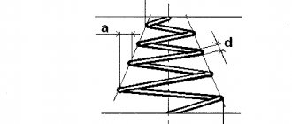
Rice. 8.23. Conical compression spring made of round wire with a preload of 3/A
coil ends and
support surfaces 3/4
Rice. 8.24. Conical (telescopic) compression spring made from a rectangular cross-section with ground surfaces 3 /4
circles with supporting surfaces
Rice. 8.25. Tension spring made of round wire with hooks located in the same plane
Rice. 8.26. Tension spring with interturn pressure made of round wire with hooks located at an angle of 90°
For a package of disc springs with controlled power parameters, the drawing shows, in addition to the diagram, a diagram of the arrangement of the springs in the package (see Fig. 8.31, 8.32).
Rice. 8.27. Torsion spring made of round wire with straight ends located at an angle of 90°
If the mechanism uses one disc spring with controlled force parameters, then the diagram can be given for one spring.
For a leaf spring with controlled force parameters, in addition to the diagram in the drawing, a diagram of the spring fastening is given and the dimensions from the point of application of the load to the place of fastening are indicated (see Fig. 8.33).
Rice. 8.28. Torsion spring with straight ends located along the axis of the spring
If two loads are controlled on a spring, then maximum height (length) deviations are not set (see Fig. 8.19, 8.21, 8.24). If only one load is controlled or a diagram is not shown in the drawing, then the maximum deviations of the height (length) of the spring in the free state are indicated.
Rice. 8.29. Spiral spring size restrictions only -
from a rectangular blank with an internal or external cross-section with bent hooks equal to the diameter of the helical spring
Rice. 8.30. Flat spiral spring made from a rectangular blank with fastening to the shaft and drum
Rice. 8.31. Belleville spring with inclined edges
Rice. 8.32. A disc spring with straight edges in the drawing indicates one of the requirements for the rod or sleeve (Dc or Dr).
You can indicate on the drawing the maximum deviations of the spring diameter, then the requirement for control of the rod and sleeve is not placed on the drawing (see Fig. 8.20, 8.23. 8.26).
The drawing indicates: reference values of force P3, moment M3, axial spring deformation F3 and angular cp3, angle between spring hooks a3, number of revolutions of the spiral spring drum y3, spring height under load H3, shear modulus G, elastic modulus E ,
maximum stress during torsion t3 and bending a3.
Rice. 8.33. Leaf bending spring
In the drawing of a spring of a standardized design, the values of G, E,
t3, a3 can be omitted, but the technical requirements of the drawing provide a reference to a standardized spring.
The hardness value is indicated, if necessary, only on the drawing of the spring subjected to heat treatment after winding.
The range of spring material, which completely determines the dimensions and maximum deviation of the cross section, is indicated in the Material
title block of the drawing.
Read also: Abrasive stones for sharpening knives
When it is necessary to take into account changes in the shape and dimensions of the section, the drawing shows the shape and dimensions of the section of the coil of the finished spring (see Fig. 8.21, 8.22).
Table 8.1. Classification and standards for the main parameters of coils of cylindrical helical tension and compression springs made of round steel
Spring class and category
Spring force at maximum deformation, N
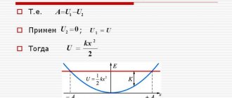
The functions performed by springs are very diverse. They are used: in brakes, friction gears; for accumulating energy with the subsequent use of a spring as a motor (for example, clockwork); for shock absorption and vibration absorption (springs, buffers); for return movements of valves, cam mechanisms, etc.
In all these cases, the main property of a spring is used - after the end of the action of an external force on it, it returns to its original shape under the influence of internal elastic forces.
According to the type of loading, springs are divided into compression, tension, torsion and bending springs; in shape (Fig. 8.112, a-d) - into cylindrical screw (a, b) and conical (c, d), compression with different cross-sectional shapes of the turn; cylindrical tension (d); torsion (e); spiral (w); leafy (h); disc-shaped (and) etc., see GOST 2.401-68* (ST SEV 285-76.and 1185-78).
The turns of a helical cylindrical or conical spring are depicted by straight lines tangent to the corresponding sections of the contour (Fig. 8.112, a, c, e, f). It is allowed to depict only sections of turns in a section. If the diameter of the wire or the thickness of the material section on the drawing is 2 mm or less, then the spring is depicted with lines 0.5 thick. 1.4 mm (Fig. 8.113).
Springs are shown with right-hand winding, indicating the direction of winding in the TT.
When drawing helical springs with a number of turns of more than four, show one or two turns at each end of the spring, except for the support ones (Fig. 8.112), drawing axial lines through the centers of the sections of the turns along the entire length of the spring. Springs are depicted with an axis parallel to the main inscription of the drawing.
As a rule, a test diagram showing the dependence of deformation (tension, compression) on force F1 is placed on the working drawing - with preliminary deformation in N (kgf), F2, which provides the required working deformations, and F3, which causes maximum deformation (Fig. 8.114). Deformations indicate either a change in the height of the spring (Fig. 8.115, where l is the height of the spring at preliminary deformation, l2 is the same at working and l/3 at maximum deformation; l0 is the height of the spring in the free state), or elongation under the corresponding load (Fig. 8.116), values l2 and l3; l0 is the length of the spring without hooks in the free state;
The technical requirements located under the image of the spring indicate:
- spring standard number (if available);
- winding direction;
- n is the number of working turns (for tension springs, all turns are working, except for the hooks);
- the total number of turns A|, usually equal to n+1.5. 2 (see Fig. 8.115);
- hardness HRCE (if necessary, not indicated on training drawings); 6) length L of the deployed spring, calculated by the formula: L=3.2D0n1 (excluding hooks), where D is the average diameter of the spring;
- dimensions for reference;
- other technical requirements (they are not included in training drawings).
In critical cases, indicate the diameters of the control sleeve (Dg) and rod (Dc) to control the curvature of the spring axis.
To form support turns, either a whole turn is pressed (Fig. 8.117, a, 6), or 3/4 (Fig. 8.117, c), and, as a rule, in cases b, c they are ground to 3/4 of the arc of a circle to prevent misalignment of the spring axis (see Fig. 8.115). The bending radius of the hooks is taken equal to D—2d.
Depending on the operating conditions, the springs (required spring force, temperature difference, etc.) are made from wire of class I (high strength) or classes II and IIA (less strong), produced according to GOST 9389-75* (-60. + 120° C), from cheaper wire, from steel grade 65G, from steel grade 50HFA, used for the manufacture of class I springs under conditions of temperature differences from -180 to +250 ° C and the required force P3 = 140. 6000 N (14.600 kgf), from spring bronze wire, for example BrOTs4-3, and other materials.
An example of an entry in column 3 (material) of the main inscription: Wire 4-1 GOST 9389-75, where 4 is the diameter of the first class wire made of grade 45 steel according to GOST 1050-88.
For rules for drawing up drawings of conical, spiral, leaf and other springs, see GOST 2.401-68* (ST SEV 285-76 and 1185-76).
Rules for drawing springs
12. Torsion spring with straight ends located along the axis of the spring
13. Flat spiral spring with bent hooks
13a. Tape spring
14. Disc spring with inclined edges
15. Disc spring with straight edges
16. Package with a sequential diagram for assembling disc springs
17. Package with a parallel circuit for assembling disc springs
18. Leaf bending spring
18a. Cylindrical torsion bar
18b. Torsion bar
19. Multilayer lamellar bending spring (spring), tightened with a clamp
19a. Multilayer lamellar bending spring (spring)
19b. Multilayer lamellar bending spring (spring) with lugs
(Changed edition, Amendment No. 3, 4).
1.2. When drawing a helical spring with a number of turns of more than four, 1-2 turns are shown at each end of the spring, except for the support ones. The remaining turns are not depicted, but axial lines are drawn through the centers of the turns' sections along the entire length of the spring (table, paragraphs 1-6 and 8-11).
1.3. Springs in the drawings are shown with right-hand winding. If the directions of the end moments are specified, it is possible to depict springs with the required winding direction.
1.4. When drawing a package of disc springs with the number of springs more than four, 2-3 springs are depicted at each end, and the outline of the conditionally unshown part of the package is drawn with solid thin lines (table, paragraph 16).
1.5. If the diameters of the wire and cable or the thickness of the material section in the drawing are 2 mm or less, then the spring is depicted with lines 0.6-1.5 mm thick (table, paragraphs 1-18); a multilayer leaf spring of the spring type is depicted along the outer contour of the package (table, item 19).