Development of a right circular cone
The development of the lateral surface of a right circular cone is a circular sector, the radius of which is equal to the length of the generatrix of the conical surface l, and the central angle φ is determined by the formula φ=360*R/l, where R is the radius of the circle of the base of the cone.
In a number of problems of descriptive geometry, the preferred solution is to approximate (replace) a cone with a pyramid inscribed in it and construct an approximate development, on which it is convenient to draw lines lying on the conical surface.
Construction algorithm
- We fit a polygonal pyramid into a conical surface. The more lateral faces an inscribed pyramid has, the more accurate the correspondence between the actual and approximate development.
- We construct the development of the lateral surface of the pyramid using the triangle method. We connect the points belonging to the base of the cone with a smooth curve.
Example
In the figure below, a regular hexagonal pyramid SABCDEF is inscribed in a right circular cone, and the approximate development of its lateral surface consists of six isosceles triangles - the faces of the pyramid.
Consider the triangle S0A0B0. The lengths of its sides S0A0 and S0B0 are equal to the generatrix l of the conical surface. The value A0B0 corresponds to the length A'B'. To construct a triangle S0A0B0 in an arbitrary place in the drawing, lay off the segment S0A0=l, after which from the points S0 and A0 we draw circles of radius S0B0=l and A0B0= A'B', respectively. We connect the intersection point of the circles B0 with the points A0 and S0.
We construct the faces S0B0C0, S0C0D0, S0D0E0, S0E0F0, S0F0A0 of the pyramid SABCDEF similarly to the triangle S0A0B0.
Points A, B, C, D, E and F, lying at the base of the cone, are connected by a smooth curve - an arc of a circle, the radius of which is equal to l.
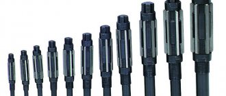
Types of metal reamers
Varieties:
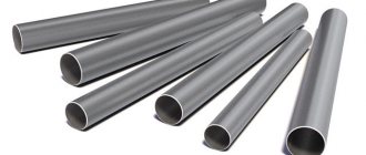
- Mounted. A tube with sharp teeth on the outside. In the center there is a functional hole for attaching the shank. Most often used for working on drilling machines.
- One piece. Monolithic equipment. Can be made of tool or high-speed steel.
- Unregulated. It has a fixed diameter that cannot be changed with additional nozzles.
- Combined. Combines two tools. It has two working surfaces. Thanks to this, the functionality is expanded.
- Adjustable. Universal equipment, the maximum diameter of which is 50 mm. This is a special tool whose working part diameter can be adjusted.
- Cylindrical. Standard equipment used for machining ordinary holes.
- Awl. Suitable for machining holes in soft metals. There may be two types. Collapsible - a hand tool consisting of two parts (point and handle). If necessary, the diameter of the holes can be expanded to 14 mm. The tetrahedral awl is the second type of hand tool. It differs from the standard awl by its small-diameter tetrahedral tip.
- Conical. Suitable for machining conical, standard holes. The shape of this equipment is similar to an elongated cone with a sawn-off top.
- Manual. Accessories for installation in gates. Has a square shank. The maximum diameter is 50 mm. The larger the diameter, the more difficult it is to work with such a tool.
- Stepped. Similar to a conical reamer, but has several steps with projections along the entire length of the cone.
- Machine. Equipment for working with power tools, drilling machines. May have a cylindrical or tapered shank.
In the technical literature you can find a classification based on other criteria - the shape of the grooves (helical or straight), the number of cutting teeth (from 6 to 16), and the material.
The reamer is made of high-speed or tool alloy steel. Popular types are 9ХС, Р9, Р18.
Inclined cone development
Let us consider the procedure for constructing a scan of the lateral surface of an inclined cone using the approximation (approximation) method.
Algorithm
- We inscribe the hexagon 123456 into the circle of the base of the cone. We connect points 1, 2, 3, 4, 5 and 6 with the vertex S. The pyramid S123456, constructed in this way, with a certain degree of approximation is a replacement for the conical surface and is used as such in further constructions.
- We determine the natural values of the edges of the pyramid using the method of rotation around the projecting straight line: in the example, the i axis is used, perpendicular to the horizontal projection plane and passing through the vertex S. Thus, as a result of rotation of the edge S5, its new horizontal projection S'5'1 takes a position at which it is parallel to the frontal plane π2. Accordingly, S''5''1 is the natural value of S5.
- We construct a development of the lateral surface of the pyramid S123456, consisting of six triangles: S01060, S06050, S05040, S04030, S03020, S02010. The construction of each triangle is carried out on three sides. For example, △S01060 has length S010=S''1''0, S060=S''6''1, 1060=1'6'.
The degree to which the approximate development corresponds to the actual one depends on the number of faces of the inscribed pyramid. The number of faces is chosen based on the ease of reading the drawing, the requirements for its accuracy, the presence of characteristic points and lines that need to be transferred to the development.
Transferring a line from the surface of a cone to a development
Line n lying on the surface of the cone is formed as a result of its intersection with a certain plane (figure below). Let's consider the algorithm for constructing line n on a scan.
Algorithm
- We find the projections of points A, B and C at which line n intersects the edges of the pyramid S123456 inscribed in the cone.
- We determine the natural size of the segments SA, SB, SC by rotating around the projecting straight line. In the example under consideration, SA=S''A'', SB=S''B''1, SC=S''C''1.
- We find the position of points A0, B0, C0 on the corresponding edges of the pyramid, plotting on the scan the segments S0A0=S''A'', S0B0=S''B''1, S0C0=S''C''1.
- We connect points A0, B0, C0 with a smooth line.
Do-it-yourself file reamer
In this article, the author of the YouTube channel “TOKARKA” will tell you about making an interesting tool - a reamer. It is useful for manually increasing the diameter of holes.
Materials. — Old triangular file — Wooden handle — Brass round timber — M12 hairpin — Epoxy glue — Machine oil — Parquet varnish — Sandpaper — Flux, solder, GOI paste. Tools used by the author. — Belt sander — Grinder, grinding and cutting discs — Soldering iron — Sharpening and lathe — Small forge — Gas torch — Vise, awl. Manufacturing process. So, the master found an old triangular file. First, he grinds its edges with a grinding disc.
He finishes the surfaces on a belt sander. This is a rather lengthy process; it is necessary to cool the workpiece in water.
Now the workpiece needs to be hardened. The author heats it in a simple furnace until it turns crimson and cools it in oil. After this, you can temper the metal.
By the way, in this article you can familiarize yourself with the method of making a simple forge.
Next, the craftsman grinds down the back of the file so that a handle can be attached to it. The standard shank can be cut off, and the main part of the tool is already ready!
You can use old handles from chisels or screwdrivers as a handle. To prevent the shank from turning in them, you need to make a notch on it with a grinder and connect it with epoxy glue.
But the author has a lathe and will make the handle himself. First he grinds down the M12 stud, leaving 35mm of thread. One side of it will be screwed into a spherical handle, and the other will be soldered into a brass adapter.
Then he drills a through hole in the brass round timber.
And grinds the part to an acceptable shape.
Now he will need to tin the file shank and the studs.
He immediately soldered the pin into a brass adapter, sanded it with sandpaper, and polished it with GOI paste.
I fixed the workpiece in a vice, heated it with a gas burner, and soldered the file shank. The master also found a ready-made wooden ball with a suitable hole. The pin is glued into it using epoxy glue. The master coated the wooden handle with several layers of parquet varnish, it dried, and the instrument was ready for testing!
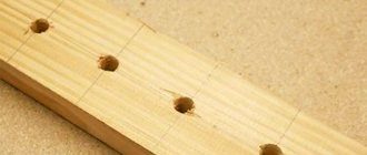
The first test subject will be a piece of fiberboard. The author pierced it with an awl and made several turns with a reamer. Small burrs can be easily cut off with the sharp edge of the tool. The material gives in very easily, and holes are made literally in seconds. In a plastic case, even without a pre-hole, this tool made it very quickly.
And the wooden board also gave up almost immediately. This is the “replacement” for drills, the closest analogue of which is a step drill.
The author pre-drilled an aluminum sheet 2 mm thick, and with a little effort he was able to expand the hole. Thanks to the author for a simple but useful device for the home and workshop!
Good mood, good luck, and interesting ideas to everyone!
The author's video can be found here.
Source
This post may contain affiliate links. This means I earn a small commission from links used at no additional cost to you. See my privacy policy for more information.
reamer, file, do it yourself
Development of a truncated cone
The method described below for constructing the development of a right circular truncated cone is based on the principle of similarity.
Algorithm
- We construct an auxiliary cone ε, similar to the cone ω, as shown in the figure above. For convenience of construction, we choose the diameter d in such a way that the ratio t=D/d is expressed as an integer. In the example under consideration t=2.
- We construct a development of the lateral surface of the cone ε – S0A01020304050A0 and mark the point O0 on the bisector of the angle A0S0A0, choosing its location arbitrarily.
- We draw straight lines O0A0, O010, O020, O030, O040, O050, O0A0 and plot the segments on them [O0A10]=t×|O0A0|, [O0110]= t×|O010|, [O0210]=t×|O020|, [O0310]=t×|O030|, [O0410]=t×|O040|, [O0510]=t×|O050|, [O0A10]=t×|O0A0| respectively, where t=D/d. We connect points A10, 110, 210, 310, 410, 510, A10 with a smooth line.
- From points A10, 110, 210, 310, 410, 510, A10 we draw rays that are parallel to straight lines A0S0, 10S0, 20S0, 30S0, 40S0, 50S0, A0S0, respectively, and on them we lay down segments A10B10, 110120, 210220, 310320, 4 10420 , 510520, A10B10, equal to l – the generator of the truncated cone. We draw the line B10120220320420520B10.
SolidWorks Lessons
Hello, dear users! Sorry that it took me a long time to answer all your questions and suggestions about video tutorials. A lot of work has piled up on projects. Plus, there is no access to high-speed Internet yet. In 1-1.5 months I’ll connect to “normal” Internet and try to devote more time to the site...This short lesson is devoted to constructing a development of a conical hollow part. Nikolai Yemchenko repeatedly addressed this question. I decided to make this answer in the form of a lesson in order to help everyone who had this problem.
So let's get started...
I will demonstrate the implementation of this operation using the example of the part (cone) that Nikolai sent.
We launch SolidWorks and open our part. (For those who don't have it, it was created using the Rotate-Thin-Wall operation).
Please note that the rotation is less than 360 degrees. This is necessary for constructing a sweep - otherwise it will be impossible to do this. If you need high accuracy, then you need to set it to, for example, 359.99999 degrees. In this case, the error will be very small and can be omitted. But often in such cases technological gaps are provided - so this is only to our advantage...
But let's return to constructing the sweep. The Sheet Metal toolbar must be enabled. On this panel, select the button: “Folds”:
Next you need to do two simple steps:
- Select an edge (outer) on the conical face of the cone at the break point.
- Click "OK".
The system will do the rest for you.
Next, to obtain a sweep, you need to extinguish the bent state of the cone:
For ease of use, you can add this state to a new configuration and name it, for example, “Sweep”.
That, in fact, is all “science”. If you have any questions, write on the forum in the “Help me figure it out...” section.
A video was made on this lesson on 11/16/2012:
With uv. Petr Martsenyuk
Similar articles:
Lesson #11. Creating a Wheel Assembly Using Toolbox Library Elements (13627 Hits)
Lesson #14. Creating a 3D inscription in the SolidWorks program. (17579 Hits)
Lesson #13. Creating an array of elements in a SolidWorks part. (11280 Hits)
Lesson #16. Constructing a flat pattern of sheet material in the SolidWorks program (15556 Hits)
Lesson #35. Creating seamless textures for SolidWorks (13014 Hits)
Lesson #46. Construction of a compression spring (two methods). Checking the spring in the Simulation module (CosmosWorks). Create an animation of a compression spring. (20696 Hits)
Lesson #52. Modeling a screw in the SolidWorks environment (two methods). Constructing a scan of a screw turn (21705 Hits)
Lesson #53. Working with the Sheet Metal toolbar. Create a model and flat pattern drawing (22325 Hits)
Lesson #61. Create your own properties using the Property Tab Builder utility (11371 Hits)
Lesson #62. Construction of a 3D stringer (stringer) of a staircase in the SolidWorks program. Reamers of bowstrings and stringers (12790 Hits)
| RSS |
| Sergej — Creating a flat pattern of a conical part | |Your IP address87.110.204.xxx |2010-09-07 02:41:55 |
: joomlacomment
3.26 Copyright (C) 2008 Compojoom.com / Copyright (C) 2007 Alain Georgette / Copyright (C) 2006 Frantisek Hliva. All rights reserved."
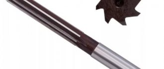
Reamer design
The reamer consists of a cutting surface, a calibrating part, teeth, grooves, clamps, back and front cutting angles. The cone angle varies in the cutting part. For hand tools it is 1-2 degrees, and for machine equipment it reaches 15 degrees. The calibration part consists of a conical and cylindrical section.
The cylindrical base grades the hole in the metal product, and the purpose of the reverse taper is to reduce friction during the calibration process. The rigidity and accuracy of the tool depends on the number of teeth. The more teeth there are, the more accurate and cleaner the hole is. The grooves in the reamer are responsible for control and smooth processing of products. For example, when working with uneven surfaces, a tool with a screw tooth is used - there the grooves are hollowed out in the direction opposite to the rotation - this is necessary so that the reamer does not jam during the drilling process. The rear cutting angle of the product is responsible for the durability of the equipment; it is usually made at an angle of 5-8 degrees. And the rake angle is zero.