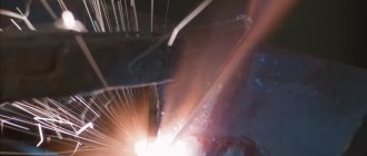
Plasma cutting of metals involves melting the material due to the heat generated by a compressed plasma arc, followed by intensive removal of the melt with a plasma jet.
The areas of application of plasma cutting are very numerous, because this technology is truly universal in terms of the metals cut, the cutting speeds achieved and the range of thicknesses processed.
In addition, the economic efficiency of this metal processing method also deserves attention: plasma cutting is affordable and easy to use, and can be performed not only using machines, but also manually.
Here are the main methods of using automated and manual plasma cutting of metals, widely used in modern enterprises of various industries and sizes.
Plasma cutting of pipes
The most convenient and widespread installations for plasma cutting of pipes are pipe cutters equipped with centralizers. Compared to classic pipe cutting equipment, their advantage lies in the high precision of metal surface processing, which is inaccessible to, say, gas autogenous cutting.
In addition, most plasma tube cutting equipment has useful auxiliary operations, which include surface preparation, seam deburring, chamfering and beveling. For precise movement along the pipe, such equipment is equipped with special drives.
Advantages of artistic cutting on a plasma machine
Plasma artistic cutting has virtually no disadvantages - except that an inexperienced person, setting the wrong mode, can ruin the workpiece. However, when working with CNC-equipped equipment, the likelihood of such an error is extremely low. The advantages of shaped metal processing with a plasma cutter include:
- cutting of any complexity;
- high speed of operations;
- accuracy, cleanliness and evenness of the cut;
- work productivity.
A plasma machine can process all types of metals. If the technology and modes for each of them are followed, burnouts and deformations are excluded.
Plasma cutting of sheet metal
Plasma cutting of metal is mainly used when it is necessary to process thin sheets (here it is almost irreplaceable). In addition, manual plasma cutting of metals in sheets deserves attention, since this technology allows you to create fairly compact devices that are characterized by low weight and energy consumption.
The vast majority of metals can be cut by plasma, including steel, cast iron, bronze, copper, brass, titanium, aluminum and their alloys. The only thing worth considering when working with plasma is the thickness of the sheet of metal being cut, which is determined by its thermal conductivity. The higher the thermal conductivity of the metal, the smaller the thickness of the sheet that can be cut using plasma technology.
KINDS
There are various ways of artistic metal cutting. One of the most popular is plasma cutting. In addition to this, there are the following types:
- Laser cutting;
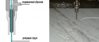
- Waterjet treatment;
- Calibration;
- Mechanical methods;
- Bending;
For each method there is special equipment or hand tools. You can read more about the differences between plasma cutting and laser cutting of metal here.
Figured plasma cutting of metal
Artistic plasma cutting of metal using specialized equipment is widely used in construction and various fields of production. The use of CNC and special programs allows us to produce flat parts of any complexity.
Cutting complex contours with plasma is possible for sheets up to 100 mm thick. Interestingly, the quality of the result does not depend on factors such as the presence of paint, rust, galvanization and contamination on the surface of the sheet. During the process of shaped plasma cutting, the part is locally heated up to 30,000 degrees, and at this temperature any metals melt.
Equipment for artistic cutting
By “smart” equipment, we, of course, mean CNC machines, because only they are capable of:
- perform the operation with millimeter precision;
- guarantee repeatability of the ornament;
- make geometrically complex cuts of sheets and thicker workpieces;
- ensure minimal heating of the workpiece and eliminate the formation of beads on the metal.
On such machines it is possible to engage in both serial and individual production, which metalworking enterprises willingly do.
Plasma cutting of cast iron
Plasma cutting of cast iron is the most reliable and efficient technology today. This method is economical, fast and convenient, and in these parameters it is superior to cutting with an angle grinder and gas. Plasma cutting of cast iron is the most preferable option for heavy industry, for example, if scrap cast iron has accumulated on the territory of the enterprise, which needs to be dismantled and transported. Plasma provides deep cuts in metal, and this makes it indispensable for solving the most labor-intensive tasks in the field of metal cutting.
Let's say a word about pipe cutters
Pipe cutting machines, which can be classified as portal machines, are also very popular. For example, Autom-3 with a plasma cutter is used for cutting pipes. Its speed is several times higher than that of a gas cutter. The most in demand are plasma cutting machines designed for cutting steel pipes with a wall thickness of 38-40 mm. They are able to cut the pipe quickly enough, and its sections will have smooth edges.
If you need to cut pipes with a diameter from 100 to 315 mm made of stainless steel or low-carbon steel (with a thickness of up to 2 mm), which will be used in the installation of industrial ventilation systems, the TV-30 pipe cutter is the most effective. It is capable of operating in manual or automatic mode, having a CNC system. Plasma equipment of this type can be used from a network with a voltage of 380 V, with a compressed air pressure above 0.6 MPa.
A Vanad Miron CNC pipe cutter will achieve high precision. Technological operations for cutting pipes are performed automatically; a temperature of +5 – + 40˚С and exhaust ventilation are required.
A pipe cutting machine is capable of performing some preparatory actions when preparing the surface: cleaning welds, chamfering and cutting edges. It has the ability to cut, in addition to round, square or rectangular pipes.
I use a portable pipe cutting machine when performing work in hard-to-reach places in the case of small-scale orders. For example, Titan PIPR 15-5 plasma machines have a single-phase inverter that performs air plasma cutting; a contact arc ignition method is used here.
Plasma cutting of steel
Plasma cutting can process steel of various thicknesses. Unlike oxyfuel cutting, stainless steel can also be processed by plasma. This technology cuts virtually without a mainsail, which is very valuable for fast and high-quality production.
Plasma cutting of stainless steel has a number of advantages compared to gas cutting:
- High level of security;
- Ability to produce parts of any complexity and shape;
- Minor environmental pollution;
- Fast burning;
- Versatility and cost-effectiveness of technology;
- High cutting speed of small and medium thickness steel;
- Accuracy and high quality of cuts, most often without requiring additional edge processing.
Cutting rolled steel allows you to quickly and accurately produce sheets of a given size, as well as strips - narrow strips of steel with a longitudinal section.
Quality of parts
Comparing the quality of the resulting parts and based on the cost of consumables, we can come to the conclusion that laser cutting is more effective than plasma cutting for thinner sheet materials, and plasma cutting for thicker ones. It should be taken into account that operating costs for both types of cutting vary widely and are largely determined by the geometric parameters of the workpiece, the number of holes in it, and the type and thickness of the material being cut.
| Options | Laser cutting | Plasma cutting |
| Cutting width | The cutting width is constant (0.2 - 0.375 mm) | The cutting width is not constant due to the instability of the plasma arc (0.8 - 1.5 mm) |
| Cutting accuracy | Typically ±0.05 mm (0.2 - 0.375 mm) | Depends on the degree of wear of consumables ±0.1 - ±0.5 mm |
| Taper | Less than 1° | 3° — 10° |
| Minimum openings | In continuous mode, the diameter is approximately equal to the thickness of the material. For pulse mode, the minimum hole diameter can be one third of the material thickness. | The minimum diameter of the holes is 1.5 times the thickness of the material, but not less than 4 mm. Pronounced tendency towards ellipticity (increases with increasing material thickness). |
| Internal corners | High quality corners | Some corner rounding occurs and more material is removed from the bottom of the cut than from the top. |
| Scale | Usually absent | Usually present (small) |
| Burns | Invisible | Present on sharp outer edges of parts |
| Thermal impact | Very little | More than laser cutting |
| Metal cutting performance | Very high speed. For small thicknesses, usually with a noticeable decrease as the thickness increases, prolonged burning of large thicknesses. | Fast burn; very high speed at small and medium thicknesses, usually with a sharp decrease as thickness increases. |
Plasma cutting of concrete
Interestingly, plasma cutting technology can be used to process not only metals, but also concrete, stone and other high-strength materials. However, if plasma arc cutting is used for conductive materials, then materials that do not conduct current (including concrete) are processed using plasma jet cutting technology.
Plasma cutting of concrete is becoming increasingly popular in the field of industrial materials processing. The set of specialized equipment designed for plasma cutting of concrete includes gas cylinders with metering reducers, a mobile transformer, a cutting hose fitting and a grounding electrical cable. With the help of such equipment it is possible to process concrete and reinforced concrete up to 100 mm thick.
However, plasma cutting of concrete also has its disadvantages - the complexity of the work process, the relatively small cutting depth, the bulkiness of plasma installations and the need to use the services of highly qualified personnel.
Cutting with scissors
Metal scissors are quite often used for shaped cutting of metal.
The scissors are capable of cutting metal up to 1 mm thick. The hand tool consists of two cutting knives located at a certain angle of 7-12°.
For shape cutting, curved scissors and finger scissors are used.
Also for shape cutting, guillotine shears are used, which is a machine that is used in industrial conditions.
These scissors have a maximum cutting depth of up to several millimeters thick. The machine can be manual or electric.
Video:
When cutting with guillotines, the cut is smooth, without burrs.
However, not all contours can be cut out using this method; complex shapes are quite difficult to perform.
Each of the shaped metal cutting technologies has certain advantages and disadvantages, which allows you to choose the best option for each case.
Plasma cutting of holes
In modern metalworking enterprises, there is often a need to machine holes for bolted connections. The most advanced plasma cutting machines allow, in real production conditions, to produce holes in metal sheets that are in no way inferior in quality to the results of waterjet or laser cutting.
You can learn more about the technology and plasma cutting machines in this video:
The best option
You can easily order gates made using plasma cutting in Moscow and the region from our company. We provide services not only in the manufacture of this component of the site fencing, but also offer design solutions according to the individual preferences of the customer
Cooperation with us is beneficial:
- Processing orders takes minimal time;
- We work according to individual sketches of clients;
- We produce structures of any complexity;
- We fulfill orders accurately and on time;
- We have a flexible pricing policy and regularly provide substantial discounts.
Our products are of unsurpassed quality and are sure to bring joy and pleasure to all customers.
Typical operator errors during plasma cutting and ways to avoid them
Everyone knows that downtime due to equipment failure causes great losses for production, whereas they could have been avoided with proper use of the equipment.
By paying attention to the things described below in the article and carrying out timely procedures, you can avoid downtime and major breakdowns, save money on repairs, not lose equipment during repairs (or not lose it at all due to non-repairability) and generally increase its service life.
Naturally, special attention should be paid to the wear and tear of consumables, since they wear out over time, and the quality and accuracy of the cut decreases. Increased edge bevel and edge deformation are important indicators to the operator that replacement of an unusable part is required.
To correct these problems, the operator often replaces the entire set of consumables—electrode, nozzle, and protective cap—at once, rather than evaluating each component individually. This results in overuse of consumables, which negatively impacts the overall operating cost and increases production costs.
This article will help you avoid unnecessary expenses and respond to problems in a timely manner, as well as prevent them in advance.
So, here is a list of mistakes to avoid.
Using consumables until they fail
If you look at a number of parts of the same type that were cut out using this approach, you can unmistakably identify those parts for which the nozzle or electrode was already “on the way.” The use of heavily worn nozzles and electrodes can not only lead to defects when cutting the part, but also cause expensive repairs to the flame cutter and even the plasma cutting machine, during which the plasma cutting machine will be idle. Failure of nozzles and electrodes can be easily prevented by several signs indicated by worn consumables. An experienced operator will always tell you when it is time to change the electrode by the sound of cutting and the color of the arc flame (when the zirconium insert burns out, it acquires a greenish tint), as well as the need to reduce the height of the plasma torch when punching. Also, one of the best ways to assess the condition of cutter parts is the quality of the cut. If the quality of the cut suddenly begins to deteriorate, then this is a reason to check the condition of the nozzle and electrode. A reasonable approach is to keep a log of the average electrode or nozzle operating time from replacement to replacement. The nozzle and electrode can withstand different amounts of piercing depending on the cutting current, material type and thickness. For example, when cutting stainless steel, consumables need to be replaced more frequently. Once you have determined from such a log the average lifetime of the electrode for each specific type of cut-out part, you can perform a planned replacement of nozzles and electrodes without leading to defects in the cut-out parts or breakdown of the flame cutter.
| New part | Worn part | |
| Protective cap It should only be replaced if there is visible damage such as slagging, dents or burns, or if it is difficult to fit onto the burner or the protective cap cannot be installed straight due to damage. | ||
| Protective cover Although the safety cap is not worn out by the plasma cutting itself, due to its close proximity to the workpiece, it is susceptible to damage when cutting too close to the material. As its name suggests, the shield cap seals the shielding gas to further cool the nozzles and improve the cutting edge. The hole in the guard is critical to the quality of the cut, so it should be replaced when it becomes burnt, bent, slag, or out of round. An abrasive brush can be used to remove spatter (slag) that is stuck on the protective cover. Always check the O-rings for possible damage such as cracks or tears. Make sure the O-rings are properly lubricated using the manufacturer's recommended lubricant. Refer to manufacturer's manual for lubrication instructions. | ||
| Inner protective ring This part has a copper body with a push-on insulating ring to fit into a protective cover. The purpose of the inner retaining cap is to circulate coolant around the outside of the nozzle and distribute the gas to the containment cap through tiny holes in the insulator ring. This part is not subject to wear by the plasma arc and can easily withstand up to 30 or more electrode changes. Replace only if the hole is burned, bent or damaged and is not round, or if the seal ring or holes around the perimeter are damaged. | ||
| Nozzle The nozzle is one of the most important elements of a plasma torch. The nozzle forms a plasma jet, which, passing through the hole, carries out the cut. When new, this hole will be perfectly round with a well-defined sharp edge. The nozzle should be replaced when the bore begins to wear in the outer or inner bore, making the edges less sharp and reducing the quality of the cut. There may be lighter areas on the inside of the nozzle caused by arcing, but this is not a reason for replacement. For best cutting quality, replace the nozzle twice as often as the electrode. | ||
| Swirl ring (shaz diffuser) The vortex ring is made from a high temperature material such as Vespel or ceramic and is therefore not subject to wear by the plasma arc. It serves to swirl the plasma-forming gas around the electrode and direct it into the nozzle. The vortex ring also isolates the negatively charged electrode from the positively charged nozzle. The diffuser affects many factors, and without it you will get a much shorter life of all other consumable parts and poor cut quality. Care must be taken to keep the small holes free of dirt and debris, and they should be replaced if cracks or chips are found, as even a microscopic crack can disrupt gas flow. Always check the O-rings for possible damage such as cracks or tears. Make sure the O-rings are properly lubricated using the manufacturer's recommended lubricant. Refer to manufacturer's manual for lubrication instructions. On average, 1 diffuser can survive more than 50 electrode replacements. | ||
| Electrode The electrode is the main and consumable material in plasma cutting and requires the most frequent replacement. The electrode may be made of copper or silver or a combination of both and contains a separate emitter rod insert made of hafnium or tungsten. The emitter rod has less current resistance than copper, which prevents the electrode from burning when high arc current is generated. Copper has low electrical resistance, which is why an electric arc can pass through the body, which will cause damage to other elements - the nozzle, the protective cover, as well as the plasma torch itself. To prevent this, the electrode should be changed at the moment when a hole appears on the insert equal in size to the diameter of the insert itself. | ||
| The safe emitter wear depth is approximately 0.040 inch (1.02 mm) for copper electrodes and 0.1 inch (2.54 mm) for silver electrodes. | ||
Replacing nozzles and electrodes too frequently
Among the used nozzles and electrodes, you can often find those that can still be used for cutting. Excessively frequent replacement of consumables is also very common among operators of CNC metal cutting machines, and especially plasma cutting machines. When replacing a nozzle or electrode, the operator must clearly know what to look for. The nozzle requires replacement in the following situations: 1. If the nozzle is deformed on the outside or inside. This often happens when the punching height is too low and the metal is not cut through. Molten metal hits the outer surface of the nozzle or protective cap and deforms it. 2. If the nozzle outlet is shaped differently from a circle. With a high piercing height, if the movement begins before the metal is cut, then the arc deviates from perpendicular to the sheet and passes through the edge of the nozzle hole. To determine whether the electrode is worn out, you need to look at the silver-colored metal insert at the end of the copper electrode (usually an alloy of zirconium, hafnium or tungsten). In general, an electrode is considered operational if this metal exists at all and the depth of the hole in its place does not exceed 2 mm for air plasma or oxygen plasma cutting. For plasma cutting in a protective gas environment (nitrogen or argon), the hole depth can reach 2.2 mm. The swirler needs to be replaced only if a careful inspection reveals clogged holes, cracks, arc marks, or severe wear. Swirl rings are especially often replaced prematurely. The same applies to protective caps, which only need to be replaced in case of physical damage. Very often the protective caps can be cleaned with sandpaper and reused.
Using incorrect plasma settings and consumables
The choice of consumables for plasma cutting depends on the type of metal being cut (steel, copper, brass, stainless steel, etc.), its thickness, the set arc current on the plasma cutting machine, plasma-forming and protective gases, etc. The Plasma Cutting Machine Operator's Reference Guide describes which consumables to use for different cutting process conditions. The modes and recommendations regarding plasma cutting settings specified in the operator's manual should be followed. The use of consumables (nozzles, electrodes) that do not correspond to the current plasma cutting mode usually leads to accelerated failure of the consumables and to a significant deterioration in the quality of the flame cut. It is very important to perform plasma cutting of metal with exactly the arc current for which the consumables used are designed. For example, you should not cut metal with a 100-amp plasma if the plasma cutter has a 40-amp nozzle, etc. The highest cut quality is achieved when the current on the plasma cutting machine is set to 95% of the rated cutting current for which the nozzle is designed. If the plasma cutting mode is set to a low arc current, the cut will be slagged, and there will be a significant amount of burr on the reverse side of the cut parts; the flame cut will be of unsatisfactory quality. If the current set on the plasma cutting machine is too high, the life of the nozzle will be significantly reduced.
Incorrect plasma cutter assembly
The flame cutter must be assembled in such a way that all its parts fit tightly together, and there is no impression of “looseness”. The tight fit of the plasma torch parts ensures good electrical contact and normal circulation of air and coolant through the plasma cutter. When replacing consumables, you should try to disassemble the plasma cutter on a clean surface so that dirt and metal dust generated during plasma cutting do not contaminate the plasma torch. Cleanliness when assembling/disassembling a plasma cutter is very important and yet this requirement is often not met.
Failure to perform regular scheduled maintenance of the plasma torch
A plasma cutter can run for many months, even years, without proper maintenance. However, the gas and coolant passages inside the plasma cutter must be kept clean, and the nozzle and electrode seats must be checked for contamination or damage. Dirt and metal dust must be removed from the plasma cutter. To clean the plasma torch, use a clean cotton cloth and electrical contact cleaner or hydrogen peroxide.
Cutting metal without checking the pressure of the plasma gas or the supply of coolant to the plasma cutter
The flow and pressure of plasma gas and coolant should be checked daily. If the flow rate is insufficient, the torch parts will not be cooled properly and their life will be reduced. Insufficient coolant flow due to a worn pump, clogged filters, or insufficient coolant is a common cause of plasma cutter failures. Constant pressure of the plasma gas is very important for maintaining the cutting arc and for a quality cut. Excessive pressure of the plasma-forming gas is a common cause of difficult ignition of the plasma arc, despite the fact that all other requirements for settings, parameters and the plasma cutting process are fully satisfied. Too high pressure of the plasma-forming gas causes rapid failure of the electrodes. The plasma-forming gas must be cleared of impurities, because its cleanliness has a strong influence on the service life of consumables and the plasma torch as a whole. Compressors supplying air to plasma cutting machines tend to contaminate the air with oils, moisture and fine dust particles.
Punching at a low plasma torch height above the metal
The distance between the workpiece and the plasma torch nozzle cut has a huge impact on both the quality of the cut and the service life of consumables. Even small changes in the height of the plasma cutter above the metal can significantly affect the bevels on the edges of the parts being cut. The height of the plasma cutter above the metal during piercing is especially important. A common mistake is punching when the height of the plasma torch above the metal is insufficient. This causes molten metal to splash out of the piercing hole and onto the nozzles and protective caps, destroying these parts. This significantly degrades the quality of the cut. If piercing occurs when the plasma cutter touches the metal, arc retraction may occur. If the arc is “pulled” into the plasma torch, then the electrode, nozzle, swirler, and sometimes the entire cutter are destroyed. The recommended piercing height is 1.5-2 times the thickness of the metal being cut by the plasma. It should be noted that when punching a sufficiently thick metal, the recommended height is too high, the pilot arc does not reach the surface of the metal sheet, therefore, it is impossible to start the cutting process at the recommended height. However, if the punching is carried out at a height at which the plasma cutter can ignite an arc, then splashes of molten metal may fall on the plasma torch. A solution to this problem may be the use of a technological technique called “jumping”. When processing the command to turn on the cutting, the plasma cutting is turned on at a low height, then the cutter rises up to a given jump height, at which the metal splashes do not reach the cutter. After punching has been completed, the cutter is lowered to the piercing height and begins to move along the contour.
Plasma cutting of metal at too high or too low speed
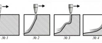
The discrepancy between the plasma cutting speed and the selected mode significantly affects the quality of the cut. If the set cutting speed is too low, the cut parts will have a large amount of flash and various metal deposits along the entire length of the cut on the lower part of the edge of the parts. Slow cutting speeds can cause larger kerf widths and large amounts of metal spatter on the top surface of parts. If the cutting speed is set too high, the arc will bend back, causing distortion of the cut edges, a narrow cut, and small beads of burr and flash at the bottom of the cut edge. The burr formed at high cutting speeds is difficult to remove. With the correct cutting speed, the amount of burr, flash and metal sagging will be minimal. The surface of the flame cut edge at the correct speed should be clean and machining should be minimal. At the beginning and end of the cut, the arc may “deviate” from the perpendicular. This occurs because the arc cannot keep up with the torch. Deflection of the arc leads to the fact that it cuts into the side surface of the nozzle, thereby violating its geometry. If you are cutting from an edge, the center of the nozzle hole must be exactly in line with the edge of the part. This is especially important in combined machines that use both a punching head and a plasma cutter. Arc deflection can also occur when the plasma torch, when cutting is turned on, passes through the edge of the sheet, or if the lead out line intersects the old cut. Fine adjustment of timing parameters is necessary to reduce this effect.
Mechanical damage or breakdown of the plasma cutter
Collisions between the cutter and the sheet metal, cut parts, or edges of the cutting table can completely damage the cutter. Collisions between the cutter and the cut parts can be avoided if the control program specifies idle passes around, rather than over, the cut parts. For example, the ProNest optimal cutting program produced by MTC-Software has such a feature, which allows you to minimize the risk of plasma torch failure and save significant money. Torch height stabilizers also provide some protection against metal collisions. However, if only a torch height sensor based on arc voltage is used, then “pecks” may occur at the end of the cut, because The arc voltage changes as a result of its “deflection” and the cutter moves down to compensate. CNC systems use a multi-level system of protection against collisions with metal. Used as a touch sensor that measures the resistance between the antenna around the torch and the sheet, a capacitive sensor and an arc voltage sensor. This allows you to take full advantage of each sensor type. Also, to protect the cutter, you can use “brittle” brackets, which will break faster in a collision than a plasma cutter. Thus, a competent plasma cutting machine operator can save his business a huge amount of money, time and overhead costs on plasma cutting. The result of the work of a good MTP operator will be increased profitability of plasma cutting and increased profit of the enterprise as a whole. We hope that the recommendations for plasma cutting of metal outlined in this article will allow you to configure plasma cutting and select cutting modes for each specific case.
