Description
A theodolite is a high-precision optical instrument designed to measure angles between selected points “in the field.”
The device is needed in order to survey and measure both horizontal and vertical angles on the topography of the earth’s surface, as well as on industrial and residential structures. It is also designed for measuring rangefinder distances.
Practical and reliable, theodolite is used today in a variety of areas of economic activity. It is used both on land and on water: builders and railway workers, surveyors and geologists, polar explorers and oil workers. With the development of industry and instrument making, the accuracy of measurements is constantly improving and the range of devices is expanding: devices appear on the market that satisfy a wide variety of needs, both in terms of design and functional features, and in price.
In the article we will consider the device of the tool, its principle of operation and application.
Basics of Field Use
A theodolite is not a calculator that you can turn on and intuitively understand its buttons. But working with a theodolite is not difficult if you follow some basic recommendations. The basic sequence of operations consists of the following steps:
- Before starting work, you should read the instructions for your specific device model. Many, even professional craftsmen, for some personal reasons, miss this important step, but it is the operating instructions and other technical documentation of the manufacturer that will allow you to understand the purpose of screws, buttons and keys and find out how to work with a theodolite faster and more clearly attempts at self-study.
In addition to a general description of the device, the instructions for use usually contain a sequence of actions for topographic and geodetic surveys with visual illustrations of measurements. Safety rules and proper storage of the tool will also be useful, allowing you to seriously increase its service life.
- Before starting the actual measurement work, the theodolite is installed in the working position, which consists of sequentially performing the following actions:
- reliable fixation, without any wobble, of the tripod legs on the ground or any hard surface directly affects the accuracy of the resulting readings;
- centering the device over the apex of the angle is achieved by aligning the vertical axis of rotation of the telescope with the apex of the measured angle;
- setting the instrument horizon - the vertical axis of rotation of the theodolite must be brought to a strictly vertical plumb position;
- correct positioning of the telescope comes down to clearly focusing the image of the grid of threads by rotating the ocular knee to the vision of a particular person;
- The installation of a reference system for optical instruments is the precise focusing of images of scales or bar coding of horizontal and vertical circles by rotating the knee of the microscope eyepiece.
Centering of the device and its leveling is carried out by the method of successive approximations.
- Two reference points of the terrain are selected as measurement objects, taking into account the characteristics of the site, or control points of the building structure - A and B. The distance between the selected points should fall in the range of 100 - 400 meters, the specific value of this indicator depends on the scale of the theodolite survey being carried out and the required accuracy of angular measurements.
- The sighting tube is pointed at point A until it is located on the vertical axis of the reticle and readings are taken along the horizontal dial, the measurement results are recorded in a field journal (for optical theodolites) or displayed on a liquid crystal display and stored in the internal memory of the device (for electronic instruments).
Then, when the fixing screw of the tribrach is loosened, the telescope slowly moves smoothly to point B and the corresponding readings are read. If necessary, it is possible to install additional boundary signs.
- Another sub-method, giving together with step 4. greater accuracy of the work performed is to move the telescope to point B through the zenith with a slightly different arrangement of the circle. The permissible deviation of both methods should not be more than twice the accuracy specified for the microscope.
The resulting value of measurements performed in two ways is defined as the arithmetic mean.
- The circular technique often used when it is necessary to measure from one reference point is as follows:
Counting from the next point is carried out by moving the pipe clockwise with the screws slightly loosened. Then the alidade is brought to its original position, the sighting tube is moved through the zenith, i.e. step 5 is fulfilled.
It should be remembered that when calculating the arithmetic mean, it is necessary to take into account the measurement error.
- The measurement of horizontal angles can be carried out without taking into account the position of the device: the telescope is alternately pointed at two reference points, which are the basis for goniometric measurements. At the same time, a countdown is carried out along the limb of the horizontal circle. To determine the base coordinates of object points, the difference in readings should be taken into account.
- The surveyor’s task is not only to obtain the coordinates of reference points, but also to check the results of field measurements, analyze and evaluate their accuracy. For this purpose, certain methods with the necessary calculation formulas have been developed. When electronic models of theodolites are used in geodetic and engineering surveys, calculations are performed automatically with minimal errors, and their results are displayed on a liquid crystal display.
- The theodolite, like any high-precision geodetic instruments, must be subjected to verifications performed by competent metrological authorities or service centers that have a state license to carry out this type of work, and, if necessary, adjustment, once during the calibration interval.
Gradually, theodolites are being replaced by more advanced and, at the same time, more difficult to understand and use devices, the expanded functionality of which invariably affects their significant cost. But, as before, inexpensive theodolites of any type, which perform their functions perfectly, remain favorite and trusted assistants of construction professionals.
By following these simple recommendations on how to use a theodolite, the owner of a geodetic theodolite will give him many years of active work with the most reliable measurements and calculations.
Hello student
Installation of the theodolite in the working position is carried out before starting any work with it, this concerns basic measuring work, or special work related to establishing its operability.
Installing the theodolite in the working position consists of centering it above the vertex of the angle being measured, leveling it, and installing a telescope and reference system for observations. When carrying out verifications, in most cases the theodolite is not centered.
Centering is the alignment of its vertical axis of rotation with the vertex of the horizontal angle being measured. Leveling is bringing the vertical axis of rotation of the theodolite into a vertical position. To center the 2T30P theodolite, a plumb line is used, which is suspended on the hook of the tripod's mounting screw.
Leveling and centering are performed using the method of successive approximations.
Using a screw, the theodolite is attached to the flat head of the tripod through the threaded socket of the stand. The tripod must first be installed so that the plane of its head is approximately horizontal and the tip of the plumb line coincides with the top of the corner.
Rice. 1. Centering the theodolite
In this case, the tripod legs must be securely fixed in the ground, or be stable on a hard surface, such as asphalt. Small movements of the tip of the plumb line above the top of the measured angle are achieved by moving the theodolite itself with a loosened screw. After centering, the set screw must be tightened again.
It is recommended to level the 2T30P theodolite in the sequence indicated below.
1. Set the axis of the cylindrical level in the direction of any two legs of the tripod and, loosening the clamp of the sliding system on one of them, bring the level bubble as accurately as possible to the middle of the ampoule.
Rice. 2. Leveling theodolite a - preliminary leveling with tripod legs; b - leveling with lifting screws of the stand
2. Set the axis of the cylindrical level towards the third leg of the tripod and by changing its length bring the bubble of the level to the middle of the ampoule (item 2). Check position 1 on the two tripod legs.
3. Place the level axis on any two lifting screws of the stand and, by rotating these screws in opposite directions at approximately the same angle, bring the vial exactly to the middle of the ampoule.
4. Set the level axis in the direction of the third lifting screw of the stand (according to the symmetry of the parts of the column or according to the readings on the GK scale) and by rotating this screw bring the level bubble exactly to the middle of the ampoule (position 2). Check position 1, and then again position 2, and, if necessary, correct the position of the bubble.
Installation of a telescope and a reference system for observations consists in establishing a clear (by the eye) image of the reticle by rotating the ocular arm of the telescope and a clear image of the GK and VK scales by rotating the ocular arm of the telescope of the reference system.
Many theodolites are equipped with optical plummets. Installing the theodolite into the working position (centering and leveling) using an optical plummet is performed by approximations.
Find the point in the field of view of the optical plummet over which centering is performed and secure the tripod legs in the ground or on a hard surface, making sure that the image of the point is as close as possible to the center of the field of view of the plummet.
Install the cylindrical level bubble using the tripod legs, and then using the stand lifting screws, as is done when using a plumb bob.
If the centering condition is violated, it is necessary to loosen the set screw and move the theodolite on the tripod head until the center of the field of view of the optical plummet aligns with the vertex of the measured angle. Repeat the centering and leveling steps along the tripod legs and stand lifting screws until the desired result is achieved.
Leveling can be considered satisfactory if, at any position of the theodolite column, the cylindrical level bubble with a horizontal circle deviates from its average position by no more than 2 divisions of the ampoule.
Rice. 3. Optical plummet device
References used: V.N. Popov, S.I. Chekalin. Geodesy: Textbook for universities. - M.: “Mining Book”, 2007.
Download abstract: You do not have access to download files from our server. HOW TO DOWNLOAD HERE
Archive password: privetstudent.com
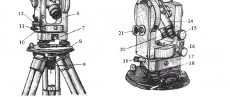
Device
The design of a theodolite consists of basic parts, which became more complex with the development of technology, equipping it with a large number of functions. Tool structure:
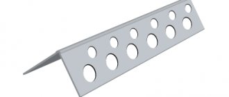
- Metal tripod with adjustable tripod and stand;
- Center plumb line and bubble cylindrical level for level installation of the device on the stand (tribrach);
- Three leveling tribrach lifting screws for leveling the device;
- Alidade – the upper rotating part of the device, on which the movable telescope and reference mechanism are located;
- Alidade screws – guiding and securing;
- Vertical and horizontal (limbo) circles marked by angular degrees;
- Horizontal circle screws: guiding and securing;
- A tube with aiming and fixing screws that adjust image sharpness, an eyepiece on the viewing side and a lens facing the object of observation;
- Eyepiece: lenses with an applied reticle (collimation plane) are installed in it and in the lens; or laser sensor (electronic system);
- Kremalier - a screw element for focusing the image in the eyepiece;
- Supports for the axis of vertical rotation of the tube;
- The reading device is an optical microscope (with a special viewfinder, a scale or line lens and a special mirror or an autonomous light source for reading readings).
Modern models may lack some components (for example, screws or an optical sight of a reading device), but at the same time contain additional elements in the design, for example, a photo-video camera, a laser pointer, a display and a key settings panel.
The main parts of a modern theodolite are the alidade, telescope, dial or horizontal circle, stands, cylindrical level, lifting screws and vertical circle.
Horizontal circle
The horizontal and vertical circles of the theodolite are the main circular axes of the device, necessary for measuring the angular inclination of the object under study.
Horizontal circle, or limb [translated from English. edging] is a ring of glass with dashed angular numerical values (degrees, minutes, sometimes seconds) printed on it.
The scale is a full circle from 0 to 359 degrees.
The dial pitch depends on the accuracy of the theodolite.
Limbo and alidade
Alidade [from Arabic transliteration – alidade – side, side] is the entire upper structural part of the theodolite. It is fixed on an axis directly above the limb and allows the structure to rotate in a horizontal plane.
The alidade includes column-shaped supports: on one of them there is a vertical measuring circle, and in the other there is a microscope of a reading device, with the help of which you can accurately determine the angle specified by turning the alidade along the circumference of the limb. Between the supports there is a tube cylinder movable in a vertical plane. The alidade and the limb are closed with sealed casings made of metal or high-strength plastic to protect them from contamination and deformation.
The alidade, tube and dial are the leading moving elements of the device. The alidade sets the reference relative to the points being studied, after which, to fix the coordinate system, the dial ring is rotated and secured with screws relative to the points being studied.
Any goniometer device, as a rule, consists of the following elements:
- Telescope. Has a certain magnification factor. Attaches to tribrach speakers.
- Vertical and horizontal circle (limbo). They are used to count.
- Scale or line microscope. Needed to take readings from circles.
- A rotating ruler (alidade), rigidly attached to the limbs. There are strokes on it.
- Guide and fixing screws, which are needed for smooth adjustment and fixation of the device’s position.
- Plummet (optical plumb line). Allows you to determine the coordinates of the device above a terrain point.
- Tripod for installing the device.
Theodolite device
The main elements that make up a theodolite:
- Dials with degree and minute divisions (horizontal and vertical).
- Alidade is a movable part of the theodolite, to which the dial and sighting system is attached.
- Telescope (sighting device) with fixing and aiming screws.
- Plumb to center over a point. It can be both optical and laser.
- A tribrach (stand) with lifting screws and a round level for leveling the theodolite.
- Microscope for taking readings.
The complete set of theodolite depends on the area in which it will be used. It can be supplemented with a compass guide, rangefinder attachments, sighting markers, etc. In some works, highly specialized theodolites are used: surveying, astronomical, gyroscopic.
Check and adjustment
Before starting work, most measuring instruments must be calibrated and ensure that it works correctly and that the measured geometric quantities do not exceed the established errors. This procedure is called verification. If, after its completion, it is discovered that the device is not working correctly, it is necessary to perform an adjustment - that is, using screws or keys, correctly set the “zero” readings of the device.
For correct operation of the theodolite, during first operation you should make sure that:
- The main vertical of the device is located parallel to the column-shaped supports and perpendicular to the horizontal measuring circle and alidade;
- The threads in the optical mesh of the tube respectively coincide with the horizontal (determined by horizontal circular rotation with focus on a distant point) and vertical (determined by a remote plumb line on the thread);
- The sighting axes in the tube lenses coincide and form an exact perpendicular to the horizontal axis of the alidade - that is, if the tube is turned 180 degrees, the sighting axis will not shift either to the left or to the right from the base value;
- The axis on which the tube itself is attached has no distortions in height and is perpendicular to the main vertical axis of the theodolite device;
- The horizontal axes on both lenses must be parallel.
In modern devices, the body of which is sealed, the company that manufactured the device is responsible for compliance with these indicators. If discrepancies are observed in any of the verification points, you should contact a specialized workshop or a representative of the manufacturer.
Types of theodolites
Before you pick up a goniometer and start working with it, you need to study the models of theodolites that are presented on the modern market.
Such geodetic instruments are classified according to the following parameters:
- Accuracy. The main parameter that affects the cost of the device is the mean square error in determining angles. There are high-precision, precision and technical theodolites.
- Scope of application (geodetic, astronomical, surveying).
- The design of the reading device (simple, repeatable). Devices with a simple design are equipped with an alidade rigidly attached to a vertical cylindrical axis. In a repeating type device, both simultaneous rotation of the alidade and the dial and autonomous rotation are possible. With this design, repeated measurements of the same angle are possible.
- The physical nature of the information carrier (optical, electronic). The main advantage of the first option is its absolute independence from batteries. In addition, the lack of electronic equipment allows you to work with an optical theodolite under the most unfavorable weather conditions. The operation of electronic devices is based on the binary number system, which allows you to reduce the amount of data and record measurements directly onto the device’s memory card. Thanks to electronic memory, you can forget about multi-page field journals. At the same time, the shooting speed significantly increases and the number of inaccuracies when taking readings decreases.
Principle of operation
The basic principle of operation of the device is to point the telescope at the target, after which, using the geometric projection of the horizontal and vertical axes observed through the lens, it is possible to measure the deflection angles of each axis through a reading device along the dial.
In order to work with a theodolite, the operator requires a certain level of knowledge in the fields of geometry, mechanics and astronomical geodesy, as well as practical skills in handling high-precision devices. Electronic devices existing in industry greatly simplify operation, but it is also advisable to understand the principles of their operation in advance.
In a simplified form, the procedure for working with a theodolite, regardless of its type, comes down to the following steps:
- Placement of a tripod and alignment of the theodolite on a horizontal surface taken as the reference line;
- Alternately pointing at two conventional marks of an object, first “by eye” using a tube, and then more accurately using aiming screws;
- Fixing the values of the location of points with a vertical or horizontal thread on the sight. In this case, you need to move clockwise;
- Carrying out calculations based on data recorded on a horizontal or vertical limb when focusing on each of the points. Thus, the desired value of the angle between the straight lines on which the desired marks are located will be obtained.
Procedure for working with a theodolite
There are two ways to work with a theodolite:
- Polar. The measurements are based on two points with known values. Calculations are made from the second point to the first. Next, measure the distance between them. The final stage is linking the theodolite traverse to each of the marks.
- Using alignments with perpendiculars. This method is used in the production of marking works. It consists of laying right angles on the ground as the device passes each mark step by step.
The instructions for the theodolite clearly state that before you start working with the device, you need to configure it. The preparatory stage includes:
- Centering.
- Leveling.
- Focus.
Instructions for bringing the theodolite into working position
Preparing a theodolite for work includes three main stages: centering, leveling and focusing.
Centering
It involves installing the device with a tripod above the central area of the measuring point. During geodetic operations, a plumb line or an optical plummet is used for centering. The accuracy of the work performed and the accuracy of the center are interrelated. The central point of the geodetic point is determined by eye. The device is placed above this central sector.
The lower area of the deadbolt is equipped with a hook on which to hang a plumb line. Observing the tip of the plumb weight and moving the legs of the tripod, fix the device with an accuracy of 3–5 cm. So that the distance between the tip of the weight and the center does not exceed 3–5 cm. Next, you should press the tripod into the ground, monitoring the position of the device relative to the weight using the weight. center.
The last step should be to loosen the tripod screw. When moving the tribrach with the fingers of your right hand, the tip of the plumb weight should be directly above the center. Having done this, you can tighten the head screw.
Leveling
The ultimate goal of this stage is to ensure that the horizontal circle of the theodolite is in the horizontal plane. The axis of rotation must take a vertical position. The theodolite must be rotated so that the cylindrical level of the rotary ruler is located along the two lifting screws.
By loosening or tightening the lifting screws, the level bubble is brought to the zero point. The bubble can be either on the left side of the middle or on the right. This determines in which direction the lifting screws need to be rotated.
Then the theodolite is turned 90 degrees. Connect the third lifting screw. The bubble leads to the zero point.
Leveling control is carried out by turning the device into several different positions. Leveling is considered successful if, in any arbitrary position, the level bubble deviates from the middle by no more than one notch.
The scheme under consideration is applicable if the alidade of the horizontal circle is equipped with a cylindrical level. Some theodolites have a round level with a rotating ruler. In this situation, the device is fixed in an arbitrary position. They begin to alternately rotate the three lifting screws, bringing the membrane capsule to the zero mark. Carry out quality control of the leveling performed.
Having sequentially centered and leveled the theodolite, you can find that the axis of rotation of the device has assumed a vertical position and passes through the center of the geodetic point.
Focusing
The grid of threads of this geodetic device is focused just before the start of measuring work. Rotate the diopter ring of the eyepiece of the observation tube of the device until a clear picture of the reticle appears.
Focus the scale of the reading mechanism by rotating the diopter ring of the microscope until a clear gradation of the scale is observed. When carrying out focusing and subsequent measurements, try to achieve sufficient illumination of the scale using a backlight mirror.
Before starting measurements, the theodolite is installed in its working position. The maximum accuracy of calculations depends on how securely the device is fixed. Bringing the theodolite into working position consists of installing it above a point: centering, leveling, and also installing a pipe for making observations.
Centering the theodolite serves to align the limb of the horizontal circle with the plumb line that passes through the point where the device is located. Leveling the theodolite brings the axes of rotation into a vertical state. The limb plane occupies a horizontal position at this time.
Primary leveling is done during the installation of the tripod, and fine adjustment is made with screws using a cylindrical level. However, you still need to know how to use a theodolite. To obtain the necessary knowledge for this, naturally, it would be a good idea to take at least an initial training course, since handling such a high-precision device cannot be handled carelessly.
Installing the theodolite in working position and methods for measuring the horizontal angle
When the theodolite is in working position, its vertical axis must pass through the vertex of the angle being measured and occupy a vertical position. To do this, it is necessary to center, bring the vertical axis of the theodolite into a vertical position and install a telescope for sighting by eye.
Centering the theodolite is as follows. First, the theodolite, mounted on a tripod using a mounting screw, is approximately centered over the top of the angle being measured, using a plumb line and burying the corresponding legs of the tripod into the ground. Then precise centering is performed by moving the device along the tripod head. A thread plumb allows you to center the theodolite with an error of about 5 mm. Theodolites of the TZO type can be centered with an accuracy of 1 mm using its telescope, directed with the lens down.
Installation of the theodolite (leveling) , i.e., bringing the plane of the horizontal limb to horizontal, and the vertical axis of the device to a vertical position, is carried out using lifting screws and a cylindrical level mounted on the alidade of a horizontal circle. To do this, place a cylindrical level in the direction of the two lifting screws of the stand and, rotating them in opposite directions, install the bubble at the zero point. Then the alidade is rotated 90° and, using the third lifting screw, the bubble is again brought to the zero point. In a correctly installed theodolite, the cylindrical level bubble should not deviate from the zero point by more than one division of the ampoule at any position of the alidade on the limb.
Installing a telescope for sighting by eye
consists in obtaining a clear image of the mesh of threads and the observed object. To obtain a sharp image of the reticle, point the telescope at the sky or a white illuminated object and rotate the diopter ring of the eyepiece. The clarity of the image of the observed object is achieved by moving the focusing lens of the telescope, for which purpose the ratchet ring is rotated. The telescope is usually installed once over the eye and focusing is adjusted only if necessary. Installation on an object is carried out each time when pointing at sighting targets at different distances.
The clarity of the image of the divisions of the limb and the reading scale in the microscope is achieved by rotating the diopter ring of the microscope.
Measuring horizontal angles. To reduce the influence of the eccentricity of the alidade of the horizontal circle, and when measuring angles between sighting targets located at different angles of inclination relative to the horizon, and, accordingly, to eliminate the influence of collimation error and the inclination of the horizontal axis on the final result, the angle is measured at two positions of the vertical circle: left ( L) and right (P). full angle measurement
.
A single measurement of an angle at one (any) position of a vertical circle is called half-
.
Horizontal angles between points and points in the geodetic network can be right
or
left
along the way. The sequence of pointing the telescope at the rear or front points depends on what angle (right or left) needs to be measured. In this case, one should take into account the direction of increase in the signatures of the dial divisions (clockwise or counterclockwise). In theodolites of the TZO type, the divisions of the limb are signed in a clockwise direction.
Measuring an angle using a method. The theodolite is installed above point 3 with the vertex of angle β
(Fig. 5.36,
a
), bring it into working position, secure the limb and, having released the alidade, sequentially sight with a telescope at the milestones placed at points 2 (back or right) and 4 (front or left), lying on the sides of the horizontal angle .
If point 2 is considered posterior and point 4 anterior, then angle β
will be right along the way. To accurately point the center (cross) of the telescope reticle at the target, use the alidade screws of the horizontal circle and the telescope, and after pointing at each point (2 and 4), take readings on the microscope scales.
Let us denote the readings when sighting at the rear point 2 as a1
, and to the front point 4 - through
a2
.
In the first case, they correspond to the arc aa1
, in the second -
aa2
(Fig. 5.36,
a
). Then the desired angle between the two directions is equal to the reading to the back point minus the reading to the front point:
β = a1 - a2.
Rice. 5.36. Scheme for measuring horizontal angles:
A)
- method of techniques;
b)
- by repetition
These actions with a theodolite constitute the first half-step of measuring an angle.
Having finished measuring the angle with the first half-step, the telescope is moved through the zenith, the horizontal dial is unfastened, turned clockwise by approximately 1-2° and secured again. After this, they begin to measure the angle β
at the second position of the vertical circle (at L, if in the first half-move it was measured at P), performing all the actions as in the first half-move.
This is the second half-technique
for measuring the horizontal angle
β
. All readings are recorded and the measured angle is calculated in a journal (Table 5.1).
Two half steps make up a full angle measurement technique. The final value of the measured angle is taken as the average value of the angle from two half-measures in case of an acceptable discrepancy between them. For our example, the final angle value is 87°11.2′, which is the result of a full angle measurement.
The admissibility of discrepancies in measurement results between the first and second half-measures, as a rule, is determined by the accuracy of the theodolite and technical requirements and should not exceed double the accuracy of the reading device.
If the discrepancy is unacceptable, then check the entries and calculations in the journal and, if there are no errors in the calculations, the angles are measured again, carefully crossing out the erroneous results with one line.
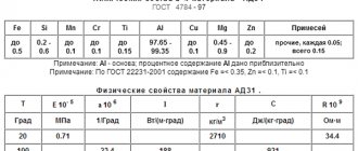
Table 5.1
Journal of horizontal angle measurements
Date 05/13/1995 Theodolite: 2T30 No. 40687 Observed by: Beglyarov N.S.
Weather: cloudy Visibility: good Recorded by: Knopin K.N.
Note. The numbers in parentheses indicate the sequence of actions when measuring the angle and recording the results in the journal.
If the reading to the back point is less than the reading to the front point in absolute value, as shown in table. 5.1 for half-reception at P, then when calculating the angle according to formula (5.31), 360° is added to the reading for the back point and the reading for the front point is subtracted from the resulting amount. In our example β
=19º 01.5′ + 360º - 291º 50.5′ = 87º 11.0′.
Each reading is recorded in the field journal for measuring the horizontal angle in clear numbers. In the journal, it is strictly forbidden to erase an entry, carelessly cross out, covering up the previous value, or write a number by number. All calculations are performed directly at the station and only after making sure of the quality of the measurements do they move on to the next point.
Measuring angles using circular techniques. If at a given point it is necessary to measure horizontal angles between several directions, use the method of circular techniques. To do this, the theodolite is brought into working position above the vertex of the angle being measured, the dial is secured and, rotating the alidade clockwise, sequentially sighting at all points in the given directions. Readings are taken along the horizontal limb. The last sighting is made again to the starting point. The resulting reading along the horizontal limb should not differ from the one taken during the initial sighting at the same point by an amount exceeding 2t - the double accuracy of the reading device. Such actions with a theodolite constitute the first half-technique
.
After this, the theodolite's telescope is moved through the zenith and again sequentially sighted at the same points, but in the reverse order, i.e., rotating the alidade counterclockwise. Finish the measurement by sighting and counting to the starting point. These actions constitute the second half-move.
Two half-steps make up one measurement step. Several such techniques are used to increase the accuracy of measurements and weaken the influence of dial division errors, but before each of them the dial is rearranged to an angle of 180°/n, where n is the number of techniques.
Measuring an angle by repetition. The repetition method is used to increase the accuracy of angle measurement by slightly reducing the measurement errors in it. The essence of the method is that, at the same position of the vertical circle, the horizontal dial is rotated n times successively by the value of the measured angle β
, as if repeatedly plotting this angle on the limb to the value “n
β
” (Fig. 5.37,
b
).
After bringing the device into working position above the apex of angle β, set a reading on the limb close to 0º or equal to 0º 00′ and fix the alidade on the limb. Then, having released the dial fixing screw, rotate it together with the alidade and accurately sight the left point C and secure the dial. They take a reading from the microscope and write it down in a journal. Then they unfasten the alidade of the horizontal circle and, smoothly rotating it clockwise, sight at the right point A, performing the final alignment of the cross of the grid of threads with the sighting target by screwing in the alidade aiming screw. A control reading is taken from the microscope (in Fig. 5.37, b
it is equal to 87º13′).
The described actions constitute the first
repetition.
Then proceed to the second repetition of the angle measurement. To do this, leaving the dial and alidade fastened, release the dial fixing screw and smoothly rotate the alidade with the dial clockwise until the sighting axis is projected onto point C. After this, the dial is fixed without making a reading, the alidade is released and sighted with a telescope at the point And, finishing the final aiming at it by rotating the alidade aiming screw. Microscope readings are not made. This completes the second repetition. Subsequent repetitions are performed in the same order, ending with n
- repeated repetition (measurement) of the angle by sighting at the right point A, after which the last reading is taken from the microscope.
Measuring an angle by combining the zeros of the limb and alidade. Using the “from zero” method, angles are measured with a repeating theodolite in one half-step for quick control of the measured angles. This method consists of standing at point 3 (see Fig. 5.36, a
), by turning the alidade, set it to a dial reading equal to zero.
Then, by turning the dial with the alidade, point the pipe (sighting axis) along the left side of the corner to point 4 and secure the dial. Now, having released the fixing screw and rotating the alidade, point the pipe along the right side of the angle to point 2 and, taking a reading along the limb in the microscope, obtain the value of the measured angle β
.
Note. 1.Angle β
will be polar if direction 3 - 4 is taken as the polar axis. When topographically surveying an area, this technique is called the polar survey method.
2. Construction of the given (design) angle β
from the original direction is carried out as follows.
After fastening the limb and alidade at the zero reference and orienting the limb along the original left side of the angle, the alidade is unfastened and rotated clockwise and set to a reference along the limb equal to the value of the given (design) angle β
. In the direction of the telescope (sighting axis), the design point is secured with a peg - the end of the design line.
Measurement of magnetic azimuths of lines. To orient terrain lines along the magnetic meridian, along with measuring the angle, you can measure the magnetic azimuths of the sides of the angle using a reference point - a compass. To do this, after fastening the limb to the alidade at the zero reference point, rotate it to the zero reference point along the reference compass ring against the northern end of the magnetic needle. Then the zero diameter of the limb will be oriented along the magnetic meridian. The limb is secured. Now, by detaching the alidade and pointing the telescope at the point being photographed, the value of the measured magnetic azimuth is obtained by reading along the limb.
Preparing for work
In order to carry out high-quality measurements on the ground, it is important to install the theodolite and bring it into working position.
To do this, a series of preliminary operations are carried out sequentially.
Centering
This is the first stage of deployment of the device, which involves choosing a central reference point when taking measurements. When the point is determined, the operator strengthens the tripod over it, and then, using optics (plumb line) or a thread with a weight attached to the tripod (plumb line), levels the platform so that it is located along the center line and parallel to the plumb line. Thus, a theodolite placed on a tripod will not deviate along the vertical axis.
Leveling
After the device is level vertically, it is also necessary to align it along the horizontal axis. This procedure is called leveling and is carried out by three lifting screws of the horizontal alidade. Depending on the model of the device, you need to focus on the cylindrical or round level of the alidade of the horizontal circle. Operating the screws, the operator brings the air bubble of the level to position 0. The permissible deviation should not exceed 1 division at the level.
Focusing
After the theodolite is aligned and fixed in the center of the reference point, focusing is carried out - adjusting the accuracy of drawing the grid of the telescope and the reference device. The first is carried out by turning the eyepiece ring of the tube until the reticle threads are visible as clearly as possible.
To focus, the second operator should rotate the diopter ring on the reading device, achieving a clear vision of the division lines on the microscope scale.
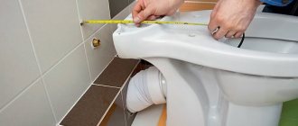
During construction, it is very important to lay the foundation correctly. The further construction of the building will depend on this. At the initial stage, measurements are taken using various professional instruments: levels, range finders, tacheometers. Theodolite replaces them all. With its help, you can measure angles and distances (if a rangefinder is built-in) between walls, partitions, and structural elements.
Expert advice. It is recommended to install reinforced concrete piles on clayey, swampy soil. They are also used in the construction of houses in close proximity to other buildings. The piles must be in a vertical position. If the deviation is more than 1.5 - 2°, equalization measures must be taken. If the piles are tilted, the entire building may skew and collapse over time.
Before going to the site, you must check the serviceability of all the elements of the theodolite: the telescope (is it well secured and rotates), screws, control unit, level ampoules, the integrity of the optical lenses and surfaces, as well as the presence of all parts included (brushes) , plumb bob, raincoat, tribrach, tripod and others).
Preparation is the first and most important step in measurements. Everything further will depend on him. If the theodolite is installed incorrectly, the results will be unsuccessful.
At the construction site, you need to find a flat surface into which we firmly insert the tripod. The distance from the subject of measurement should not exceed the minimum viewing distance specified in the device passport. Typically this figure is from 1 to 2 meters. Adjust the height of the legs to suit your height. Remember that the tripod must be strictly vertical.
To secure the theodolite, you need to install a tribrach (stand), and then the device itself on it. Use a cylindrical level to ensure all settings are level. The bubble should be in the middle of the flask. Correctness can also be checked by using the plumb line provided in the kit and the sight over the telescope. The cross in the viewfinder lens must be aimed exactly at the object.
The next step is to set up and secure the telescope. To ensure that the image of the object in the eyepiece is clear, smoothly turn the wheel on the tube. If the equipment is equipped with not only a direct, but also an inverted image, rotate the spotting scope 180 degrees and see if the sight matches the object.
The 60 scale divisions (each usually corresponding to 1 arc minute) should be clearly visible. The letters H and V near the scales correspond to the horizontal and vertical circles, which also need to be adjusted. The stable position of all elements is ensured by screws. Before measuring, you must also remember about locking the compensator, which is done using a special button or screw.
Measuring the angle with an optical theodolite when installing the foundation is carried out as follows. In places where walls are supposed to be erected, there should be a temporary frame made of boards. Using an optical theodolite, we point the eyepiece at a certain point on one of the temporary walls, and take it as zero. Then we aim the lens at a point on the wall that is at an angle relative to it.
From the coordinates for the right direction, subtract the data for the left direction. If the values for the right direction are less, you need to add 360 degrees to them. We also measure all corners of the building. Horizontal angles must be straight. The vertical angle is measured using a similar system, but we subtract the coordinates of the upper direction from the coordinates of the lower direction.
When using a digital device, measurements are much easier and faster. Let's consider this process using the example of the theodolite model CST/berger DGT10 F0340543N0. We set the target - this point will be considered zero; to do this, press the “OSET” button. Next, we “translate” the telescope to another object and fix it.
Numbers will appear on the screen, which will be the coordinates of this horizontal angle. We remember the readings by pressing the “HOLD” button. To measure the vertical angle, we direct the telescope to the desired point and fix the position with screws on both sides. After this, you can take measurements using the technology presented above.
Correct operation
Regardless of which model of theodolite – electronic or classical – you are going to use, it is important to remember that this is a sensitive, high-precision device that requires careful handling and correct operation.
It should be transported from point to point in a special box or case designed for a specific model, trying to prevent the device from shaking or falling from a height.
Mechanical parts of the structure must move freely when rotating on axes or screws, but should not be loose and, if necessary, tightly fixed during operation of the device.
It is also recommended to always carefully monitor the optical components - eyepieces and sights must be protected from dust and dirt, and not allowed to deform (chips, cracks, etc.)
Special attention is paid to the tripod - when placing it, you should make sure that the tripod is positioned stable and that all legs and the platform are firmly fixed.
To perform high-precision measurements, it is important to know all the subtleties when handling a geodetic instrument. It largely depends on the skills of the surveyor to what extent the figures obtained during the measurement will correspond to the real state of affairs, and whether the structure being built will be sufficiently strong and durable.
This geodetic device has a number of advantages:
- With its help, you can carry out the most accurate angular measurements, regardless of extreme climatic conditions and specific terrain. It operates without interference in the temperature range from -25 to 50 degrees.
- The accuracy of the data obtained is not affected by non-standard working conditions, so the theodolite can be taken even on expeditions.
- The compact size makes the device easy to transport.
- Elementary and fast calibration and adjustment.
Advantages of theodolite
A goniometric apparatus such as a theodolite has a number of advantages:
- High accuracy of measurements.
- Ability to take measurements in different climatic conditions.
- The device can be used in areas with any terrain.
- Compact and mobile.
- Relative ease of calibration and adjustment.
Measuring vertical angles with a theodolite - how to do it yourself?
First, the device must be sufficiently securely mounted on a tripod. Next, two points of the object to be measured are selected. Using a screw and a diopter ring, the telescope is aimed at the selected points.
After this, the vertical thread of the telescope is aligned with one of the points and data is read from the horizontal circle. Gradually loosening the fixing screw, the pipe is moved clockwise to another point and readings are also taken.
Measuring angles with a theodolite is sometimes done using a circular technique, which is advisable when measurements have to be taken from one point. To do this, the theodolite is installed in the right place. The limb should be as close to zero as possible.
Then they begin to rotate the alidade until the zero line of the microscope is completely aligned with the zero line on the limb. Next, you should loosen the clamp a little and direct the pipe to the point. At the end of the measurements, tighten the locking screw and make calculations.
The measurement of horizontal angles with a theodolite is carried out regardless of its position. To carry out such measurements, the telescope is alternately pointed at a pair of points between which it is necessary to take measurements, and at the same time a reading is taken along a horizontal circle. The angle is determined based on the difference in readings.
Measuring horizontal angles using a theodolite takes place in two or three stages, depending on the type of device. If a classic theodolite is used, one computational one will be added to the two measuring ones.
Assuming that the vertex of the desired angle is the installed device, the operator points the vertical thread of the telescope reticle at the first mark and fixes the value on the horizontal limb. In modern theodolites with electronic “stuffing”, the mark is determined on the dial automatically and fixed as 0 using buttons on the instrument panel; in traditional ones, it is noted by the operator through the eyepiece of the reading device and entered into the measurement log.
After this, the tube is aimed clockwise at the second mark. The electronic device will calculate the angle itself and display the readings on the screen. When working with a traditional device, the operator will have to take readings from the horizontal limb through a microscope and, through geometric operations, calculate the value of the desired angle.
Step-by-step instructions on how to use a theodolite
- 1 step. When working with geodetic equipment, it is worth considering that in order to obtain accurate measurement results, it is necessary to carry out regular checks and adjustments of the theodolite. In addition, it is necessary to periodically monitor the geometric parameters, since the results of the work of a surveyor or builder sometimes do not tolerate errors even of a few arc seconds.
- Step 2. Once the equipment has been checked, you can begin working with the theodolite. First, you need to fix the device above a point with known coordinates, using a tripod and a plumb line or a plumb line. Taking it as a reference point, use levels and guide screws to center the device. The result should be an absolutely horizontal position of the device, as well as the location of the theodolite strictly above the point.
- Step 3. Using the sighting device, you must first aim at the target, and use the screws to align the reticle with the target as accurately as possible. This way the center of the measured object is determined. These actions are performed using a spotting scope, but if there is insufficient light, you can additionally use a special backlit mirror. After completing this procedure, measurements of the vertical and horizontal angles are taken using a theodolite microscope.
- Step 4 To obtain high reliability of measurement results, it is recommended to repeat measurements with a theodolite several times (techniques). Based on the results of repeated measurements, the average values of vertical and horizontal angles are determined.
Algorithm for working with the device
- Using a tripod, install the theodolite.
- The observation tube is directed towards two reference points.
- Pointing the device at the first point, fix and measure the vertical thread.
- Count down in a horizontal circle. The obtained data is recorded on paper. A similar operation is carried out with another point.
- The observation tube is moved past the zenith, and then the position of the circle is changed.
- In case of minor discrepancies, stop at the average value.
- The dial reading should be zero or tend to this value.
- The alidade is rotated until the zero marks on the dial and the microscope coincide.
- Carry out the next round of measurements.
In order for the device to constantly show the correct values, you should take care of its storage conditions. It is best to store the theodolite in a special case. Place and remove the device, holding it by the stands or handles. Having completed work with the device, before storing it in the case, loosen the screws located on the telescope and alidade.
When installing a tripod, loosen the screws. After making the adjustment, the screws are fully tightened. The mounting screw is used to securely fix the theodolite immediately after it is installed on the tripod. The guiding and lifting screws do not relax or tighten all the way. When moving the theodolite over short distances, it is thrown onto the shoulders along with the tripod. The device must travel long distances when placed in a case.
What is a level
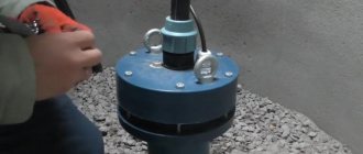
In cartographic and geodetic measurements, another device is used in conjunction with a theodolite - a level.
The device is used to determine the horizontal surface and measure the difference in heights on a landscape or a building under construction.
The main difference is that the level is simpler in design than a theodolite, but an assistant is needed to work with it when performing calculations. In the basic configuration, the device also consists of a tube mounted on a tripod, but, unlike a theodolite, the level has only one horizontal plane of rotation.
It is along it that the operator orients the mesh of the instrument tube while taking measurements. In this case, the difference in heights is recorded using a marked rod, which is held vertically by an assistant at the measurement point.